

Page 1
INSTALLATION AND MAINTENANCE INSTRUCTIONS
3825 Ohio Avenue, St. Charles, Illinois 60174
1-800-SENSOR2, FAX: 630-377-6495
SSK451 Multi-Signaling Accessory
Specifications
Dimensions: 4.8˝ W x 4.7˝ H x 1.5˝ D (12.2 cm W x 11.9 cm H x 3.8 cm D)
Weight: 0.35 lb. (160 g)
Operating Voltage: 24 VDC
Power Requirements
Standby: 8 mA
Trouble: 16 mA
Alarm w/o strobe: 40 mA
Alarm with strobe: 65 mA
Connections: Strip terminal, 14 AWG to 22 AWG wire
Sounder: 87 dBA at ten feet
Temperature: 14°F to 140°F (-10°C to 60°C)
Humidity: 95% relative humidity; non-condensing
Listing: UL 268A
I56-1222-004
www.systemsensor.com
Notice: This manual should be left with the owner/user of
this equipment.
General Information
The National Fire Protection Association (NFPA) has published codes, standards, and recommended practices for the
installation and use of this product. It is recommended that
the installer be familiar with these requirements, with local
codes, and any special requirements of the local authority
having jurisdiction. For further information, consult NFPA
72 and 90A requirements.
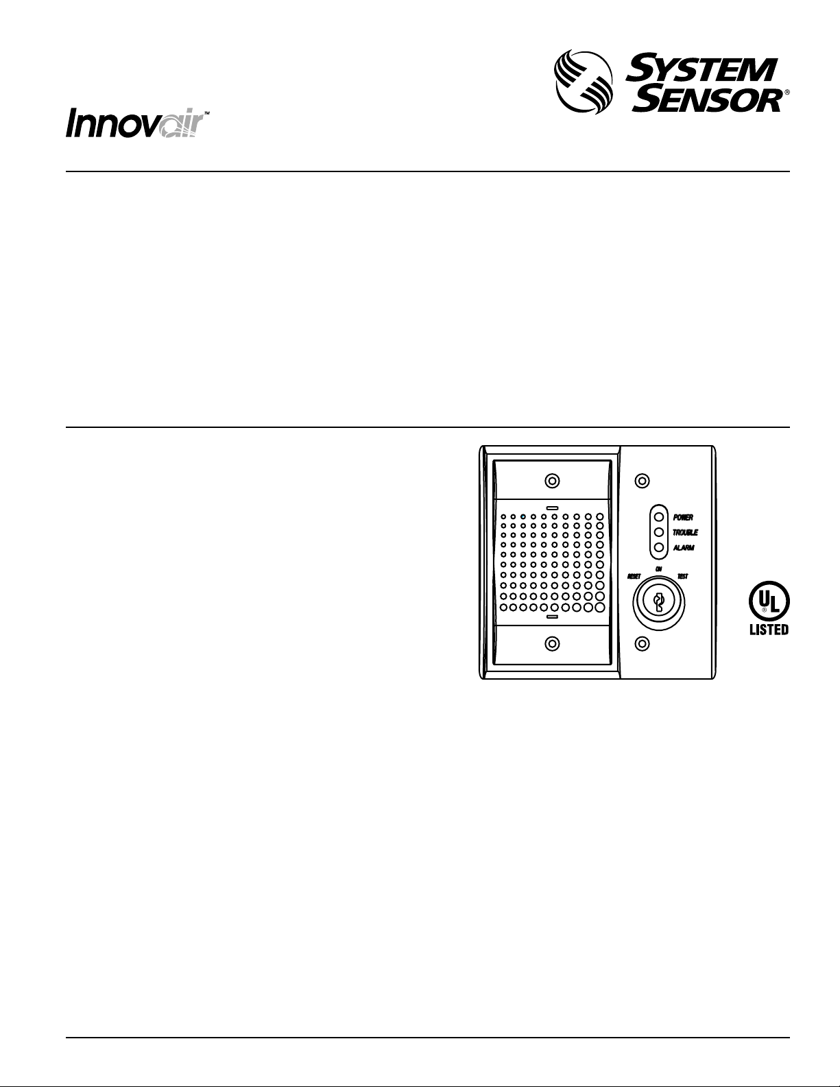
The System Sensor SSK451 multi-signaling accessory is
designed for use with System Sensor DH100ACDC and
DH400ACDC duct smoke detector models and combines a
horn feature with the key-activated test and reset functions.
Green, yellow and red LEDs provide a visual indication of
power, trouble and alarm conditions, respectively.
To meet special code requirements of certain jurisdictions,
an optional PS24LO strobe can be easily added to the
SSK451 to provide visual alarm signaling. A “SMOKE” lens
can be added to the strobe.
The SSK451 can be wired such that its horn produces either
a continuous or a temporal tone. The SSK451 conveniently
installs to a double-gang electrical box.
Contents
1 SSK451 Multi-Signaling Accessory
1 Mounting Hardware Kit (contains 4 mounting screws,
and 2 spacers for optional PS24LO strobe)
1 Installation and Maintenance Instructions
H0482-00
Installation
Wire the SSK451 as shown in Figure 1, for DH100ACDC
duct smoke detectors, or Figure 2, for DH400ACDC duct
smoke detectors. Limit wire runs to 25 ohms or less per
interconnecting wire.
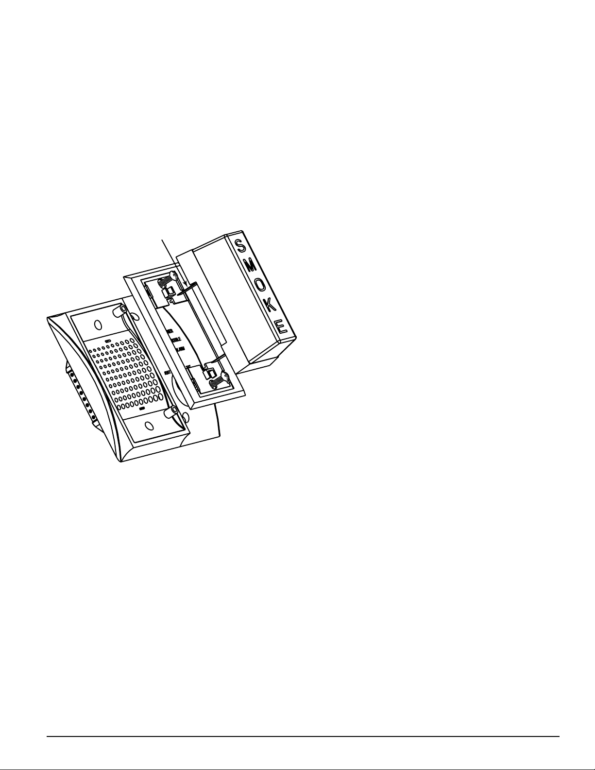
Test Coil Installation
NOTE: When the SSK451 is used with a DH400ACDC duct
smoke detector, a test coil, part number COIL400, must
be ordered separately. When the SSK451 is used with a
DH100ACDC duct smoke detector, a test coil is not required.
The COIL400 is installed in the DH400ACDC duct smoke
detector housing as shown in Figure 3. Please follow the in-
structions enclosed with the COIL400 for proper installation
of the COIL400 to the DH400ACDC duct smoke detector.
D200-94-00 1 I56-1222-004
Page 2
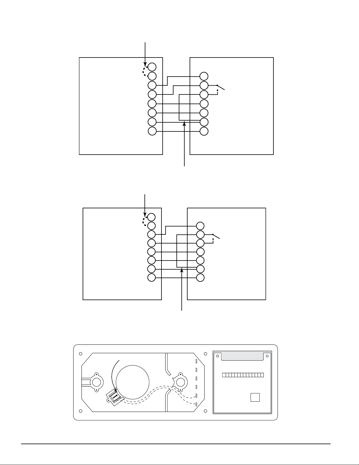
Figure 1. SSK451 with DH100ACDC Duct Smoke Detector:
COMMON 3
TEMPORAL SELECT 2
ALARM SIGNAL 1
SUPERVISORY SIGNAL 4
RESET 7
TEST 8
POWER (-) 6
POWER (+) 5
SSK451
FIELD INSTALLED
JUMPER FOR
TEMPORAL PATTERN
15 ALARM SIGNAL
3
SUPERVISORY
14
CONTACT
2 RESET
11 TEST
20 AUX. POWER (-)
19 AUX. POWER (+)
DH100 ACDC
NO
FIELD INSTALLED
JUMPER
COMMON 3
TEMPORAL SELECT 2
ALARM SIGNAL 1
SUPERVISORY SIGNAL 4
RESET 7
TEST 8
POWER (-) 6
POWER (+) 5
SSK451
FIELD INSTALLED
JUMPER FOR
TEMPORAL PATTERN
5 ALARM SIGNAL
10
SUPERVISORY
11
CONTACT
3 RESET
4 TEST
6 AUX. POWER (-)
7 AUX. POWER (+)
DH400 ACDC
NO
FIELD INSTALLED
JUMPER
DETECTOR
HEAD
TEST COIL
Figure 2. SSK451 with DH400ACDC Duct Smoke Detector:
NOTE: Wiring
diagram shown is for
DH100ACDC 4-wire
duct smoke detector
system equipped
without a control panel.
H0483-00
Figure 3. Test Coil Installation:
NOTE: Wiring
diagram shown is for
DH400ACDC 4-wire
duct smoke detector
system equipped
without a control panel.
H0484-00
H0277-00
D200-94-00 2 I56-1222-004
Page 3
Temporal Sounder
RED TERMINAL
ON TOP
The SSK451 accessory provides the option of sounding a
continuous or temporal pattern. The SSK451 will default to
sound in a continuous pattern. For a temporal pattern, wire
a field-installed jumper between terminals 2 and 3 on the
SSK451.
Mounting
Secure the SSK451 to a double-gang electrical box with the
four mounting screws provided.
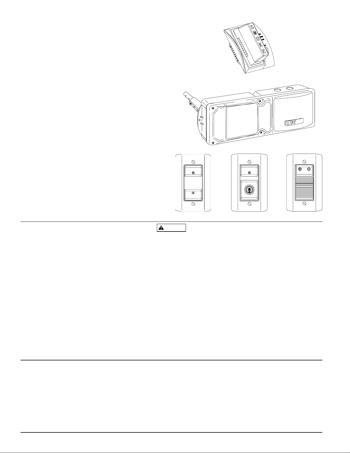
Installation of the Optional Add-On PS24LO Strobe
This optional strobe can be purchased separately and is
easily added to the SSK451 accessory.
Figure 4:
H0485-00
The PS24LO strobe will be mounted on top of the sounder,
on the left-hand side of the SSK451. Place one mounting
spacer between the SSK451 and the strobe adapter plate at
each screw attachment location. Attach the adapter plate,
spacer and SSK451 to the left-hand side of the double-gang
electrical outlet box with two mounting screws.
Slide the strobe terminals directly into the two slots in the
adapter plate and SSK451. The positive lug, which will be
colored red, must be installed into the top slot.
Grasp the catch area on the top of the strobe and squeeze
while applying inward force. Repeat for the catch area on
the bottom of the strobe.
Make sure the strobe catches fully engage into the slots in
the adapter plate and that no gap appears at the interface
between the strobe and adapter plate.
Optional SMOKE Strobe Lens
NOTE: To meet the code requirements of certain jurisdictions,
an optional SMOKE lens can be purchased separately.
SMOKE lens, wall mount PS12/24SLENSW
SMOKE lens, ceiling mount PS12/24SLENSC
Please follow the instructions enclosed with the lens for
proper installation of the lens to the strobe.
Operation
The green “POWER” LED is illuminated whenever the duct
smoke detector is receiving power. With a DH100ACDC duct
smoke detector, the yellow “TROUBLE” LED is lit when the
sensor board is missing or the cover is removed for more
than twenty minutes. With a DH400 ACDC duct smoke de
tector, the yellow “TROUBLE” LED is lit when the detector
head is missing. The red “ALARM” LED is displayed and
the horn will sound whenever the duct smoke detector is
in alarm.
No LEDs will be illuminated if the duct smoke detector is
not receiving power.
Test Function
Insert the key and turn clockwise to the “TEST” position.
The red LED will illuminate and the horn will sound. If an
optional strobe is installed, it will pulse.
Alarm Indication
With the key in the “TEST” position, some time will elapse
(40 seconds maximum), depending on the duct smoke de
tector type, before the red alarm LED will illuminate and
the horn will sound.
Reset Function
Turn the key counterclockwise to the “RESET” position and
hold. The red alarm LED should turn off and the horn will
cease sounding. Then, turn the key back to the “ON” position and remove.
-
-
D200-94-00 3 I56-1222-004
Page 4
WARNING
ON
RESET TEST
ALARM
ALARM POWER
ALARM
RESET
T
E
S
T
Ordering Information
SSK451 Multi-Signaling Accessory
PA400B Mini-Alert™ Sounder, beige
PA400W Mini-Alert™ Sounder, white
PS24LOB Mini-Alert™ Add-On Strobe, beige
PS24LOW Mini-Alert™ Add-On Strobe, white
PS12/24SLENSW Smoke Lens Wall Mount
Innovair Duct Smoke Detectors
DH100ACDCP 4-Wire Photoelectric Duct Smoke Detector
DH100ACDCI 4-Wire Ionization Duct Smoke Detector
Other Accessories
RTS451 Remote Test/Reset Station
RTS451KEY Key-Activated Remote Test/Reset Station
APA451 Piezo Annunciator
RA400Z Remote Annunciator Alarm
H0490-00
H0488-00
H0489-00
H0486-00
The sounder or sounder/strobe combination will not operate if
the power is cut off for any reason.
If power is cut off for any reason, the sounder or strobe/sounder
combination will not provide the desired audible or visual warning.
The sounder may not be heard. The loudness of the sounder
meets or exceeds the current Underwriters Laboratories’ stan
dards. However, the sounder may not alert a sound sleeper or one
who has recently used drugs or has been drinking alcoholic bever
ages. This sounder may not be heard if it is placed in an area that
is separated by a closed door, or if it is located on a different floor
from the person in a hazardous situation, or if it is placed too far
to be heard over ambient noise, such as, traffic, air conditioners,
machinery or musical appliances that may prevent alert persons
from hearing the alarm. For these reasons, Pittway recommends
that sounders (85dBA minimum at 10 feet) used in a residence
shall be placed on every level and in every bedroom that does not
have a smoke detector with a built-in sounder.)
Three-Year Limited Warranty
System Sensor warrants its enclosed product to be free from defects in
materials and workmanship under normal use and service for a period
of three years from date of manufacture. System Sensor makes no other
express warranty for the enclosed product. No agent, representative,
dealer, or employee of the Company has the authority to increase or alter
the obligations or limitations of this Warranty. The Company’s obliga
tion of this Warranty shall be limited to the replacement of any part of
the product which is found to be defective in materials or workmanship under normal use and service during the three year period commencing with the date of manufacture. After phoning System Sensor’s
toll free number 800-SENSOR2 (736-7672) for a Return Authorization
number, send defective units postage prepaid to: System Sensor, Returns
D200-94-00 4 I56-1222-004
©2006 System Sensor
The sounder may not be heard by persons who are hearing-impaired. In this case, a visual indicator shall also be used.
The Sounder and add-on strobe are for supplemental signaling only.
The signal strobe may not be seen. The electronic visual warning signal
meets or exceeds current Underwriters Laboratories’ standards. The visual
-
warning signal is suitable for direct viewing and must be installed within
an area where it can be seen by building occupants. The strobe must not
-
be installed in direct sunlight or areas of high light intensity where the
visual flash might be disregarded or not seen.
The strobe may not be seen by the visually impaired.
The signal strobe may cause seizures. Individuals who have a positive
photic response to visual stimuli with seizure, such as epileptics, should
avoid prolonged exposure to environments in which strobe signals, in-
cluding this strobe, are activated.
Department, RA #__________, 3825 Ohio Avenue, St. Charles, IL 60174.
Please include a note describing the malfunction and suspected cause
of failure. The Company shall not be obligated to replace units which
are found to be defective because of damage, unreasonable use, modi
fications, or alterations occurring after the date of manufacture. In no
case shall the Company be liable for any consequential or incidental
damages for breach of this or any other Warranty, expressed or implied
whatsoever, even if the loss or damage is caused by the Company’s
negligence or fault. Some states do not allow the exclusion or limitation of incidental or consequential damages, so the above limitation or
exclusion may not apply to you. This Warranty gives you specific legal
rights, and you may also have other rights which vary from state to state.
H0487-00
-
 Loading...