

Page 1
D200-101-00
1
I56-3888-103
DESCRIPTION
The LT FL01 Series is part of the Fire Alarm Aspiration Sensing
Technology® (FAAST) family. FAAST is an advanced re detection
system for use where early warning and very early warning are a
requirement. The system continuously draws air from the controlled
environment through a series of sampling holes to monitor the
environment for smoke particulate.
The FL01 is the stand-alone version of the FAAST LT range and is
available in 3 different models:
FL0111E - Has single channel capability with one laser smoke
sensor.
FL0112E - Has single channel capability with two laser smoke
sensors in a common chamber for coincidence
detection.
FL0122E - Has two channel capability with two laser smoke
sensors in separate chambers. (One sensor for each
channel).
This guide provides information for mounting and basic installation
using the unit’s default factory settings. For more extensive
information please see the FAAST LT Advanced Setup and Control
Guide - reference D200-100-00.
SPECIFICATIONS
Electrical Characteristics
Voltage Range: 18.5 - 31.5 VDC
Supply Current: 1 Channel: 170mA (typical); 360mA (max) @
24 VDC 25oC (excluding sounders)
2 Channel: 270mA (typical); 570mA (max) @
24 VDC 25oC (excluding sounders)
Congurable Input: Activation Time: 2s (min)
Relay Contact Ratings: 2.0 A @ 30 VDC, 0.5A @ 30 VAC
Environmental Ratings
Temperature: -10°C to 55°C
Relative Humidity: 10% to 93% (non-condensing)
IP Rating: 65
Mechanical
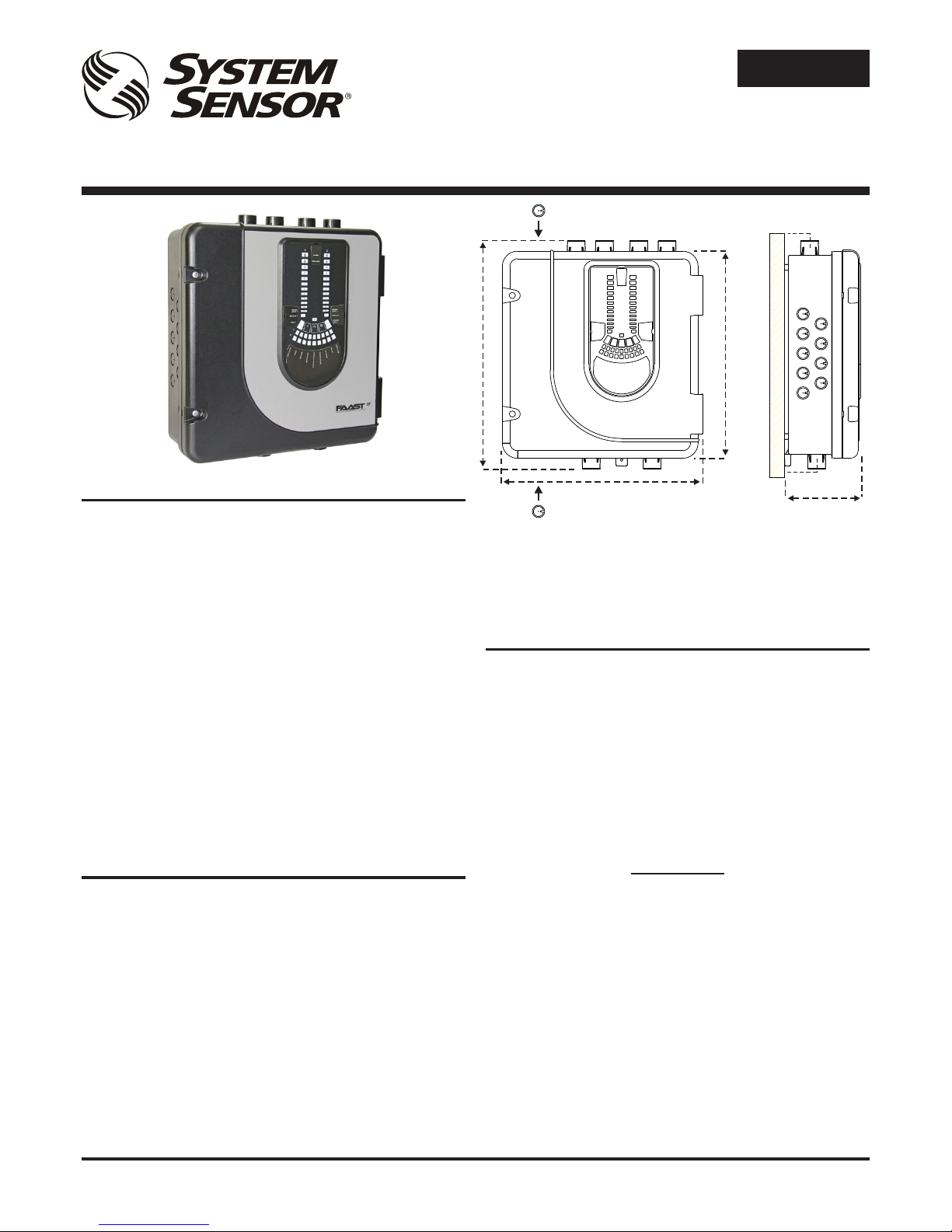
Exterior Dimensions: See Figure 1
Wiring: 0.5 mm² to 2 mm² max
Maximum Single Pipe Length: 100m (Classes A. B & C)
Maximum Number of Holes: See Table 1A
Pipe Spec (EN54-20 Compliance): to EN 61386
(Crush 1, Impact 1, Temp 31)
Outside Pipe Diameter: 25mm (nom) or 27mm (nom)
Shipping Weight: 6.5kg (inc sensors)
FIRE ALARM ASPIRATION SENSING TECHNOLOGY
®
QUICK INSTALLATION GUIDE
STAND-ALONE FAAST LT MODELS FL0111E FL0112E FL0122E
Figure 1: Dimensions and Knock-Outs
E N G L I S H
PARTS LIST
Description Quantity
FAAST LT unit 1
Mounting bracket 1
3-pin Terminal block 6
4-pin Terminal block 1
2-pin Terminal block 3
47 k-ohm EOL Resistor 2
USB Cable 1
Front Panel Labelling Pack 1
Installation Kit CD 1
Quick Installation Guide 1
Important Note
Aspirating Smoke Detectors supplied and installed within the
EU must conform to the EU Construction Products Directive
(89/106/EEC) and the related European Product Standard EN
54-20. FAAST LT has been tested and certied to ensure that it
conforms to the necessary Standards, but strict adherence to this
instruction guide is advised to ensure that the installation meets
the requirements of the CPD Directive
367 mm
135 mm
56 mm
44 mm
403 mm
356 mm
Page 2
D200-101-00
2
I56-3888-103
Pittway Tecnologica S.r.l. Via Caboto 19/3, 34147 TRIESTE, Italy
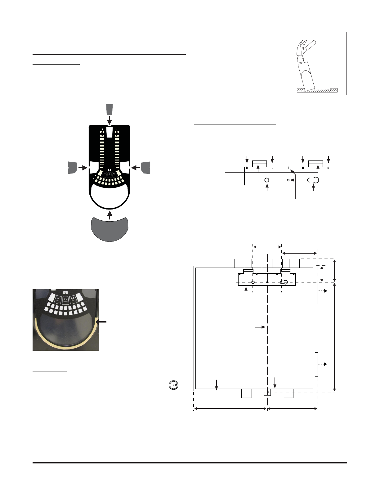
Figure 4: How to Knock Out Cable
Gland Holes
Figure 3: Remove Backing to
Stick Cover Down
When label A is in place, remove the protector from the bottom of
the clear cover to stick the cover down, as shown in Figure 3:
Cable Access
Knock out cable gland holes where required. The
location of the cable gland holes is shown in Figure 1,
represented by the icon:
This equipment and all associated pipe work must be installed in
accordance with all relevant codes and regulations.
PHYSICAL INSTALLATION
Front Panel Labels
The LT FL01 is shipped without the front panel labels xed in place.
This allows the installer to choose the language required for the
installation from the Front Panel Labelling Pack.
Figure 2 shows where the labels need to be placed:
Figure 6: Fasten the mounting bracket to the wall
Mounting the LT FL01 to the Wall
Figure 2: Placing the Front Panel Labels
2
10
3
1
4
5
6
7
8
9
2
10
3
1
4
5
6
7
8
9
INPUT
SENSOR
ASPIRATOR
ELBASID/MESY
TEMPERATURE
SOUNDER
FILTER
LOWFLOW
HIGHFLOW
S
T
FAULT
POWER
LEVEL2
SMOKE
MODULE2
MODULE1
LEVEL1
SMOKE
FAULT
ALARM
PREALARM
A
Figure 5: Mounting Bracket
FAAST LT
HANGING LUGS
INDICATES CENTRE OF ASPIRATING PIPES
FIXING HOLE FIXING HOLE
USE FOR PLUMB-LINE
90 mm
99 mm
59
329
212 mm
144 mm
41
mm
mm
mm
*
*
POSITION OF BRACKET
PLUMB LINE
BASE OUTLINE
OUTER DIMENSION OF UNIT
1 2 3 4 5 6 7 8 9 10 11 1213141516 1718
* Minimum clearance required from hinges to open door = 35 mm.
Page 3
D200-101-00
3
I56-3888-103
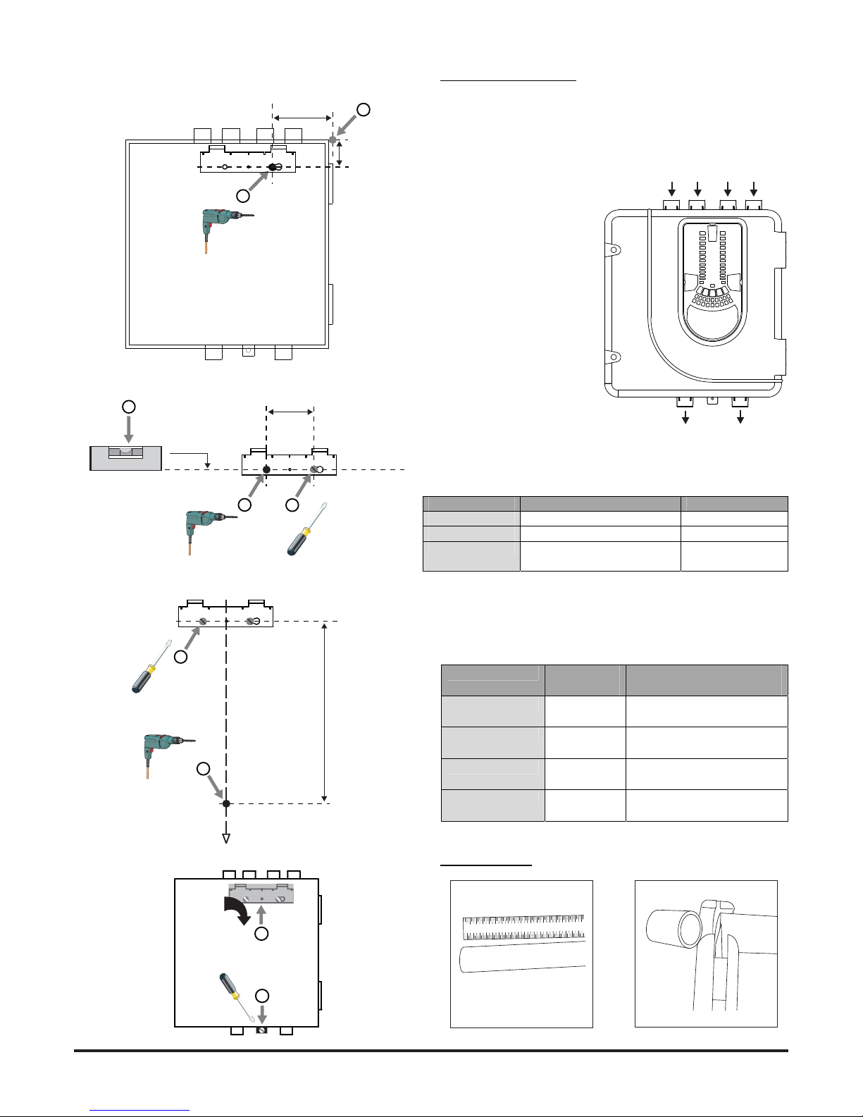
Figure 7: Sequence (1 to 9) to Mount the Detector on the Bracket
Pipe Installation
1 2 3 4 5 6 7 8 9 10111213141516
1718
1 2 3 4 5 6 7 8 9 101112131415161718
99 mm
41
1
2
mm
90 mm
4
3
0.00
o
5
329 mm
6
7
7a
7b
7c
7d
8
9
21
Pipe Hole Conguration
Figure 8 below shows the pipe holes available on the unit. Each
unit has 2 pipe holes per channel (so if installing a 1 channel unit,
holes 3 and 4 do not function). Use Table 1 to locate the holes
required for the installation:
1
2
3
4
5
6
Figure 8: Pipe Holes
FAASTLTMODEL INLETPIPEHOLE OUTLETPIPEHOLE
FL0111E 1&2,or1or2 5
FL0112E 1&2,or1or2 6
FL0122E Channel1‐1&2,or1or2
Channel2–3&4,or3or456
Table 1: Pipe Holes Used for Each FAAST LT Model
Note 1: Pipe holes not used should be kept sealed.
Note 2: Do NOT glue pipes into the pipe holes.
Table 1a: Maximum Number of Pipe Holes Allowed Per Channel
All gures quoted using highest (level 1) sensitivity
CLASS PIPELENGTH
(m)
MAXNUMBEROFHOLES
PERCHANNEL
C 100 18(10x2.5mm,8x3mm) +
3mmnonsensingendhole)
B 100 6 (4x4mm,2x5mmincend
hole)
A 100 2 x6mm (+6mmnon
sensingendhole)
A 80 3(1x5mm,2x6mm inc end
hole)
Page 4

D200-101-00
4
I56-3888-103
Pittway Tecnologica S.r.l. Via Caboto 19/3, 34147 TRIESTE, Italy
WIRING INSTALLATION
Power, Alarm and Control Connections
Figure 9: Inside the Detector
CHANNEL 2 FILTER
POWER AND
ALARM
CONNECTIONS
CHANNEL 1 FILTER
USB PORT
SENSOR COVER
POSITION FOR TEST MAGNET
POSITION FOR TEST MAGNET
Exhaust Pipe
SAMPLING AREA
SAMPLING AREA
1 2 3 4 5 6 7 8 9 101112 131415161718
1 2 3 4 5 6 7 8 9 101112 131415161718
5 6
EARTH BAR
MOUNT
EARTH BAR
MOUNT
EARTH BAR
(OPTIONAL)
1 2 3 4 5 6 7 8 9 101112 131415161718
1 2 3 4 5 6 7 8 9 101112 131415161718
3 4
Note 1: All wiring should comply with local
requirements and regulations.
Note 2: Panel wiring must observe the
recommendations of the panel manufacturer
Page 5

D200-101-00
5
I56-3888-103
Table 2: Wiring Terminal Designations
(Note - Terminals marked CH2 will only be available on 2 channel
models)
POWERING UP
Using Default Settings
1. Connect a suitable 24VDC supply (complying with European
Standard EN 54-4) to pins 1 and 2 on terminal block T1 (See
Table 2)
2. Check the voltage at the connector. Make sure it is within the
required voltage range.
3. If the voltage is within the specied range, connect the power
connector to the unit.
4. Close and secure the housing door; verify the fan starts up and
air ows out of the exhaust port. The unit takes 1-3 minutes to
initialise and stabilise in normal mode.
Conguring Other Options
To change any of the default options, it will be necessary to
connect the detector to a PC/laptop with the PipeIQLT software
installed; see USB connection section later in this guide for
more information on this (and the FAAST LT Advanced Setup and
Control Guide).
Table 3: Relays
No. Function
1 Ext Power In +
Primary PSU
T1
2 Ext Power In -
Primary PSU
3 Aux Power In +
Not used in default
4 Aux Power In -
Not used in default
5 NC Alarm Relay
CH1
T2
6 C Alarm Relay
CH1
7 NO Alarm Relay
CH1
8 NC Alarm Relay
CH2
T3
9 C Alarm Relay
CH2
10 NO Alarm Relay
CH2
11 NC Fault Relay
CH1
T4
12 C Fault Relay
CH1
13 NO Fault Relay
CH1
14 NC Fault Relay (AUX)
CH2
T5
15 C Fault Relay (AUX)
CH2
16 NO Fault Relay (AUX)
CH2
17 Sounder Output 1 -
47 k-ohm EOL Resistor T6
18 Sounder Output 1 +
19 Sounder Output 2 -
47 k-ohm EOL Resistor T7
20 Sounder Output 2 +
21 Configurable Input +
(Reset)
Default is active = short circuit
(unsupervised)
T8
22 Configurable Input -
(Reset)
23 NC Pre-Alarm Relay
CH1
T9
24 C Pre-Alarm Relay
CH1
25 NO Pre-Alarm Relay
CH1
26 NC Pre-Alarm Relay
CH2
T10
27 C Pre-Alarm Relay
CH2
28 NO Pre-Alarm Relay
CH2
RELAY ACTI ON: NOTES
ALARM 1 or 2 Set ON when ALARM CONDITION is met
on a channel
Default condition = Level 1. Alarm state is
latched as default. A manual RESET is
necessary to deactivate LED and relay.
PRE-ALARM 1 or 2 Set ON when PRE-ALARM CONDITION
is met on channel.
Default condition = Level 1.
FAULT 1 or 2 When FAULT CONDITION on Ch1 or Ch2
or a common FAULT occurs. Fault is also
indicated when in SERVICE mode and
when the unit is unpowered.
Fault state is not latched (default)
SOUNDER 1 or 2 Set ON when a channel is in ALARM /
PRE-ALARM. Sounder 1 corresponds to
Ch1 and Sounder 2 corresponds to Ch2
Default condition = set on in ALARM.
EXTERNAL RESET
The default setting for the congurable external input is Device
Reset (terminal block T8). A short circuit connection between these
terminals will cause the FAAST LT unit to perform a reset.
Page 6

D200-101-00
6
I56-3888-103
Pittway Tecnologica S.r.l. Via Caboto 19/3, 34147 TRIESTE, Italy
Figure 10: Front Panel Display
10b: FL0112E 1 Channel Detector (2 Sensors)
10a: FL0111E 1 Channel Detector (1 Sensor)
FRONT PANEL
The front panel will be different depending on which of the 3 FL01
models is being installed, and each is shown below.
The following information is displayed:
• Detector Status: Normal, Alarm, Fault or Isolate
• Alarm Level; Alarm, Pre-Alarm
• Particulate Levels; 1-9
• Flow Level
• Test, Reset and Disable Buttons
S
EN
SO
R
A
S
P
I
R
A
T
O
R
D
R
IF
T
C
O
M
P
E
N
S
A
T
I
O
N
TEMPERATURE / INPUT
DISABLE / SYSTEM
S
O
U
N
D
E
R
F
IL
TE
R
L
O
W
F
L
O
W
H
IG
H
F
L
O
W
INITIALIZATION
LEVEL 1
SMOKE
FAULT
FAULT
POWER
LEVEL 2
SMOKE
INITIALIZATION
ALARM
PREALARM
2
10
3
1
4
5
6
7
8
9
2
10
3
1
4
5
6
7
8
9
ALARM
PREALARM
SENSOR
ASPIRATOR
DRIFT COMPENSATION
DISABLE / SYSTEM
SOUNDER
FILTER
LOW FLOW
HIGH FLOW
INITIALIZATION
LEVEL
SMOKE
FAULT
FAULT
POWER
2
10
3
1
4
5
6
7
8
9
TEMPERATURE / INPUT
SENSOR
ASPIRATOR
DRIFT COMPENSATION
DISABLE / SYSTEM
SOUNDER
FILTER
LOW FLOW
HIGH FLOW
INITIALIZATION
LEVEL
SMOKE
FAULT
FAULT
POWER
ALARM
PREALARM
2
10
3
1
4
5
6
7
8
9
TEMPERATURE / INPUT
10c: FL0122E 2 Channel Detector
Page 7

D200-101-00
7
I56-3888-103
Table 4: Front Panel Indicators and Fault Descriptions
FAULT
POWER
LEVEL 2
SMOKE
INITIALIZATION
ALARM
PREALARM
2
10
3
1
4
5
6
7
8
9
2
10
3
1
4
5
6
7
8
9
Figure 11: User Interface Buttons
Front Panel Buttons
The front panel has 3 user buttons: TEST, RESET and DISABLE.
These buttons are used to enter the pass-code which then allows
the user to carry out simple test functions.
Note: In Remote Maintenance and Service Mode, these buttons
are always disabled.
INDICATOR ACTION WARNING OR TROUBLE COMMENT / ACTION
CHANNEL 1/2 ALARM ON Red, Channel is in alarm (relay is
set)
No delay with default settings
1 BLINK Green, when sensor is polled Not in alarm
CHANNEL 1/2 PRE-
ALARM
ON Channel is in pre-alarm (relay is
set)
SMOKE LEVEL ON Led number indicates sensor
alarm level reached
Only numbers 1 – 9 used
INITIALIZATION ON FAAST LT is in initialization
FAULT ON Common or multiple faults
1 BLINK Fault delay Default = 60s.
POWER ON FAAST LT is powered
POWER FAULT ON Low power alert / high power fault Check the power supply voltage.
CHANNEL FLOW
INDICATORS 1/2
ON The LED indicates the air flow for
a channel:
- Centre = normal flow
- Left = flow low;
(-20% at extreme)
- Right = flow high;
(+20% at extreme)
On 2 channel unit:
Upper row = Ch1
Lower row = Ch2
LOW FLOW ON Low flow fault Check filter; check pipe network for blockages.
SENSOR 1 BLINK Sensor initialization fault Try to restart device.
Replace faulty sensor.
2 BLINKS Sensor communication fault Check sensor addresses and installation; replace
sensor.
ASPIRATOR ON Air flow sensor fault Try to restart device.
1 BLINK Flow initialization fault Check filter; check pipe network for blockages. Try
to restart the device.
2 BLINKS Fan fault Try to restart device.
DRIFT COMPENSATION 1 BLINK Drift compensation, 1st alert Clean sensor
2 BLINKS Drift compensation, 2nd alert Clean sensor
3 BLINKS Drift compensation limit warning Sensor needs urgent maintenance
TEMPERATURE 1 BLINK Low temperature alert Check the air flow temperature
2 BLINKS High temperature alert Check the air flow temperature
INPUT 1 BLINK External input fault Not used with default settings
DISABLE 1 BLINK Alarms, faults & alerts not
reported
Returns to Maintenance then Normal operation
after 60min (default)
SYSTEM 1 BLINK Wrong configuration Flashes all FAULT LEDs. Try to restart device.
2 BLINKS EEPROM fault Check power supply voltage. Try to restart device
3 BLINKS Real time clock fault RTC is corrupted or time reading failed.
SOUNDER 1 BLINK Sounder fault Check the sounder circuit and the EOL
FILTER 1 BLINK Filter alert at set date No date set as default
HIGH FLOW ON High flow fault Check pipe network for breaks or leaks.
In case of simultaneous alerts/faults on the same LED, priority order is: ON (Highest), 1 blink, 2 blinks, 3 blinks (Lowest)
Page 8

D200-101-00
8
I56-3888-103
Pittway Tecnologica S.r.l. Via Caboto 19/3, 34147 TRIESTE, Italy
Password Sequence to Enter Maintenance Mode
Press and hold RESET; Left ow indicator will turn yellow, then
green.
Release RESET and FAULT indicator will switch on green. The
left ow indicator will blink green indicating the device is ready for
the rst digit.
Press DISABLE to increment the LEDs 1…9; press TEST to select
a digit.
The ashing airow segment will turn solid green and the next
segment will begin to ash indicating set the next digit. When the
4th digit is selected, all 4 airow segments are turned off. If the
password is accepted the FAULT indicator will remain green and
the unit enters Maintenance mode. If the password is incorrect
the FAULT indicator ashes yellow and the unit remains in Normal
mode. The Default password in 3111.
If no button is pressed for 10s during the password sequence, the
unit returns to Normal mode. If there is no activity in Maintenance
mode for 5 minutes (default), the FAULT indicator blinks green for
15s and then the unit returns to the Normal state.
TESTING
Magnet Test
The alarm signalling can be tested for functionality by placing a
test magnet in the position shown in Figure 9 (displayed earlier in
the guide). This method does not test the air ow in the pipe-work.
Smoke Testing
The system alarm response can be tested for functionality
using smoke. The choice of smoke source is dependant on the
installation but in all cases the smoke must be present for the
duration of the test. Smoke pellets or matches can be used close
to the sampling point to introduce smoke particulates into the
system. It is recommended that smoke with a particulate life cycle
of greater than 120s should be used – standard aerosol sprays for
point detector testing do not work well on aspirated systems.
Fault Testing
Simulate a fault on the detector (for example, block the outlet pipe)
and check that a fault is signalled on both the front panel of the unit
and at the CIE (Fire Panel).
Table 5: Front Panel Buttons
SERVICE
WARNING
Isolate the aspirating detector from the re alarm system to prevent
any unwanted alarms when opening the front door of the unit.
Make sure all power is removed from the system before removing
any covers.
Service Mode
Opening the cabinet door during normal operation will cause the
unit to enter Service Mode. The FILTER LEDs will blink, the unit will
switch off power to the fans and the fault relay will indicate a fault.
When the cabinet door is closed, the unit restarts automatically.
Filters
Periodic cleaning or replacement of the lters will be required.
The lters are located inside the cabinet at the top of the unit (see
Figure 9 displayed earlier in the guide) and are removed as shown
in the sequence below:
FAULT
POWER
LEVEL 2
SMOKE
INITIALIZATION
ALARM
PREALARM
2
10
3
1
4
5
6
7
8
9
FAULT
POWER
LEVEL 2
SMOKE
INITIALIZATION
2
10
3
1
4
5
6
7
8
9
FAULT
POWER
LEVEL 2
SMOKE
INITIALIZATION
ALARM
PREALARM
2
10
3
1
4
5
6
7
8
9
2
10
3
1
4
5
6
7
8
9
1
2
3
BUTTON NORMAL Mode MAINTENANCE Mode
RESET
When pressed for 2 s, starts PASSWORD
PROCEDURE to enter Maintenance
mode.
When pressed for 2 s latched alarms, faults and
sounders (relays) are reset
In DISABLE Mode, if pressed for 2 s unit will exit from
DISABLE Mode but remains in MAINTENANCE Mode
DIS ABLE
Used to increment Password digits in
PASSWORD PROCEDURE
When pressed for 2 s, device enters DISABLE Mode
for 60 minutes (default). (Alarms, alerts and faults not
reported).
(To exit DISABLE Mode see RESET)
TEST
Used to confirm password in PASSWORD
PROCEDURE. Default Password = 3111
When pressed for 2 s and released, both sensor will
simulate alarm
When pressed for 4 s and released, sensor #1 will
simulate alarm
When pressed for 6 s and released, sensor #2 will
simulate alarm
COMBINATIONS
RESET + DISABLE
When pressed for 2 s, shows fan speed
(on smoke level scales) for a preset time.
When pressed for 2 s, shows fan speed (on smoke
level scales) for preset time.
RESET + TEST
No action When pressed for 2 s, turns off sounders
RESET + TEST + DISABLE
No action When pressed for 2 s, unit exits from MAINTENANCE
Mode
FOAM GASKET
Page 9

D200-101-00
9
I56-3888-103
Either replace the lter assembly or carefully brush off the
accumulated dust.
Note: If replacing the lter, remove the foam gasket from the old
lter and place onto the new lter. When placing the new lter into
the slot, ensure that the gasket is correctly aligned.
Ret the lter, close and secure the cabinet door. The unit will
initialise and restart.
Smoke Sensors
The smoke sensors are located under the sensor cover (see Figure
9 displayed earlier in the guide). To access the sensors, follow the
sequence below:
Do NOT interchange the devices and do NOT alter the rotary
address switch settings on the sensors. If replacing a sensor,
ensure that the address set on the new sensor is the same as on
the sensor being replaced.
LASER SAFETY INFORMATION
The detector contains a Class 1 laser product. Radiation emitted
inside the smoke sensor is completely contained within its housings
and protective covers during all phases of operation.
USB CONNECTION
PC connectivity is provided by an on board USB B socket located
centrally between the lter and the sensor (see Figure 9 displayed
earlier in the guide). The USB interface allows access to a range
of additional options, via the PipeIQLT application software, when
connected to a PC. The USB connecting cable should be removed
during normal operation.
1 2
3
PipeIQ™LT QUICK START INSTRUCTIONS
Overview of PipeIQLT
The PipeIQLT software program is a convenient and powerful
Windows® based application that can be used to quickly and
accurately design pipe networks, generate conguration parameters
for correct set-up and operation, and facilitate commissioning and
monitoring of the performance of FAAST LT Aspiration devices.
PipeIQLT provides a graphical interface on a PC to:
• Develop and verify the performance of pipe network solutions.
• Congure the design parameters to suit local re codes and
standards.
• Generate Pipe Layouts, BoMs, Conguration and Event Log
Reports.
• Control, Test and Monitor FAAST LT devices.
There is a comprehensive Help Menu to guide the user through
the different windows and options. The contents have a detailed
index and a versatile search facility to locate relevant topics.
Minimum System Requirements
Microsoft Windows XP SP3 or Windows 7
1 GB of RAM.
Graphics hardware with 128 MB of memory and support for
OpenGL 2.0 or later.
5 GB of free hard disc space
Installing PipeIQLT
PipeIQLT is supplied on a mass storage device with each
FAAST LT unit, or it can be accessed as a download from www.
systemsensoreurope.com.
To install from the mass storage device
Insert and view the removable storage device. Click on PipeIQLT
Setup:
Click OK and follow the instructions (see: PipeIQLT Setup and
Installation Wizard section below).
To install from the website
Click on the link to PipeIQLT at www.systemsensoreurope.com.
Click on PipeIQLT download. The download security warning will
appear. Select Save, then click OK.
When the download completes, click Run to display the above
dialog box. Click OK and follow the instructions (see: PipeIQLT
Setup and Installation Wizard section below).
PipeIQLT Setup and Installation Wizard
When the below dialog box appears, click Setup to start the wizard:
Page 10

D200-101-00
10
I56-3888-103
Pittway Tecnologica S.r.l. Via Caboto 19/3, 34147 TRIESTE, Italy
Click Next and follow the on-screen instructions.
Unless changed, the install wizard will create and store les at the
following locations:
When installation is complete, the wizard will
automatically create a shortcut icon on the PC
desktop.
It will be necessary to re-boot the PC in order to
run PipeIQLT.
Quitting
Exiting the program closes the application completely.
To quit the PipeIQLT application, click X in the upper-right corner
of the window.
Or click Exit from the File menu.
PipeIQLT can be uninstalled from the computer in the normal way
for your operating system.
Launching
To launch the PipeIQLT application, double click the PipeIQLT icon
on the desktop.
Or
click Start (bottom left corner of the Windows screen) and then
select PipeIQLT from the programs list.
When the application opens, it is possible to start a new project, or
to monitor or modify an existing project. Use the File menu to select
New or Open. Choose from the Pipe Design, Conguration or
Monitoring tabs to enter the required mode.
Set the detector to Maintenance mode. To communicate with
a FAAST LT detector, connect the USB port to a PC with an
appropriate cable.
EN54-20 : 2006
Class A B & C
Aspirating Smoke Detectors
0832
FL0111E: 0832-CPD-1990 12
FL0112E: 0832-CPD-1991 12
FL0122E: 0832-CPD-1992 12
Pittway Tecnologica S.r.l.
Via Caboto 19/3,
34147 Trieste, Italy
 Loading...