

Page 1
D200-101-00
1
I56-3888-105
DESCRIPTION
The LT FL01 Series is part of the Fire Alarm Aspiration Sensing
Technology® (FAAST) family. FAAST is an advanced re detection
system for use where early warning and very early warning are a
requirement. The system continuously draws air from the controlled
environment through a series of sampling holes to monitor the
environment for smoke particulate.
The FL01 is the stand-alone version of the FAAST LT range and is
available in 3 different models:
FL0111E - Has single channel capability with one laser smoke
sensor.
FL0112E - Has single channel capability with two laser smoke
sensors in a common chamber for coincidence
detection.
FL0122E - Has two channel capability with two laser smoke
sensors in separate chambers. (One sensor for each
channel).
This guide provides information for mounting and basic installation
using the unit’s default factory settings. For more extensive
information please see the FAAST LT Advanced Setup and Control
Guide - reference D200-100-00.
SPECIFICATIONS
Electrical Characteristics
Voltage Range: 18.5 - 31.5 VDC
Supply Current: 1 Channel: 170mA (typical); 360mA (max) @
24 VDC 25oC (excluding sounders)
2 Channel: 270mA (typical); 570mA (max) @
24 VDC 25oC (excluding sounders)
Congurable Input: Activation Time: 2s (min)
Relay Contact Ratings: 2.0 A @ 30 VDC, 0.5A @ 30 VAC
Environmental Ratings
Temperature: -10°C to 55°C
Relative Humidity: 10% to 93% (non-condensing)
IP Rating: 65
Mechanical
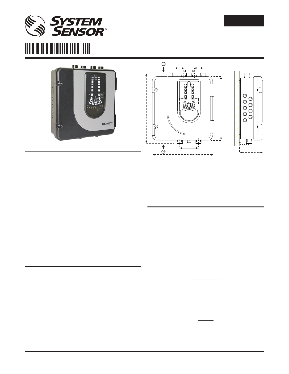
Exterior Dimensions: See Figure 1
Wiring: 0.5 mm² to 2 mm² max
Maximum Single Pipe Length: 100m (Classes B & C)
Maximum Branched Pipe Length: 160m (2 x 80m, Class C)
Maximum Number of Holes: See Table 1A
Pipe Spec (EN54-20 Compliance): to EN 61386
(Crush 1, Impact 1, Temp 31)
Outside Pipe Diameter: 25mm (nom) or 27mm (nom)
Shipping Weight: 6.5kg (inc sensors)
FIRE ALARM ASPIRATION SENSING TECHNOLOGY
®
QUICK INSTALLATION GUIDE
STAND-ALONE FAAST LT MODELS FL0111E FL0112E FL0122E
Figure 1: Dimensions and Knock-Outs
E N G L I S H
PARTS LIST
Description Quantity
FAAST LT unit 1
Mounting bracket 1
3-pin Terminal block 6
4-pin Terminal block 1
2-pin Terminal block 3
47 k-ohm EOL Resistor 2
USB Cable 1
Front Panel Labelling Pack 1
Wiring Diagram Label 1
Installation Kit CD 1
Quick Installation Guide 1
Important Note
Aspirating Smoke Detectors supplied and installed within the
EU must conform to the EU Construction Products Regulation
(CPR) 305/2011 and the related European Product Standard EN
54-20. FAAST LT has been tested and certied to ensure that it
conforms to the necessary Standards, but strict adherence to this
instruction guide is advised to ensure that the installation meets
the requirements of the CPR.
Warning
The performance of this system is dependent upon the pipe
network. Any extension or modication to the designed
installation may cause improper operation. The operational
effects of such changes need to be veried using the PipeIQ
2 design software.
367 mm
135 mm
56 mm
44 mm
403 mm
356 mm
50 mm 50 mm
60 mm
110 mm
I 56- 3888- 105
Page 2
D200-101-00
2
I56-3888-105
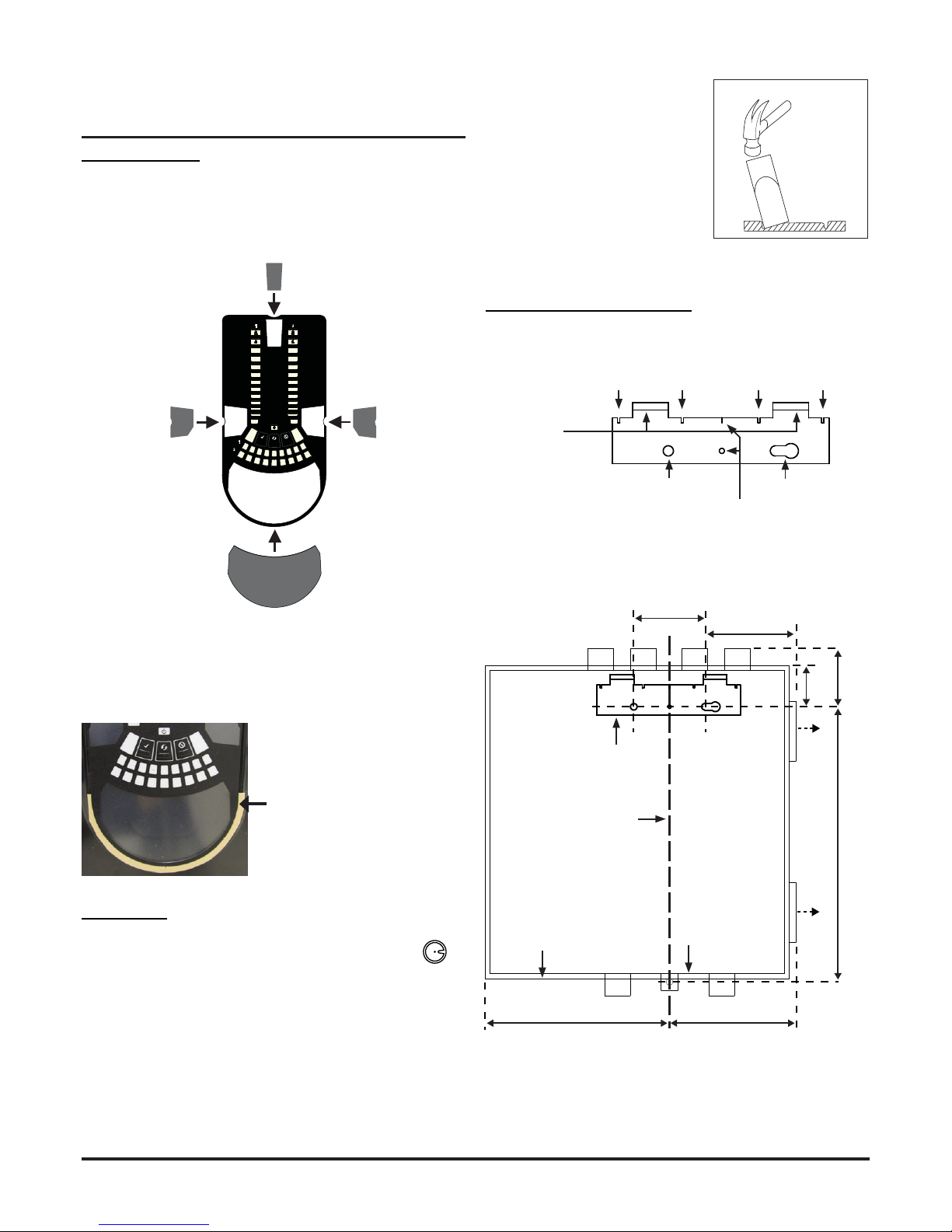
Figure 4: How to Knock Out Cable
Gland Holes
Figure 3: Remove Backing to
Stick Cover Down
When label A is in place, remove the protector from the bottom of
the clear cover to stick the cover down, as shown in Figure 3:
Cable Access
Knock out cable gland holes where required. The
location of the cable gland holes is shown in Figure 1,
represented by the icon:
This equipment and all associated pipe work must be installed in
accordance with all relevant codes and regulations.
PHYSICAL INSTALLATION
Front Panel Labels
The LT FL01 is shipped without the front panel labels xed in place.
This allows the installer to choose the language required for the
installation from the Front Panel Labelling Pack.
Figure 2 shows where the labels need to be placed:
Figure 6: Fasten the mounting bracket to the wall
Mounting the LT FL01 to the Wall
Figure 2: Placing the Front Panel Labels
2
10
3
1
4
5
6
7
8
9
2
10
3
1
4
5
6
7
8
9
INPUT
SENSOR
ASPIRATOR
ELBASID/MESY
TEMPERATURE
SOUNDER
FILTER
LOWFLOW
HIGHFLOW
S
T
FAULT
POWER
LEVEL2
SMOKE
MODULE2
MODULE1
LEVEL1
SMOKE
FAULT
ALARM
PREALARM
A
Figure 5: Mounting Bracket
FAAST LT
HANGING LUGS
INDICATES CENTRE OF ASPIRATING PIPES
FIXING HOLE FIXING HOLE
USE FOR PLUMB-LINE
90 mm
99 mm
59
329
212 mm
144 mm
41
mm
mm
mm
*
*
POSITION OF BRACKET
PLUMB LINE
BASE OUTLINE
OUTER DIMENSION OF UNIT
1 2 3 4 5 6 7 8 9 101112131415161718
* Minimum clearance required from hinges to open door = 35 mm.
Page 3

D200-101-00
3
I56-3888-105
Figure 7: Sequence (1 to 9) to Mount the Detector on the Bracket
Pipe Installation
1 2 3 4 5 6 7 8 9 10 1112 13141516
1718
1 2 3 4 5 6 7 8 9 10 1112 131415161718
99 mm
41
1
2
mm
90 mm
4
3
0.00
o
5
329 mm
6
7
7a
7b
7c
7d
8
9
21
Pipe Hole Conguration
Figure 8 below shows the pipe holes available on the unit. Each
unit has 2 pipe holes per channel connected together like a T-Piece.
If using a 1 channel unit, holes 3 and 4 do not function. Use Table
1 to locate the holes required for the installation:
Figure 8: Pipe Holes
FAASTLTMODEL INLETPIPEHOLE OUTLETPIPEHOLE
FL0111E 1and/or2 5
FL0112E 1and/or2 6
FL0122E Channel1‐1and/or2
Channel2–3and/or4
5
6
Table 1: Pipe Holes Used for Each FAAST LT Model
Note 1: Pipe holes not used should be kept sealed.
Note 2: Do NOT glue pipes into the pipe holes.
Table 1a: Maximum Number of Pipe Holes Allowed Per Channel
All gures quoted using highest (level 1) sensitivity
1
2
3
4
5
6
CHANNEL 1
CHANNEL 2 (ONLY FUNCTION
ON 2 CHANNEL UNITS)
CHANNEL 1 (NOT
USED FOR COMMON
CHAMBER UNIT)
CHANNEL 2 (ONLY
FUNCTIONS ON 2
CHANNEL AND COMMON
CHAMBER UNITS)
CLASS PIPELENGTH
(m)
MAXNUMBEROFHOLESPER
CHANNEL
C 100 18(5x2mm,6x2.5mm,3x3mm,
3x3.5mmand1x4mm)+4mm
nonsensingendhole
C 160(2x80)
UsingT‐Piece
9holesperbranch(3x2.5mm,6x
3mm)+3mmnonsensingendhole
B 100 6(2x3.5mm,2x4mm,2x5mm
incendhole)
A 80 3(1x5mm,2x6mmincendhole)
Page 4

D200-101-00
4
I56-3888-105
WIRING INSTALLATION
Power, Alarm and Control Connections
Figure 9: Inside the Detector
CHANNEL 2 FILTER
POWER AND
ALARM
CONNECTIONS
CHANNEL 1 FILTER
USB PORT
SENSOR COVER
POSITION FOR
TEST MAGNET
Exhaust Pipe
1 2 3 4 5 6 7 8 9 10 11 12131415161718
1 2 3 4 5 6 7 8 9 10 11 12131415161718
5 6
EARTH BAR
MOUNT
EARTH BAR
MOUNT
F-LT-EB
EARTH BAR
(OPTIONAL)
1 2 3 4 5 6 7 8 9 10 11 12131415161718
1 2 3 4 5 6 7 8 9 10 11 12131415161718
3 4
Note 1: All wiring should comply with local
requirements and regulations.
Note 2: Panel wiring must observe the
recommendations of the panel manufacturer
PLACE
WIRING
LABEL
HERE
If the FAAST LT door is closed for a long time
(especially at high temperatures) it may be
necessary to use a at-bladed screwdriver
between the two tabs at the top of the unit to
lever open the door (as shown above).
SAMPLING AREA
SAMPLING AREA
Whenever the FAAST LT is installed outside the risk area, return of
the exhaust air back into the protected area can reduce ow faults
due to pressure difference.
!
MODULE MOUNT
MODULE MOUNT
F-LT-PMB
MODULE MOUNT
KIT (OPTIONAL)*
*If required, an input/output module
can be installed into the FAAST LT
unit. The optional module mount kit
(F-LT-PMB) will be needed for this.
Page 5

D200-101-00
5
I56-3888-105
Table 2: Wiring Terminal Designations
(Note - Terminals marked CH2 will only be available on 2 channel
models)
Table 3: Relays
No. Function
1 Ext Power In +
Primary PSU
T1
2 Ext Power In -
Primary PSU
3 Aux Power In +
Not used in default
4 Aux Power In -
Not used in default
5 NC Alarm Relay
CH1
T2
6 C Alarm Relay
CH1
7 NO Alarm Relay
CH1
8 NC Alarm Relay
CH2
T3
9 C Alarm Relay
CH2
10 NO Alarm Relay
CH2
11 NC Fault Relay
CH1
T4
12 C Fault Relay
CH1
13 NO Fault Relay
CH1
14 NC Fault Relay (AUX)
CH2
T5
15 C Fault Relay (AUX)
CH2
16 NO Fault Relay (AUX)
CH2
17 Sounder Output 1 -
47 k-ohm EOL Resistor T6
18 Sounder Output 1 +
19 Sounder Output 2 -
47 k-ohm EOL Resistor T7
20 Sounder Output 2 +
21 Configurable Input +
(Reset)
Default is active = short circuit
(unsupervised)
T8
22 Configurable Input -
(Reset)
23 NC Pre-Alarm Relay
CH1
T9
24 C Pre-Alarm Relay
CH1
25 NO Pre-Alarm Relay
CH1
26 NC Pre-Alarm Relay
CH2
T10
27 C Pre-Alarm Relay
CH2
28 NO Pre-Alarm Relay
CH2
RELAY ACTION: NOTES
ALARM 1 or 2 Set ON when ALARM CONDITION is met
on a channel
Default condition = Level 1. Alarm state is
latched as default. A manual RESET is
necessary to deactivate LED and relay.
PRE-ALARM 1 or 2 Set ON when PRE-ALARM CONDITION
is met on channel.
Default condition = Level 1.
FAULT 1 or 2 When FAULT CONDITION on Ch1 or Ch2
or a common FAULT occurs. Fault is also
indicated when in SERVICE mode and
when the unit is unpowered.
Fault state is not latched (default)
SOUNDER 1 or 2 Set ON when a channel is in ALARM /
PRE-ALARM. Sounder 1 corresponds to
Ch1 and Sounder 2 corresponds to Ch2
Default condition = set on in ALARM.
Table 3a: Relay Electrical Specication
SPECIFICATION MIN MAX UNITS COMMENTS
Contact Rating 2
0.5
A
A
30 VDC resistive load
30 VAC resistive load
Life Time 105 Operations
1N6284CA
FAAST LT
FAAST LT
CL
FAAST LT
R
L/C
WARNING: Switching Inductive Loads
Inductive loads can cause switching surges, which may damage
the module relay contacts (see above).
To protect the relay contacts, connect a suitable Transient Voltage
Suppressor (for example 1N6284CA ) across the load as shown.
Alternatively, for unsupervised DC applications, t a diode with a
reverse breakdown voltage greater than 10 times the circuit voltage.
Fitting the Terminal Blocks
To insert the terminal blocks into the unit use the following method:
1 Insert a corner of the block into the slot (see a).
2 Push the length of the block into the slot until the block ‘clicks’
into place, the 2 upper hooks on the block should be visible
(see c).
a b c
Page 6

D200-101-00
6
I56-3888-105
Figure 10: Front Panel Display
10b: FL0112E 1 Channel Detector (2 Sensors)
10a: FL0111E 1 Channel Detector (1 Sensor)
FRONT PANEL
The front panel will be different depending on which of the 3 FL01
models is being installed, and each is shown below.
The following information is displayed:
• Detector Status: Normal, Alarm, Fault or Isolate
• Alarm Level; Alarm, Pre-Alarm
• Particulate Levels; 1-9
• Flow Level
• Test, Reset and Disable Buttons
S
EN
SO
R
A
S
P
I
R
A
T
O
R
D
R
IF
T
C
O
M
P
E
N
S
A
T
I
O
N
TEMPERATURE / INPUT
DISABLE / SYSTEM
S
O
U
N
D
E
R
F
IL
TE
R
L
O
W
F
L
O
W
H
IG
H
F
L
O
W
INITIALIZATION
LEVEL 1
SMOKE
FAULT
FAULT
POWER
LEVEL 2
SMOKE
INITIALIZATION
ALARM
PREALARM
2
10
3
1
4
5
6
7
8
9
2
10
3
1
4
5
6
7
8
9
ALARM
PREALARM
SENSOR
ASPIRATOR
DRIFT COMPENSATION
DISABLE / SYSTEM
SOUNDER
FILTER
LOW FLOW
HIGH FLOW
INITIALIZATION
LEVEL
SMOKE
FAULT
FAULT
POWER
2
10
3
1
4
5
6
7
8
9
TEMPERATURE / INPUT
SENSOR
ASPIRATOR
DRIFT COMPENSATION
DISABLE / SYSTEM
SOUNDER
FILTER
LOW FLOW
HIGH FLOW
INITIALIZATION
LEVEL
SMOKE
FAULT
FAULT
POWER
ALARM
PREALARM
2
10
3
1
4
5
6
7
8
9
TEMPERATURE / INPUT
10c: FL0122E 2 Channel Detector
POWERING UP
Using Default Settings
1. Connect a suitable 24VDC supply (complying with European
Standard EN 54-4) to pins 1 and 2 on terminal block T1 (See
Table 2)
2. Check the voltage at the connector. Make sure it is within the
required voltage range.
3. If the voltage is within the specied range, connect the power
connector to the unit.
4. Close and secure the housing door; verify the fan starts up and
air ows out of the exhaust port. The unit takes 1-3 minutes to
initialise and stabilise in normal mode.
EXTERNAL RESET
The default setting for the congurable external input is Device
Reset (terminal block T8). A short circuit connection between these
terminals will cause the FAAST LT unit to perform a reset.
Page 7

D200-101-00
7
I56-3888-105
Table 4: Front Panel Indicators and Fault Descriptions
FAULT
POWER
LEVEL 2
SMOKE
INITIALIZATION
ALARM
PREALARM
2
10
3
1
4
5
6
7
8
9
2
10
3
1
4
5
6
7
8
9
Figure 11: User Interface Buttons
Front Panel Buttons
The front panel has 3 user buttons: TEST, RESET and DISABLE.
These buttons are used to enter the pass-code which then allows
the user to carry out simple test functions.
Note: In Remote Maintenance and Service Mode, these buttons
are always disabled.
INDICATOR ACTION WARNING OR TROUBLE COMMENT / ACTION
CHANNEL 1/2
ALARM
ON Red Channel is in alarm (relay is set) No delay with default settings
1 BLINK Green when sensor is polled Not in alarm
CHANNEL 1/2 PRE-
ALARM
ON Yellow Channel is in pre-alarm (relay is
set)
SMOKE LEVEL ON Yellow Led number indicates sensor
alarm level reached
Only numbers 1 – 9 used
INITIALIZATION ON Yellow FAAST LT is in initialization
FAULT ON Yellow Common or multiple faults
1 BLINK Yellow Fault delay Default = 60s.
POWER ON Green FAAST LT is powered
POWER FAULT ON Yellow Low power alert / high power
fault
Check the power supply voltage.
CHANNEL FLOW
INDICATORS 1/2
ON Green The LED indicates the air flow
for a channel:
- Centre = normal flow
- Left = flow low;
(-20% at extreme)
- Right = flow high;
(+20% at extreme)
On 2 channel unit:
Upper row = Ch1
Lower row = Ch2
LOW FLOW ON Yellow Low flow fault Check filter; check pipe network for blockages.
SENSOR 1 BLINK Yellow Sensor initialization fault Try to restart device.
Replace faulty sensor.
2 BLINKS Yellow Sensor communication fault Check sensor addresses and installation;
replace sensor.
ASPIRATOR ON Yellow Air flow sensor fault Try to restart device.
1 BLINK Yellow Flow initialization fault Check filter; check pipe network for blockages.
Try to restart the device.
2 BLINKS Yellow Fan fault Try to restart device.
DRIFT
COMPENSATION
1 BLINK Yellow Drift compensation, 1st alert Clean sensor
2 BLINKS Yellow Drift compensation, 2nd alert Clean sensor
3 BLINKS Yellow Drift compensation limit warning Sensor needs urgent maintenance
TEMPERATURE 1 BLINK Yellow Low temperature alert Check the air flow temperature
2 BLINKS Yellow High temperature alert Check the air flow temperature
INPUT 1 BLINK Yellow External input fault Not used with default settings
DISABLE 1 BLINK Yellow Alarms, faults & alerts not
reported
Returns to Maintenance then Normal operation
after 60min (default)
SYSTEM 1 BLINK Yellow Wrong configuration Flashes all FAULT LEDs. Try to restart device.
2 BLINKS Yellow EEPROM fault Check power supply voltage. Try to restart
device
3 BLINKS Yellow Real time clock fault RTC is corrupted or time reading failed.
SOUNDER 1 BLINK Yellow Sounder fault Check the sounder circuit and the EOL
FILTER 1 BLINK Yellow Filter alert at set date No date set as default
HIGH FLOW ON Yellow High flow fault Check pipe network for breaks or leaks.
In case of simultaneous alerts/faults on the same LED, priority order is: ON (Highest), 1 blink, 2 blinks, 3 blinks (Lowest)
Page 8

D200-101-00
8
I56-3888-105
Password Sequence to Enter Maintenance Mode
Press and hold RESET; Left ow indicator will turn yellow, then
green.
Release RESET and FAULT indicator will switch on green. The
left ow indicator will blink green indicating the device is ready for
the rst digit.
Press DISABLE to increment the LEDs 1…9; press TEST to select
a digit.
The ashing airow segment will turn solid green and the next
segment will begin to ash indicating set the next digit. When the
4th digit is selected, all 4 airow segments are turned off. If the
password is accepted the FAULT indicator will remain green and
the unit enters Maintenance mode. If the password is incorrect
the FAULT indicator ashes yellow and the unit remains in Normal
mode. The Default password in 3111.
If no button is pressed for 10s during the password sequence, the
unit returns to Normal mode.
Exit from Maintenance Mode
To exit from the Maintenance mode, press the three front panel
user interface buttons TEST, RESET and DISABLE simultaneously
for 2 seconds. Alternatively, reset the unit using the Remote Input
(when set to default value) or power the device off and on again.
If there is no activity in Maintenance mode for 5 minutes (default),
the FAULT indicator blinks green for 15s and then the unit
automatically returns to the Normal state.
TESTING
Magnet Test
The alarm signalling can be tested for functionality by placing a
test magnet in the position shown in Figure 9 (displayed earlier in
the guide). This method does not test the air ow in the pipe-work.
Smoke Testing
The system alarm response can be tested for functionality
using smoke. The choice of smoke source is dependant on the
installation but in all cases the smoke must be present for the
duration of the test. Smoke pellets or matches can be used close
to the sampling point to introduce smoke particulates into the
system. It is recommended that smoke with a particulate life cycle
of greater than 120s should be used – standard aerosol sprays for
point detector testing do not work well on aspirated systems.
Table 5: Front Panel Buttons
Fault Testing
Simulate a fault on the detector (for example, block the outlet pipe)
and check that a fault is signalled on both the front panel of the unit
and at the CIE (Fire Panel).
SERVICE
WARNING
Isolate the aspirating detector from the re alarm system to prevent
any unwanted alarms when opening the front door of the unit.
Make sure all power is removed from the system before removing
any covers.
Service Mode
Opening the cabinet door during normal operation will cause the
unit to enter Service Mode. The FILTER LEDs will blink, the unit will
switch off power to the fans and the fault relay will indicate a fault.
When the cabinet door is closed, the unit restarts automatically.
Filters
Periodic cleaning or replacement of the lters will be required.
The lters are located inside the cabinet at the top of the unit (see
Figure 9 displayed earlier in the guide) and are removed as shown
in the sequence below:
FAULT
POWER
LEVEL 2
SMOKE
INITIALIZATION
ALARM
PREALARM
2
10
3
1
4
5
6
7
8
9
FAULT
POWER
LEVEL 2
SMOKE
INITIALIZATION
2
10
3
1
4
5
6
7
8
9
FAULT
POWER
LEVEL 2
SMOKE
INITIALIZATION
ALARM
PREALARM
2
10
3
1
4
5
6
7
8
9
2
10
3
1
4
5
6
7
8
9
1
2
3
FOAM GASKET
BUTTON NORMAL Mode MAINTENANCE Mode
RESET When pressed for 2 s, starts PASSWORD
PROCEDURE to enter Maintenance
mode.
When pressed for 2 s latched alarms, faults and
sounders (relays) are reset
In DISABLE Mode, if pressed for 2 s unit will exit from
DISABLE Mode but remains in MAINTENANCE Mode
DISABLE Used to increment Password digits in
PASSWORD PROCEDURE
When pressed for 2 s, device enters DISABLE Mode
for 60 minutes (default). (Alarms, alerts and faults not
reported).
(To exit DISABLE Mode see RESET)
TEST Used to confirm password in PASSWORD
PROCEDURE. Default Password = 3111
When pressed for 2 s and released, both sensors will
simulate alarm
When pressed for 4 s and released, sensor #1 will
simulate alarm
When pressed for 6 s and released, sensor #2 will
simulate alarm
Warning: Outputs will be activated by test
COMBINATIONS
RESET + DISABLE When pressed for 2 s, shows fan speed
(on smoke level scales) for a preset time.
When pressed for 2 s, shows fan speed (on smoke
level scales) for preset time.
RESET + TEST No action When pressed for 2 s, turns off sounders
RESET + TEST + DISABLE No action When pressed for 2 s, unit exits from MAINTENANCE
Mode
Page 9

D200-101-00
9
I56-3888-105
Either replace the lter assembly or carefully brush off the
accumulated dust.
Note: If replacing the lter, remove the foam gasket from the old
lter and place onto the new lter. When placing the new lter into
the slot, ensure that the gasket is correctly aligned.
Ret the lter, close and secure the cabinet door. The unit will
initialise and restart.
Smoke Sensors
The smoke sensors are located under the sensor cover (see Figure
9 displayed earlier in the guide). To access the sensors, follow the
sequence below:
Do NOT interchange the devices and do NOT alter the rotary
address switch settings on the sensors. If replacing a sensor,
ensure that the address set on the new sensor is the same as on
the sensor being replaced.
LASER SAFETY INFORMATION
The detector contains a Class 1 laser product. Radiation emitted
inside the smoke sensor is completely contained within its housings
and protective covers during all phases of operation.
WARNING
Using compressed air to clean the pipe system
High pressure air ushed through the system could damage
the fan, ensure that the FAAST LT unit is sealed or detached
from the system before commencing this procedure.
USB CONNECTION
PC connectivity is provided by an on board USB B socket located
centrally between the lter and the sensor cover (see Figure 9
displayed earlier in the guide). The USB interface allows access to
a range of additional options via the PipeIQ 2 application software
running on a PC.
Conguring Other Options
To change any of the default options, it will be necessary to connect
the detector to a PC/laptop with the PipeIQ 2 software installed;
see the FAAST LT Advanced Setup and Control Guide for further
information.
Note: The USB connecting cable should be removed during
normal operation.
1
2
3
System Sensor Europe
Pittway Tecnologica S.r.l.
Via Caboto 19/3
34147 TRIESTE
Italy
EN54-20 : 2006
Class A B & C
Aspirating Smoke Detectors
0832 12
FL0111E: DOP-ASP006
FL0112E: DOP-ASP007
FL0122E: DOP-ASP008
System Sensor Europe
Pittway Tecnologica S.r.l.
Via Caboto 19/3,
34147 Trieste, Italy
DoP Ref:
4
 Loading...