

Page 1
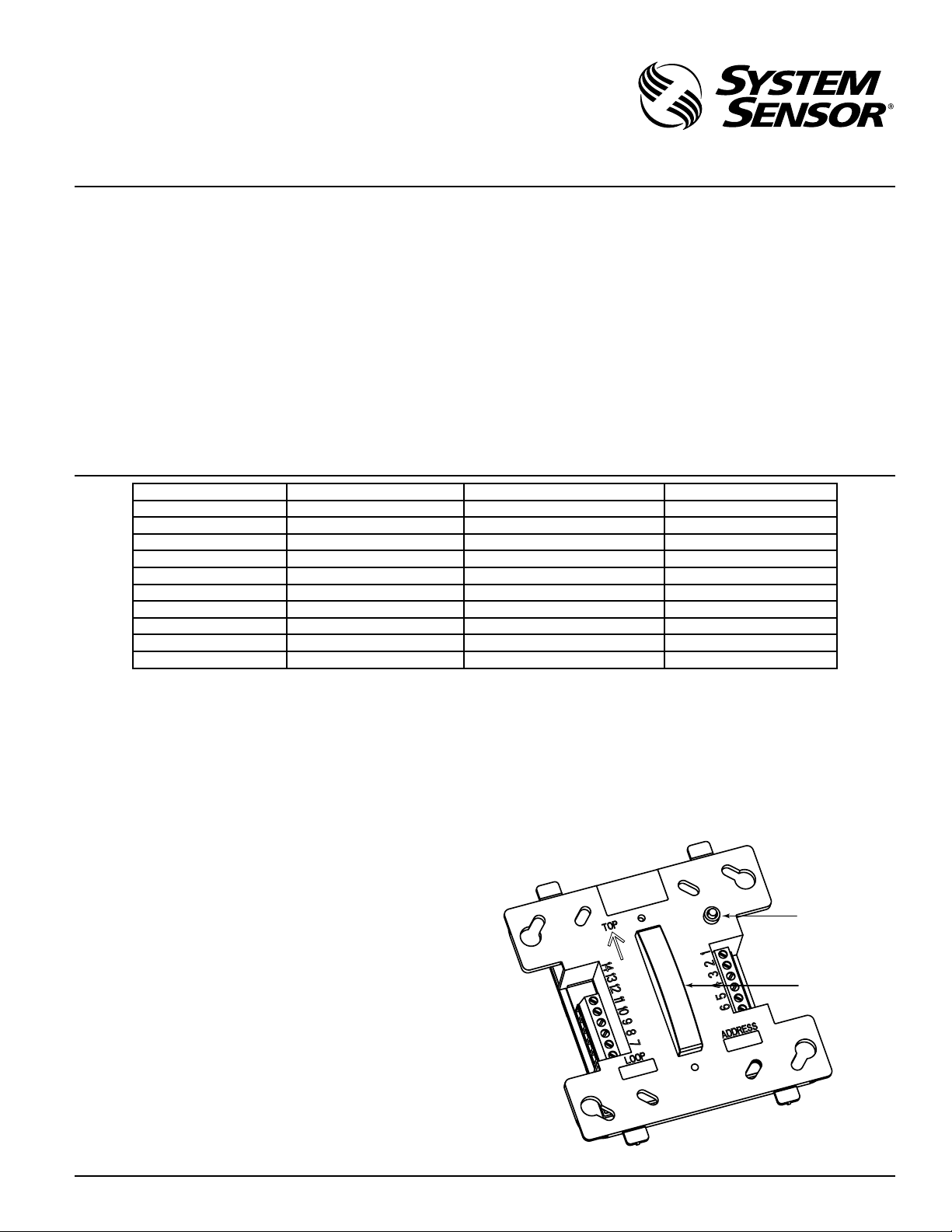
LED
INDICATOR
IR
RECEIVER
INSTALLATION AND MAINTENANCE INSTRUCTIONS
EM-1RI Relay Module
SPECIFICATIONS
Normal Operating Voltage: 15 to 30 VDC
Standby Current: 500 µA max. average (continuous broadcasts)
Alarm Current: 2.0 mA (red LED on)
Short Circuit Current
Dry Control Input: 30 µA max. Avg. (5VDC)
Maximum Resistance
Dry Contact Input: 100
Temperature Range: 32°F to 120°F (0°C to 49°C)
Humidity: 10 to 93% RH Non-condensing
Dimensions: 4.17˝ H x 4.26˝ W x 1.22˝ D
(106 mm H x 108 mm W x 31 mm D)
Accessories: Wall cover plate (included)
SMB500 Surface Mount Electrical Box
CB500 Control Module Barrier
CURRENT RATING MAXIMUM VOLTAGE LOAD DESCRIPTION APPLICATION
3 A 30 VDC Resistive Non-Coded
2 A 30 VDC Resistive Coded
.9 A 110 VDC Resistive Non-Coded
.9 A 125 VDC Resistive Non-Coded
.5 A 30 VDC Inductive (L/R=5ms) Coded
1 A 30 VDC Inductive (L/R=2ms) Coded
.3 A 125 VAC Inductive (PF=.35) Non-Coded
1.5 A 25 VAC Inductive (PF = .35) Non-Coded
.7 A 70.7 VAC Inductive (PF=.35) Non-Coded
2 A 25 VAC Inductive (PF=.35) Non-Coded
Ω
I56-2023-004
3825 Ohio Avenue, St. Charles, Illinois 60174
1-800-SENSOR2, FAX: 630-377-6495
www.systemsensor.com
NOTE: This module is not approved for use in the European Union, at or above 50VAC or 70VDC.
BEFORE INSTALLING
This information is included as a quick reference installation
guide. Refer to the appropriate control panel installation manual
for detailed system information. If the modules will be installed
in an existing operational system, inform the operator and local
authority that the system will be temporarily out of service.
NOTICE: This manual should be left with the owner/user of
this equipment.
GENERAL DESCRIPTION
Relay Module, Model EM-1RI, is to be designed for use in activation of the types of products that are generally connected to an intelligent fire alarm system. It provides two sets of form C contacts
that switch together (one DPDT relay). There is also an input that
is capable of monitoring a dry set of contacts for open or closed
conditions. The module also has on-board short circuit isolators
to prevent shorts on the signaling line circuit from disabling more
than one device on the intelligent loop.
COMPATIBILITY REQUIREMENTS
To ensure proper operation, this module shall be connected to a
listed compatible control panel.
MOUNTING
The module mounts directly to 4˝ square electrical boxes. The box
must have a minimum depth of 21⁄8˝. Modules must be mounted
with the arrow facing upward for proper operation of the IR programming tool. Surface mounted electrical boxes (SMB500) are
available from System Sensor.
C0166-00
D500-61-00 1 I56-2023-004
Page 2
WARNING
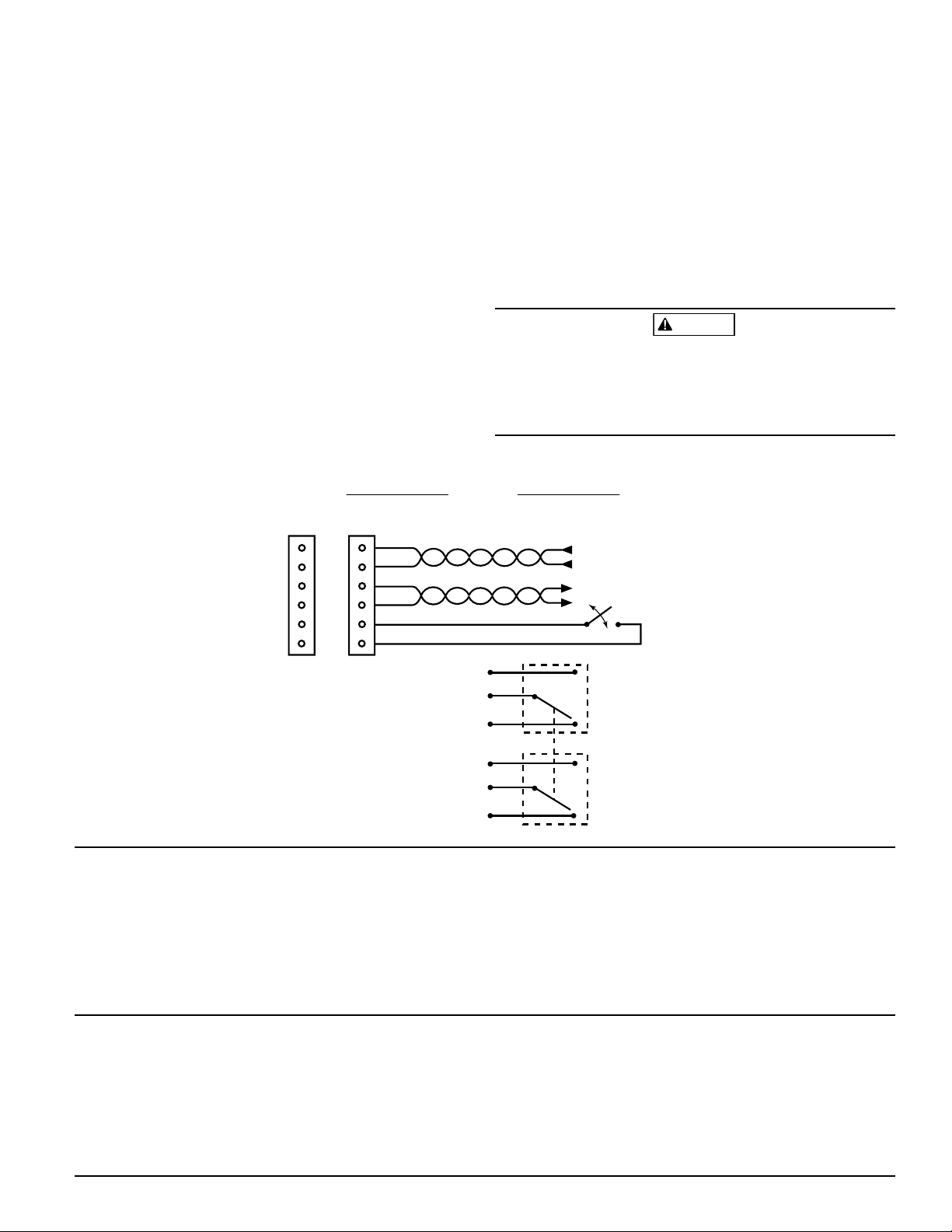
FROM PANEL OR
PREVIOUS PANEL
(–)
(+)
SIGNAL LINE CIRCUIT (SLC)
30 VDC MAX.
TWISTED PAIR RECOMMENDED
SIGNAL LINE CIRCUIT (SLC)
IS SUPERVISED AND
POWER LIMITED
(–)
(+)
(–)
(+)
(–)
(+)
1
2
3
4
TO NEXT DEVICE
5
6
12
11
10
9
8
7
{
RELAY
CONTACTS
NOTE: NORMALLY OPEN
CONNECT MODULES
TO LISTED COMPATIBLE
CONTROL PANELS ONLY
NORMALLY OPEN (T12)
COMMON (T11)
NORMALLY CLOSED (T10)
NORMALLY OPEN (T9)
COMMON (T8)
NORMALLY CLOSED (T7)
RELAY
CONTACT #2
RELAY
CONTACT #1
MODULE DOES NOT SUPERVISE
CONTROLLED CIRCUITS.
TERMINALS 1-6 ARE POWER LIMITED.
TERMINALS 7-12 ARE NON-POWER LIMITED.
WIRING
NOTE: All wiring must conform to applicable local codes, ordinances, and regulations.
1. Install module wiring in accordance with the job drawings
and appropriate wiring diagrams.
NOTE: Separate cable entry openings must be used to maintain
required spacing between power limited and non-power limited wiring. Optional EA-CB may be required to separate power
limited and non power limited wiring in the electrical box.
2. Set the address on the module per job drawings using the IR
configuration tool (model no. EA-CT).
3. Secure module to electrical box (supplied by installer).
AUTO ADDRESSING
Eclipse Series devices are capable of supporting auto addressing,
if the fire alarm control panel is designed to do so. In auto addressing, the control panel, through the use of each device’s onboard isolators, can automatically assign device addresses.
Figure 2: Wiring Diagram
In order to control which devices are addressed first in wiring
configurations with branches, a branch marker can be set at a
particular device. A branch marker is an electronic value from 0 to
255 stored in the device memory. The branch markers are set with
the IR configuration tool, EA-CT.
TERMINAL DEFINITIONS
T1 (+) SLC in/out T7 Normally Closed #1
T2 (–) SLC in/out T8 Common #1
T3 (+) SLC in/out T9 Normally Open #1
T4 (–) SLC in/out T10 Normally Closed #2
T5 (+) Dry Contact Input T11 Common #2
T6 (–) Dry Contact Input T12 Normally Open #2
All relay switch contacts are shipped in the standby state (open)
state, but may have transferred to the activated (closed) state during shipping. To ensure that the switch contacts are in their correct state, modules must be made to communicate with the panel
before connecting circuits controlled by the module.
C0110-02
Three-Year Limited Warranty
Syst em Senso r warrants its encl osed mod ule t o b e f ree from defec ts in ma terials and workman ship u nder nor mal use a nd ser vice for a period of three years
from da te of manufact ure. Sys tem Se nsor makes n o other express warranty for
this modul e. No a gent, representative, dealer, or e mploye e of t he C ompany
has the auth ority to increase or alter the obliga tions or limit ations of this
Warran ty. T he Company’s obligatio n of this Warra nty sh all be li mited to the
repair or replacement of any part of the mod ule wh ich is found to be def ective
in m ateri als or workman ship under no rmal use and serv ice duri ng the th ree
year per iod com menci ng with the date of manufac ture. After pho ning Sys tem
Sensor’s toll f ree nu mber 800 -SENS OR2 (736 -7672) f or a Return Au thorization
number, sen d defect ive units po stage prepaid to: Syste m S ensor, Re turns
This device complies with part 15 of the FCC Rules. Operation is subject to the following two conditions: (1) This device may not cause harmful interference, and (2) this device
must accept any interference received, including interference that may cause undesired operation.
NOTE: This equipment has been tested and found to comply with the limits for a Class B digital device, pursuant to Part 15 of the FCC Rules. These limits are designed to provide reasonable protection against harmful interference in a residential installation. This equipment generates, uses and can radiate radio frequency energy and, if not installed
and used in accordance with the instructions, may cause harmful interference to radio communications. However, there is no guarantee that interference will not occur in a
particular installation. If this equipment does cause harmful interference to radio or television reception, which can be determined by turning the equipment off and on, the user
is encouraged to try to correct the interference by one or more of the following measures:
– Reorient or relocate the receiving antenna.
– Increase the separation between the equipment and receiver.
– Connect the equipment into an outlet on a circuit different from that to which the receiver is connected.
– Consult the dealer or an experienced radio/TV technician for help.
D500-61-00 2 I56-2023-004
©2006 System Sensor
FCC Statement
Departme nt, RA #____ ______, 3825 Ohio Avenue, St. Cha rles, IL 60174 . Plea se
include a n ote d escri bing the m alfunction and suspect ed cause of f ailure. The
Company shall not be ob ligat ed t o repair or repl ace uni ts w hich are found to
be defec tive because of damage, un reasonable use, mo dific ations, or alterations occurring a fter the da te of man ufacture. In no ca se shall the Comp any
be l iable for any cons equenti al or i ncident al dam ages for bre ach of th is or any
other Warran ty, ex pre ssed o r im plied whats oever, eve n if the loss o r da mage
is cause d by the Com pany’s n egligen ce or f ault. S ome s tates d o not a llow the
excl usion or limitation of inc idental or con seque ntial da mages, so the above
limitati on or excl usion may no t apply to yo u. This Warranty gives you spe cific
legal rights, an d yo u may al so have oth er rig hts wh ich vary from sta te to stat e.
 Loading...