

Page 1
INSTALLATION AND MAINTENANCE INSTRUCTIONS
3
I56-3741-001R
EBR Plug-in
Relay Detector Base
SPECIFICATIONS
Base Diameter: 6.85 in (17.4 cm)
Base Height (less sensor): 1.61 in (4.1 cm)
Operating Temperature Range: Refer to applicable sensor Operating Temperature Range using the Base/Sensor Cross Reference Chart at systemsensor.com
Operating Humidity Range: 10% to 93% Relative Humidity (Non-condensing)
Electrical Ratings
Operating Voltage: 15 to 32 VDC
Standby Current: 170 µA
Relay Characteristics
Coil: 2 coil latching
Contact Type: Form C
Contact Relay Ratings
CURRENT RATING MAXIMUM VOLTAGE LOAD DESCRIPTION APPLICATION
2 A 25 VAC PF = 0.35 Non-coded
3 A 30 VDC Resistive Non-coded
2 A 30 VDC Resistive Coded
0.46 A 30 VDC (L/R = 20ms) Non-coded
0.7 A 70.7 VAC PF = 0.35 Non-coded
0.9 A 125 VDC Resistive Non-coded
0.5 A 125 VAC Resistive Non-coded
0.3 A 125 VAC PF = 0.35 Non-coded
3825 Ohio Avenue, St. Charles, Illinois 60174
1-800-SENSOR2, FAX: 630-377-6495
www.systemsensor.com
Set Time: 20 msec
Reset Time: 250 msec
BEFORE INSTALLING
Please read the System Smoke Detector Applications Guide, which provides
detailed information on detector spacing, placement, zoning, wiring, and special applications. Copies of this application guide are available from System
Sensor. NFPA 72 guidelines should be observed.
NOTICE: This manual should be left with the owner/user of this equipment.
IMPORTANT: The detector used with this base must be tested and maintained
regularly following NFPA 72 requirements. The detector should be cleaned at
least once a year.
GENERAL DESCRIPTION
The relay base is intended for use with intelligent systems. Refer to the panel
manual for maximum allowable number of units per loop.
Form C latching relay contacts are included for the control of an auxiliary
function.
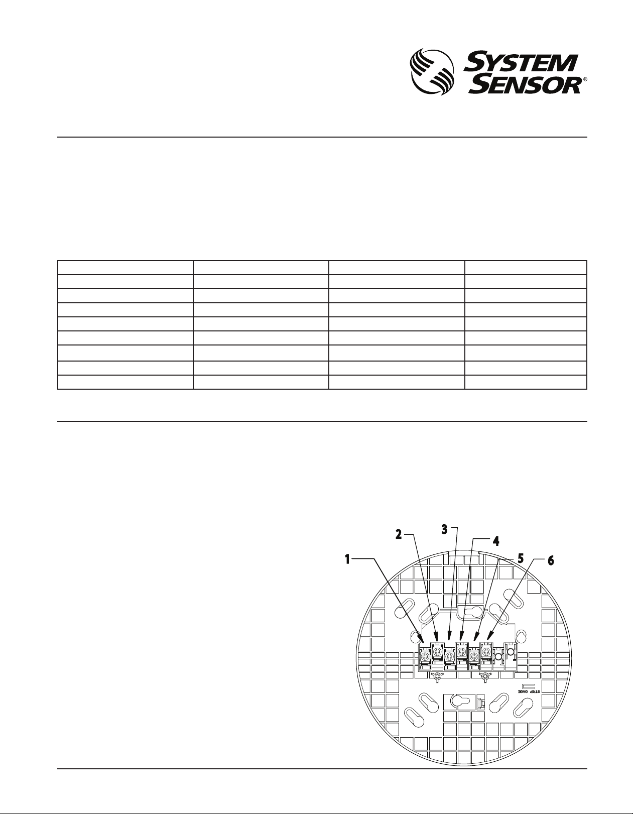
BASE TERMINALS
NO. FUNCTION
1. Normal Close
2. Common
3. Normal Open
4. Comm. (–)
5. Comm. (+) In/Out
6. Comm. (+) Out/In
FIGURE 1. TERMINAL LAYOUT:
2
1
4
5
6
CO471-04
SS-450-006 1 I56-3741-001R
Page 2
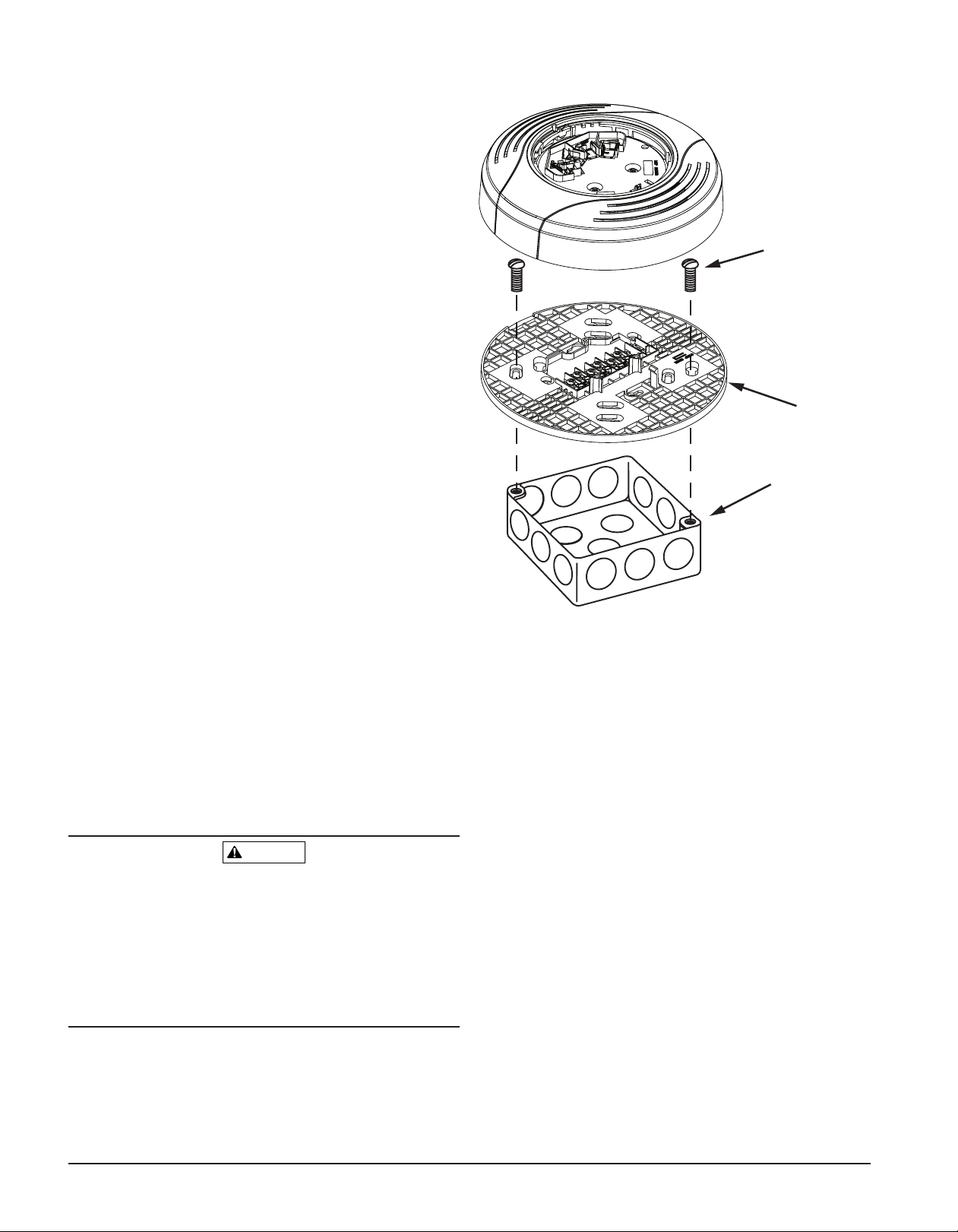
MOUNTING
WARNING
Mount the mounting plate directly to an electrical box. The plate will mount
directly to 4-inch square, 4-inch octagon, 3 ½-inch octagon, single gang and
double gang junction boxes.
1. Connect field wiring to terminals, as shown in Figure 3.
2. Attach the mounting plate to the junction box as shown in Figure 2.
3. To mount the base, hook the tab on the base to the groove on the
mounting plate.
4. Then, swing the base into position to engage the pins on the product
with the terminals on the mounting plate.
5. Secure the base by tightening the mounting screws.
6. Install a compatible smoke detector as described in the installation
manual for the detector.
INSTALLATION AND WIRING GUIDELINES
All wiring must be installed in compliance with all applicable local codes
and any special requirements of the local authority having jurisdiction. Proper
wire gauges should be used. The conductors used to connect smoke detectors
to control panels and accessory devices should be color-coded to reduce the
likelihood of wiring errors. Improper connections can prevent a system from
responding properly in the event of a fire.
For signal wiring (the wiring between interconnected detectors), it is recommended that the wire be no smaller than 18 AWG (0.823 square mm). Wire
sizes up to 12 AWG (3.31 square mm) may be used with the base. The base
will be shipped with the screw terminals set for 14 AWG wiring. If 12 AWG
wire is used, back out the screws to allow the wire to fit beneath the clamping plates.
Make electrical connections by stripping about 3/8 inch (10 mm) of insulation
from the end of the wire (use strip gauge molded in base). Then slide the wire
under the clamping plate and tighten the clamping plate screw. Do not loop
the wire under the clamping plate. (See Figure 4)
Wire the normally open (NO) line to terminal 3 (see Figure 3). Insert the normally closed (NC) line of the relay to terminal 1 and the relay common line
to terminal 2. Wire the communication lines in (–) and out (–)to terminal 4.
Insert the communication line in (+) and out (+) to terminal 5.
Check the zone wiring of all bases in the system before installing the detectors. This includes checking the wiring for continuity, correct polarity,
ground fault testing and performing a dielectric test.
The base includes an area for recording the zone, address, and type of detector being installed. This information is useful for setting the detector head
address and for verification of the detector type required for that location.
Once all detector bases have been wired and mounted, and the loop wiring
has been checked, the detector heads may be installed in the bases.
Alarm system control panels have specifications for allowable loop resistance.
Consult the control panel specifications for the total loop resistance allowed
before wiring the detector loops.
FIGURE 2. MOUNTING THE BASE TO AN ELECTRICAL BOX:
SCREWS
(NOT SUPPLIED)
BOX
(NOT SUPPLIED)
MOUNTING
PLATE
C0148-03
The base uses a latching relay that can change states if it is subjected to mechanical shocks or jarring. As a result, even though relay contacts are in the
open state when the base is shipped from the factory, the contacts may have
closed during shipment.
Connecting an auxiliary control circuit to closed relay contacts can cause an
unexpected, and possibly dangerous, activation of that circuit. Therefore, do
NOT connect an auxiliary control circuit to the relay contacts (terminals 1, 2,
and 3) before ensuring that the relay contacts are in their open state. Ensure
that the contacts are open by applying power to the bases WITHOUT the detector heads installed.
SS-450-006 2 I56-3741-001R
Page 3
CLASS A OPTIONAL WIRING
OTHER INTELLIGENT
FIGURE 3. WIRING DIAGRAM:
PLASTIC LEVER
BREAK TAB AT
DOTTED LINE BY
TWISTING TOWARD
CENTER OF BASE.
USE SMALL-BLADED
SCREWDRIVER TO
PUSH PLASTIC LEVER
IN DIRECTION OF
ARROW.
SLOT
THIS NOT THIS
Comm.(+)
Comm.(–)
LISTED COMPATIBLE CONTROL PANEL
SLC (+)
SLC (–)
DEVICES
(+)
(–)
FIGURE 4:
TAMPER-RESIST FEATURE
NOTE: Do not use the tamper-resist feature if the removal tool will be used.
The detector base includes a tamper-resist feature that prevents removal of
the detector from the base without using a small screwdriver or similar tool.
To activate this feature, use needle-nose pliers to break the tab on the detector
base as shown in Figure 5A. Then, install the detector.
To remove the detector from the base once the tamper-resist feature has been
activated, insert a small-bladed screwdriver into the slot from the top and
press down on the lever (see Figure 5B). This allows the detector to be rotated
counterclockwise for removal.
The tamper-resist feature can be defeated by breaking and removing the plastic
lever from the base. However, this prevents the feature from being used again.
C0737-00
2 RELAY COMMON
1 NORMALLY CLOSED
3 NORMALLY OPEN
FIGURE 5A. ACTIVATING THE TAMPER-RESIST FEATURE:
FIGURE 5B. REMOVING THE DETECTOR HEAD FROM THE BASE:
SLOT
C0890-03
C0144-00
C1082-00
SS-450-006 3 I56-3741-001R
Page 4

Please refer to insert for the Limitations of Fire Alarm Systems
THREE-YEAR LIMITED WARRANTY
System Sensor warrants its enclosed smoke detector base to be free from defects in materials and workmanship under normal use and service for a period of three years from
date of manufacture. System Sensor makes no other express warranty for this smoke
detector base. No agent, representative, dealer, or employee of the Company has the authority to increase or alter the obligations or limitations of this Warranty. The Company’s
obligation of this Warranty shall be limited to the replacement of any part of the smoke
detector base which is found to be defective in materials or workmanship under normal
use and service during the three year period commencing with the date of manufacture.
After phoning System Sensor’s toll free number 800-SENSOR2 (736-7672) for a Return
Authorization number, send defective units postage prepaid to: System Sensor, Returns
SS-450-006 4 I56-3741-001R
©2011 System Sensor
Department, RA #__________, 3825 Ohio Avenue, St. Charles, IL 60174. Please include
a note describing the malfunction and suspected cause of failure. The Company shall
not be obligated to replace units which are found to be defective because of damage,
unreasonable use, modifications, or alterations occurring after the date of manufacture.
In no case shall the Company be liable for any consequential or incidental damages for
breach of this or any other Warranty, expressed or implied whatsoever, even if the loss
or damage is caused by the Company’s negligence or fault. Some states do not allow the
exclusion or limitation of incidental or consequential damages, so the above limitation
or exclusion may not apply to you. This Warranty gives you specific legal rights, and you
may also have other rights which vary from state to state.
 Loading...