

Page 1
INSTALLATION AND MAINTENANCE INSTRUCTIONS
EA-CT Configuration Tool
SPECIFICATIONS
Dimensions: 1.3˝H×2.2˝W×7.7˝L
(33mm H×56mm W×196mm L)
Communication Range: 30 ft. (9.1 m)
24 ft (7.3m) with dust cover on device
Battery Life (2 AA, batteries not included): 168 hrs (typical usage)
Storage Temperature Range: –4ºF to 140ºF (–20ºC to 60ºC)
Operating Temperature Range: 32ºF to 122ºF (0ºC to 50ºC)
I56-2245-005
3825 Ohio Avenue, St. Charles, Illinois 60174
1-800-SENSOR2, FAX: 630-377-6495
www.systemsensor.com
PRODUCT DESCRIPTION
The EA-CT is a hand-held remote control that is designed to communicate
with Eclipse devices via infrared signals. The remote control will give the
user the ability to communicate with the panel and other devices through any
selected device on the loop. The EA-CT can read device information such as
type, loop, address and sensitivity along with write loop, address, branch , serial number and service date, and initiate walk test and device test. The EA-CT
features a 16-character liquid crystal display and a 17-button keypad.
GLOSSARY
Address: Loop and address are the two components of a device’s identifier
in an Eclipse system. Addresses 1 to 254 are valid for detectors and modules.
Branch: For loops that use t-taps or star-taps, a branch number can be specified on each device after the tap to indicate which device will be programmed
first in a system with auto-addressing. The branch number can be from 1 to
255.
Deselect: If a user decides not to communicate to a device that has been selected, it may be deselected and another device chosen instead.
Loop: Loop and address are the two components of a device’s identifier in an
Eclipse system. With Eclipse, multiple loops may reside on the same pair of
wires. Loops can be numbered 1 to 254.
Master Key: If a user misplaces their PIN number, the EA-CT can generate a
code or master key that will allow technical support to provide a temporary
PIN number for access.
NO COMM.RETRY?: This message will appear on the configuration tool
screen if the message was not transmitted properly to the receiving device.
Repeat the steps to complete the desired action.
PIN number: The EA-CT is equipped with a personal identification number
that, when enabled, prevents unauthorized use of the device.
Select: Since the EA-CT can conceivably have more than one detector
or module within its field of view, only one device can be chosen or
“selected” from the group. The select key is used to choose the device
to which the EA-CT will communicate. Pressing the SELECT key more than
once will alternately select each device within the EA-CT range. A selected
device is ready to receive communications from the EA-CT.
Target: The target is the address of the device that you would like to communicate with using the EA-CT. The target is not necessarily the device that is
selected or a device in the line of sight.
GENERAL INSTRUCTION
Press the PWR button on the EA-CT. For first time users or devices without
a PIN number, the main menu will be displayed. To be able to set your PIN
number, refer to the PIN enable/disable (7.1) section of this manual. The
main menu consists of seven choices for the user. You can select each choice
by pressing the up or down keys to highlight your selection and pressing enter
or by pressing the number of the selected item.
NOTE: EA-CT automatically shuts down after 200 seconds of non-use.
Before communication is enabled, the device must be “selected” by the EACT. To select a device, aim the EA-CT at the device and press the SELECT key.
In situations where there is more than one device in close proximity, the de-
sired device may not be initially selected. Simply press the SELECT key again
and that device will be deselected and another device within the EA-CT field
of view will be selected. To deselect a device, aim the EA-CT at the device and
press the DESELECT key. A device can be selected or deselected at any time.
When a device is selected by the EA-CT, the LED on the device will change
to a blinking green pattern. This will help the user ensure the correct Eclipse
device is selected. The only exception is the mini monitor module. This unit’s
LED will temporarily turn off because it does not have a bi-color LED.
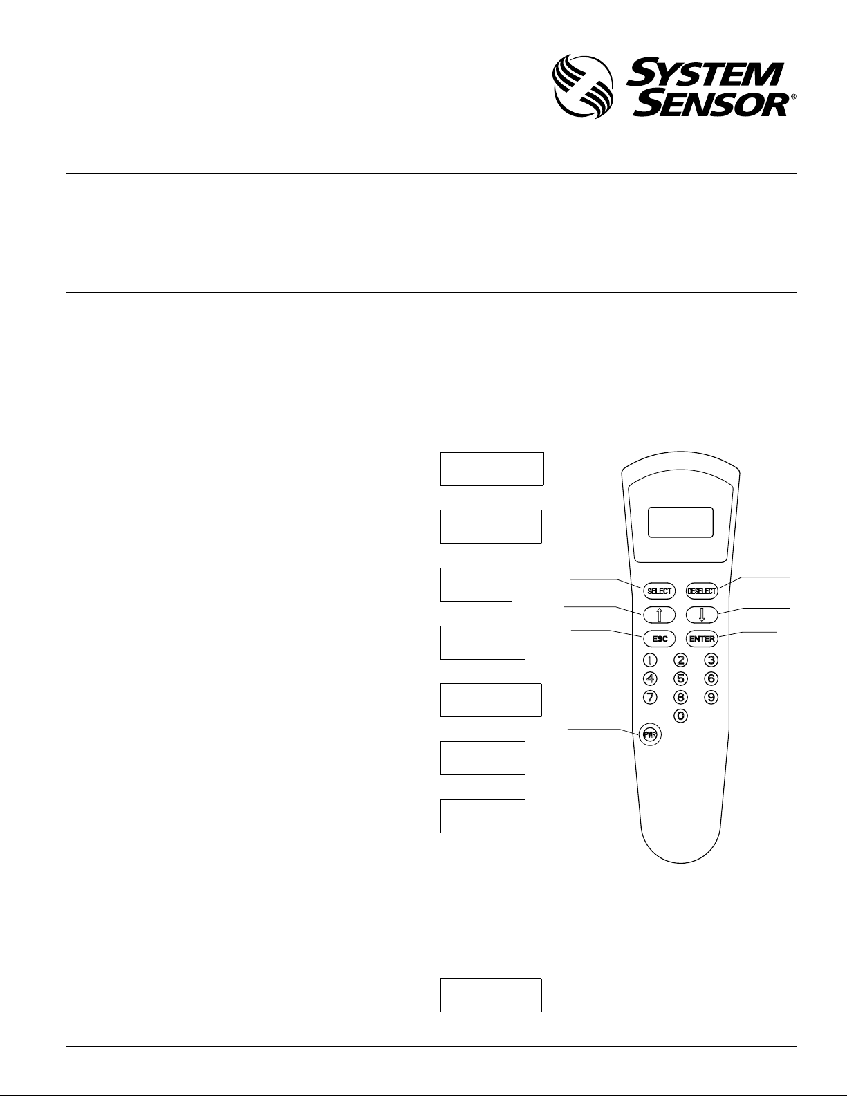
MAIN MENU
1. WRITE
LOOP/ADR
Set Address Screen
2. READ
LOOP/ADDR
Loop and Address Read Screens
3. READ
DEVICE
Acquire Screen
4. WRITE
SELECT KEY
SCROLL UP KEY
ESCAPE KEY
DESELECT KEY
SCROLL DOWN
KEY
ENTER KEY
SERVICE
Set Service Date Screen
5. TEST
MODES
Test Mode Options
POWER BUTTON
6. CHOOSE
TARGET
Choose Target Loop/Address
7. TOOL
OPTIONS
Tool Options Menu
NOTE: There must be a clear line of sight between the EA-CT and the device
it is communicating with.
1. WRITE LOOP/ADDRESS
This option is for assigning an Eclipse device to a certain loop and address.
When this option is chosen by pressing ENTER, the following screen is displayed:
LOOP?000
ADDR?000
D800-20-00 1 I56-2245-005
Page 2

The user may then enter the specific address and loop designation desired for
that device. The maximum address and loop numbers that can be used are
254. After an address is entered, point the EA-CT to the device whose address
you wish to set. Press the SELECT key to select that device. When the ENTER
key is pressed, the device will start a communication. If there is a problem
with the communication a trouble screen will be displayed:
NO COMM.
RETRY?
To retry, press the ENTER key again and the EA-CT will attempt to re-connect
to the device. If the address is accepted, the following screen will be displayed:
OK NEW
ADDR. SET
At this point if the user wishes to increase the address number, the up arrow should
be pressed, and the following screen will appear with the address incremented:
LOOP?000
ADDR?000
If at this point the user selects another unit using the SELECT button, by
pressing ENTER the incremented address and the same loop will be recorded
on the new unit.
The same functionality is available by using the down arrow.
2. READ LOOP/ADDR
Pressing ENTER at this menu option will give the user the ability to read a
selected Eclipse device to see what its current address and loop designation
is. When this choice is made, the screen will prompt the user to point to the
device that is to be read. Point to the device that you want to read and press
the ENTER key. If the communication is successful, the screen will display
something similar to the following example:
LOOP: 147
ADDR: 123
If there is a problem with the communication, trouble screen is received:
NO COMM.
RETRY?
To retry, press the enter key again and the EA-CT will attempt to communicate
again to the device.
3. READ DEVICE
This menu option will indicate, for a selected device, its type, address, loop,
and branch marker. When ENTER is pressed on this option, the first screen
that comes up, is similar to:
LOOP: 147
ADDR: 123
If that is not the correct loop or address, the user can press ESC to go back to
the Address Set Screen to make the change. If that is the correct setting and
the selected device is a device with isolators, the down arrow key is pressed to
show the branch setting similar to the example:
BRANCH#
IS:XXX
If that is not the correct branch number, the user can go to the Branch Setting
screen by pressing enter again to make the appropriate changes.
SET BRANCH #
To set a branch marker on a selected device, press the enter key on this option, and after the set new branch screen is displayed the following screen
will come up:
BRANCH #
?XXX
Enter the branch number that is desired. Point the EA-CT at the device that
is to receive the branch marker. Press enter and, after a moment, the EA-CT
will display:
To display the new branch number press ESC twice
BRANCH #
IS: XXX
NOTE: If the selected device does not contain isolators the following serial
number screen will appear immediately following the loop and address view.
SNo. 0XXX
XXXXXXXX
The next screen that comes up will depend on the device type.
If the device is a heat detector the following display will appear:
HEAT
DETECTOR
If the device is a heat detector, the user can press the down key again to find
out whether the device is set at a rate-of-rise or a fixed temperature setting.
If the detector is configured to be a rate-of-rise detector, the following screen
will appear:
ALARMS:
ROFRISE
If the detector is configured at a fixed heat temperature setting and is on the
US menu setting, the following screen will appear:
S1:XXX ºF
S2:XXX ºF
If the detector is configured at a fixed heat temperature setting and is on the
Non-US menu setting, the following screen will appear:
S1:XXX ºC
S2:XXX ºC
If the device is a photo-heat detector, the following screen will appear:
Photo-HT
Detector
If the down arrow is pressed again, a screen similar to this one will show whether
the device is configured to Acclimate.
AHIS: 0.5
ALOS: 4.0
This screen shows the sensitivity level of the photo-heat detector. The AHIS
is the upper limit of the Acclimate sensitivity range in percent per foot. The
ALOS indicates the lower limit of the Acclimate sensitivity range in percent
per foot. Detector sensitivity cannot be changed using the EA-CT. Please refer
to the control panel installation manual to change the levels of sensitivity on
the detector. If the down arrow is pressed again a screen similar to this one
will appear:
SENS. FE
LEVEL: 2.4
The “FE” appears only if the detector has a flame enhancement feature and
that feature is currently enabled. The second line indicates what the detector’s
exact sensitivity is at that moment.
If the device is not configured to Acclimate the following screen similar to this
one will appear:
S1:XXX
S2:XXX
This shows the sensitivity level corresponding to the sensitivity broadcasts.
Pressing the down arrow again will show how dirty the detector is. This is
indicated as the percentage of drift compensation limit used. Please refer to
the control panel installation manual for the percentage that requires cleaning.
BRANCH
NUM. set
D800-20-00 2 I56-2245-005
Page 3

% DIRTY
0000
If the device is a photo-duct detector, the following screen will appear:
PHO-DUCT
DETECTOR
If the down arrow is pressed again, a screen similar to this one will appear:
S2: X.X%
XXMIC
This shows the sensitivity level corresponding to the sensitivity broadcasts.
Pressing the down arrow again will show how dirty the detector is. This is
indicated as the percentage of drift compensation limit used. Please refer to
the control panel installation manual for the percentage that requires cleaning.
If the device is a control module, the following screen will appear:
S1:XXX
S2:XXX
This screen shows the levels of sensitivity for the selected device. Pressing the
down arrow again will show how dirty the detector is. This is indicated as the
percentage of drift compensation limit used. Please refer to the control panel
installation manual for the percentage that requires cleaning.
If the device is a photo detector, the following screen will appear:
PhotoDCT
Detector
If the down arrow is pressed again, a screen similar to this one will show up if
the device is configured to Acclimate.
AHIS: 0.5
ALOS: 4.0
This screen shows the Acclimate sensitivity range of the photo detector. The
AHIS is the upper limit of the sensitivity range in percent per foot. The ALOS
indicates the lower limit of the sensitivity range in percent per foot. Detector
sensitivity cannot be changed using the EA-CT. Please refer to the control
panel installation manual to change the levels of sensitivity on the detector.
If the down arrow is pressed again a screen similar to this one will appear:
SENS
LEVEL: 2.4
If the device is not configured to Acclimate the following screen similar to this
one will appear:
S1:XXX
S2:XXX
This shows the sensitivity level corresponding to the sensitivity broadcasts.
Pressing the down arrow again will show the how dirty the detector is. This
is indicated as the percentage of drift compensation limit used. Please refer to
the control panel installation manual for the percentage that requires cleaning.
If the device is an Ion detector, the following screen will appear:
ION SE
DETECTOR
If the down arrow is pressed again, a screen simliar to this one will show up if
the device is configured to Acclimate:
AHIS.X.X%
XXMIC
If the down arrow is pressed again, a screen simliar to this one will show up:
ALOS X.X%
XXMIC
If the down arrow is pressed again, a screen similar to this one will appear:
SENS X.X%
XXMIC
If the device is not configured to Acclimate a screen similar to this one will appear:
S1: X.X%
XXMIC
If the down arrow is pressed again, a screen similar to this one will appear:
Optionally “SE” will appear if smoldering is enabled
Reporting the Acclimate Hi sensitivity
Reporting the Acclimate Low sensitivity
Showing the current detector’s sensitivity
CONTROL
MODULE
If the device is a relay module, the following screen will appear:
RELAY
MODULE
If the device is a monitor module, the following screen will appear:
MONITOR
MODULE
If the device is mini module, the following screen will appear:
MINI
MODULE
If the device is a pull station, the following screen will appear:
PULL
STATION
If the device is conventional zone module, the following screen will appear:
CONV ZON
MODULE
If the device is dual monitor module, the following screen will appear:
DUAL MON
MODULE
When the down arrow is pressed again on all ECLIPSE devices the screen will
show the date when each device was last serviced (if the service data was
set during the last service). If the Menu Settings are set to US format the date
format will be MM/DD/YY. If the settings are Non-US setting the date will be
displayed as DD/MM/YY.
SERVICED
07/16/12
When the down arrow is pressed again on all devices, the display will show the
date the device was manufactured in weeks of the year followed by the year.
MANUF.:
WK: 02,11
4. WRITE SERVICE
This setting allows a service technician to record when the selected Eclipse device has been serviced. When this choice is made, the EA-CT will request the
user to point to the selected device, and if the communication is successful, a
screen similar to the following is displayed:
SERVICED:
10/10/95
NOTE: The service date is automatically entered as the current date and cannot be changed to a different day.
5. TEST MODES
5.1 TEST ALARM
This option will cause a device to self-test. Point to the selected device that requires testing and press enter. When the communication is complete, a screen
similar to this will be displayed:
OK ALARM TEST SET
D800-20-00 3 I56-2245-005
Page 4

5.2 EXIT ALARM
Pressing enter on this choice will end the test on the given device. Point to the
selected device whose alarm is to be cleared. If the communication is successful and the test is ended the following screen will appear:
OK ALARM
TEST CLR
6. CHOOSE TARGET
This option is for communicating with devices that cannot be seen in the line
of sight of the EA-CT such as those mounted above the ceiling or below the
floor. Begin by selecting a device within the line of sight. The out of sight
device will be able to communicate through that SELECTED device. When this
option is selected, the following screen is displayed:
LOOP?000
ADDR?000
Enter the specific address of the device with which communication is desired
and press the enter key. The user will then proceed to the main menu and
perform read/write options.
7. TOOL OPTIONS
The user can scroll through the different choices of the options menu by using
the arrow keys.
7.1 PIN
EN./DIS.
This option enables or disables the PIN number function. When ENTER is
pressed the following screen appears:
ENABLE
*DISABLE
The asterisk points to the setting currently selected. Use either of the arrow
keys to move the asterisk to the desired option and press ENTER. If the asterisk moves to the Enable line, then the PIN number is enabled.
NOTE: If the wrong PIN number is entered upon power-up, the EA-CT will
automatically shut off.
7.2 PIN
CHANGE
This option is used to enter or change the PIN number. When this is selected
the following screen comes up:
MASTER KEY PROTECTION
The EA-CT also provides a security feature for the user in the event that a PIN
number is entered and then forgotten, preventing access to the device. When
the PIN screen is displayed upon power-up, press the ESC key on the keypad.
A screen similar to this one will be displayed:
MASTER
KEY: 5698
(Note: 5698 is just an example)
Make note of the number that is displayed and contact System Sensor technical support (800-sensor2). Tell the representative the Master Key number on
the display and they will be able to provide access to the device via a temporary PIN number.
NOTE: The Master Key number on the display is different every time, so the
user must always look at the number before calling System Sensor.
7.3 LCD
INTENS.
This option adjusts the viewing of the screen. Select this option and use the arrows to change the intensity of LCD screen.
7.4 CHK.
BATTERY
This option checks the status of the battery. The more shadow boxes the
screen shows, the more life a battery has. When the screen is showing only
one asterisk, the battery should be replaced. A low battery message is displayed once the battery is too low to provide enough power to operate the
EA-CT.
7.5 MENU
MODES
This option allows changes to the date code of the EA-CT to either month-dayyear format or the day-month-year format. When this option is selected the
following screen will be displayed:
SET MENU
STYLES: US
EU
Use the arrow keys to select the requested choice and press the enter key. The
date codes will automatically be displayed in the requested format.
?PIN#
XXXX
The user types the desired PIN number and presses the enter key. The new
PIN number is activated.
NOTE: Any PIN number entered here supersedes any previous PIN number
that was being used.
System Sensor warrants its enclosed product to be free from defects in materials and
workmanship under normal use and service for a period of three years from date of
manufacture. System Sensor makes no other express warranty for the enclosed product.
No agent, representative, dealer, or employee of the Company has the authority to in
crease or alter the obligations or limitations of this Warranty. The Company’s obligation
of this Warranty shall be limited to the replacement of any part of the product which
is found to be defective in materials or workmanship under normal use and service
during the three year period commencing with the date of manufacture. After phoning
System Sensor’s toll free number 800-SENSOR2 (736-7672) for a Return Authorization
number, send defective units postage prepaid to: System Sensor, Returns Department, RA
This device complies with part 15 of the FCC Rules. Operation is subject to the following two conditions: (1) This device may not cause harmful interference, and (2) this device must
accept any interference received, including interference that may cause undesired operation.
NOTE: This equipment has been tested and found to comply with the limits for a Class B digital device, pursuant to Part 15 of the FCC Rules. These limits are designed to provide reason
able protection against harmful interference in a residential installation. This equipment generates, uses and can radiate radio frequency energy and, if not installed and used in
accordance with the instructions, may cause harmful interference to radio communications. However, there is no guarantee that interference will not occur in a particular installa
tion. If this equipment does cause harmful interference to radio or television reception, which can be determined by turning the equipment off and on, the user is encouraged to
try to correct the interference by one or more of the following measures:
– Reorient or relocate the receiving antenna.
– Increase the separation between the equipment and receiver.
– Connect the equipment into an outlet on a circuit different from that to which the receiver is connected.
– Consult the dealer or an experienced radio/TV technician for help.
THREE-YEAR LIMITED WARRANTY
FCC STATEMENT
#__________, 3825 Ohio Avenue, St. Charles, IL 60174. Please include a note describing
the malfunction and suspected cause of failure. The Company shall not be obligated to
replace units which are found to be defective because of damage, unreasonable use,
-
modifications, or alterations occurring after the date of manufacture. In no case shall the
Company be liable for any consequential or incidental damages for breach of this or any
other Warranty, expressed or implied whatsoever, even if the loss or damage is caused by
the Company’s negligence or fault. Some states do not allow the exclusion or limitation of
incidental or consequential damages, so the above limitation or exclusion may not apply
to you. This Warranty gives you specific legal rights, and you may also have other rights
which vary from state to state.
D800-20-00 4 I56-2245-005
©2012 System Sensor
-
-
 Loading...