

Page 1

INSTALLATION AND MAINTENANCE INSTRUCTIONS
DH500 Intelligent Air Duct Smoke
Detector Housing
Specifications
Length: 14.5 inches (36.7 cm)
Width: 5 inches (12.7 cm)
Depth: 3.5 inches (8.9 cm)
Weight: 2.8 lbs. (1.1 kg)
Operating Temperature Range: 32° to 120°F (0° to 49°C)
Operating Humidity Range: 10% to 93% Relative Humidity
Duct Air Velocity: 500 – 4000 ft./min. (91.4 – 1219.2 m/min.)
Electrical Ratings for DH500
Voltage Range: 14.5 – 32 VDC Peak
Standby Current (nominal): 150uA at 24 VDC
Power-Up Surge at Max.
Rated Voltage: 1.5mA-sec.
LED current (nominal): 6mA at 24 VDC
Before Installing
Please thoroughly read System Sensor’s Guide for Proper
Use of Smoke Detectors in Duct Applications (I56-473-XX),
which provides detailed information on detector spacing, placement, zoning, wiring, and special applications.
Copies of this manual are available from System Sensor.
NFPA Standards 72 and 90A should also be referenced for
detailed information.
NOTICE: This manual should be left with the owner/user
of this equipment.
IMPORTANT: This detector must be tested and maintained
regularly following NFPA 72 requirements. The detector
should be cleaned at least once a year.
General Description
An HVAC system supplies conditioned air to virtually every
area of a building. Smoke introduced into this air duct system will be distributed to the entire building. Smoke detectors designed for use in air duct systems are used to sense
the presence of smoke in the duct.
The DH500 Air Duct Detector Housings are used with
System Sensor’s intelligent model 1551 ionization detector
head and model 2551 photoelectronic detector head. These
two principal smoke detection methods are combined with
an efficient housing design that samples air passing through
a duct and allows early detection of a developing hazardous
condition. When sufficient smoke is sensed, an alarm signal
is initiated at the fire control panel monitoring the detector,
and appropriate action can be taken to shut off fans and
blowers, change over air handling systems, etc. This can
prevent the distribution or isolation of toxic smoke and fire
gases throughout the areas served by the duct system.
Two LEDs on each detector latch ON to provide a local
alarm indication. There is also a remote alarm output
for use with auxiliary devices. The DH500 has remote
test capability with the RTS451/RTS451KEY Remote Test
Station.
Contents of the Duct Detector Housing Kit
The DH500 consists of the following items: (See Figure 1.)
See Note 1 on Page 2 for inlet sampling tube and detector
supply information.
1. Complete housing base and cover assembly.
2. Two #10 sheet metal mounting screws.
3. Two sampling tube filters.
4. One test magnet.
5. Drilling template.
6. Two 5/16-inch O-rings.
7. Two rubber tube bushings seals.
8. Four #6 self-tapping mounting screws for the sampling
tube.
9. One filter adapter.
10. One inlet tube end plug.
11. Four #6x7/10 cover mounting screws.
12. Two #10 speed nuts.
13. One test coil and parts bag.
3825 Ohio Avenue, St. Charles, Illinois 60174
1-800-SENSOR2, FAX: 630-377-6495
www.systemsensor.com
D500-08-00 1 I56-512-07R
Page 2
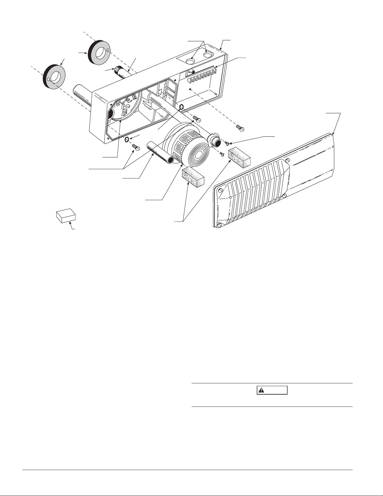
SAMPLING TUBE
FILTERS
CONDUIT HOLES
DUCT DETECTOR
HOUSING
TERMINAL STRIP
DUCT DETECTOR
COVER
SAMPLING TUBE
MOUNTING
SCREWS
DETECTOR HEAD
(SUPPLIED SEPARATELY)
EXHAUST
FILTER ADAPTER
DETECTOR BASE
INLET SAMPLING TUBE
(SUPPLIED SEPARATELY)
O-RINGS
FOAM
GASKETS
HOUSING
MOUNTING SCREWS
TEST MAGNET
TUBE
END
PLUG
Figure 1:
CAUTION
NOTE: The inlet sampling tube must be ordered sepa-
rately. It must be the correct length for the width
of the duct where it will be installed. See Table 1 to
determine the inlet tube required for different duct
widths. Smoke detector heads (1551, ionization;
2551, photoelectronic) must be ordered separately.
Installation Sequence Page
Step 1. Verify duct air flow direction and velocity 2
Step 2. Drill the mounting holes 3
Step 3. Secure the housing base to the duct 3
Step 4. Install the inlet sampling tube 3
Step 5. Field wiring 5
Step 6. Install the filters and check pressure differential 5
Step 7. Perform detector check 7
Step 8. Install the cover 8
Step 9. Perform the final system check (Testing) 8
Step 1. Verify Duct Air Flow Direction and Velocity
The DH500 is designed to be used in air handling systems
having air velocities of 500 to 4000 feet per minute. Be sure
to check engineering specifications to ensure that the air
velocity in the duct falls within these parameters. If necessary, an Alnor Model 6000-P velocity meter, Dwyer 460 differential pressure gauge, or their equivalent, may be used
to check the air velocity in the duct.
H0297-00
Step 2. Drill the Mounting Holes
Remove the paper backing from the top and bottom of the
template. Affix the template to the air duct at the desired
mounting location. Make sure the template lies flat and
smooth on the air duct. Center punch hole targets and
remove the template. Drill the holes as indicated on the
template. Slide the two speed nuts over the two small holes
(Hole A) next to the sampling tube bushing holes (Hole B)
previously drilled in the duct. (See Figure 2.)
Step 3. Mount Duct Housing
Remove the duct housing cover. Slide the foam gaskets over
the tube bushings as shown in Figure 2B. Make sure the
two small holes in the gaskets line up with the two base
mounting holes. Put one 5/16-inch O-ring over each of the
two #10 sheet metal screws. Use the two sheet metal screws
to secure the duct housing to the duct.
Do not overtighten the screws.
D500-08-00 2 I56-512-07R
Page 3
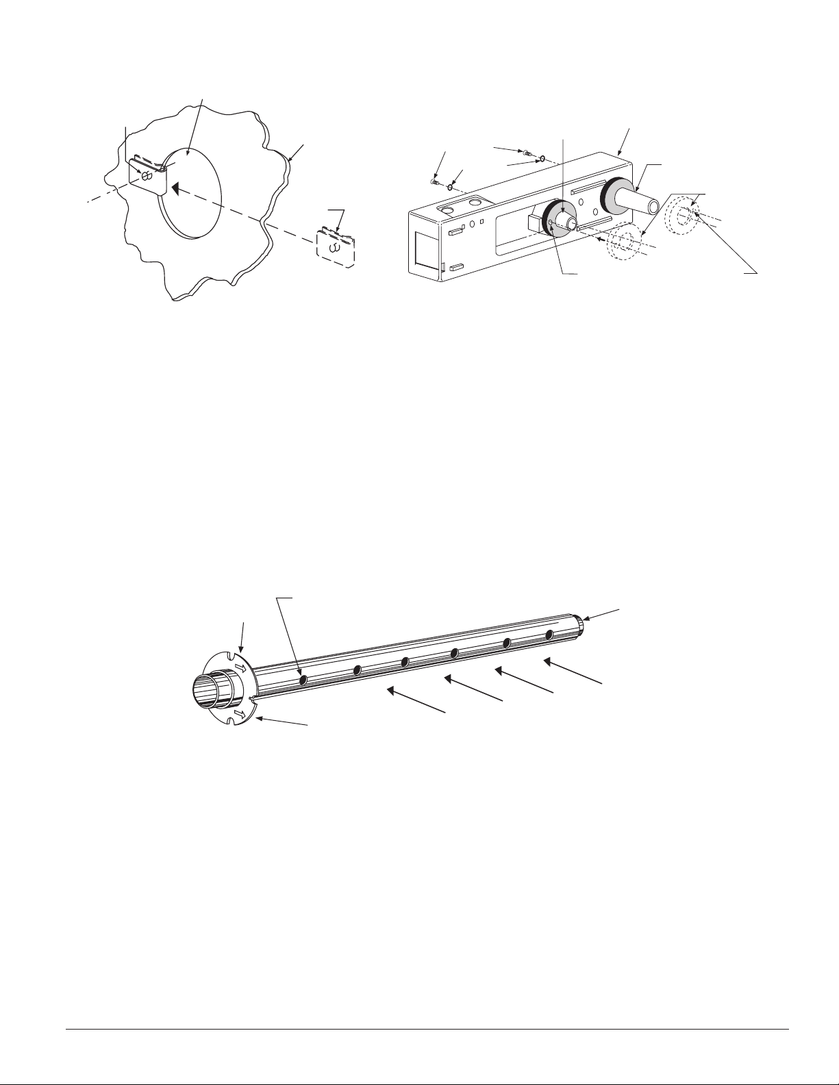
HOLE B
HOLE A
DUCT
WALL
SPEED
NUT
SCREW HOLES FOR AT TACHING
DETECTOR HOUSING TO DUCT
FOAM GASKETS
EXHAUST TUBE
(EXTENSION BUSHING)
DUCT DETECTOR
HOUSING
O-RINGS
MOUNTING
SCREWS
INLET SAMPLING
TUBE BUSHING
Figure 2A. Speed nut mounting location:
INLE
T
TUBE
END
PLUG
AIR HOLES
ARROWS
MUST FACE
INTO AIR FLOW
AIR FLOW DIRECTION
FLANGE
H0116-00 H0238-00
Table 1. Sampling (Inlet) Tubes
Tube Outside Duct Width
ST-1.5 1 to 2 ft. (0.3 to 0.6 m)
ST-3 2 to 4 ft. (0.6 to 1.2 m)
ST-5 4 to 8 ft. (1.2 to 2.4 m)
ST-10 8 to 12 ft. (2.4 to 3.7 m)
Step 4. Install the Inlet Tube
The inlet tube (shown in Figure 3) is identified by a series
Figure 3. Air duct detector inlet sampling tube:
Figure 2B. Installation of foam gaskets over sampling tube bushings:
of air inlet holes on the tube. This tube must be purchased
separately. Order the correct length, as specified in Table
1, for the width of the duct where it will be installed. The
exhaust tube is molded into the base of the duct housing.
The inlet tube is always installed in the right house bushing, with the air inlet holes facing into the air flow. To
assure proper installation, the tube mounting flange is
marked with arrows. Mount the inlet tube so that the
arrows point into the air flow. Figure 4 shows the various
combinations of tube mounting configurations with respect
to air flow.
H0108-00
A. Installation for Ducts Less Than 8 Feet Wide
1. If the inlet tube is longer than the width of the air duct,
drill a 3/4-inch hole in the duct directly opposite the
hole already cut for the inlet tube.
If the inlet tube is shorter than the width of the air duct,
install the end cap into the inlet tube (see Figure 3).
2. Slide the inlet tube into the right housing bushing.
Position the tube so that the arrows point into the air
flow.
3. Secure the tube flange to the housing bushing with the
two #6 self-tapping screws.
4. For tubes longer than the width of the air duct, the tube
there are more than 2 holes in the section of the tube
extending out of the duct, select a different tube length
using Table 1. Otherwise, trim the end of the tube protruding through the duct so that 1 to 2 inches of the tube
extends outside the duct. Plug this end with the tube
end plug and tape closed any holes in the protruding
section of the tube. Be sure to seal the duct when the
tube protrudes.
5. Any inlet tube over 3 feet long must be supported on the
opposite side of the duct detector housing.
should extend out of the opposite side of the duct. If
D500-08-00 3 I56-512-07R
Page 4
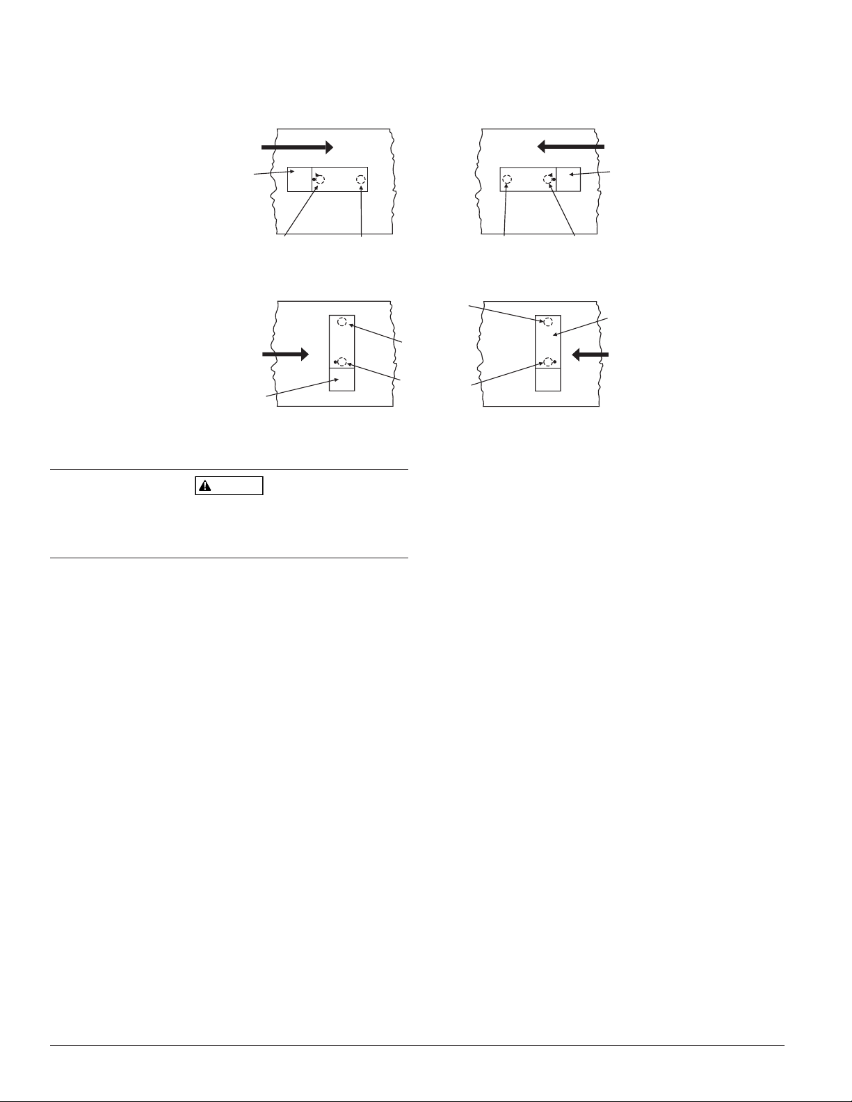
WA RNING
AIR FLOW
DIRECTION
DETECTOR
HOUSING
DOTS INDICATE POSITION OF
SAMPLING TUBE HOLES
AIR FLOW
DIRECTION
DETECTOR
HOUSING
INLET
TUBE
EXHAUST
TUBE
AIR FLOW
DIRECTION
EXHAUST
TUBE
INLET
TUBE
INLET
TUBE
EXHAUST
TUBE
DETECTOR
HOUSING
AIR FLOW
DIRECTION
EXHAUST
TUBE
INLET
TUBE
DETECTOR
HOUSING
A.
B.
C.
D.
HORIZONTAL MOUNTING OF HOUSING
VERTICAL MOUNTING OF HOUSING
Figure 4. Tube mounting configurations with varying air flow direction and orientation of detector housing.
Ver tical as well as horizontal mounting is acceptable.
H0109-00
NOTE: An alternate method to using the ST-10 is to use
In no case should more than 2 air inlet holes be cut off the
tube. There must be a minimum of 10 holes in the tube
exposed to the air stream.
B. Installation for Ducts More Than 8 Feet Wide
NOTE: To install inlet tubes in ducts more than 8 feet
wide, work must be performed inside the air duct.
Sampling of air in ducts wider than 8 feet is accom-
NOTE: Air currents inside the duct may cause excessive
plished by using the ST-10 inlet sampling tube.
Install the inlet tube as follows:
1. Drill a 3/4-inch hole in the duct directly opposite the
hole already drilled for the inlet tube.
2. Slide the inlet tube with the flange into the right housing
bushing. Position the tube so that the arrows point into
the air flow. Secure the tube flange to the housing bushing with the two #6 self-tapping screws.
3. From inside the duct, couple the other section of the
inlet tube to the section already installed using the 1/2inch conduit fitting supplied. Make sure the holes on
both of the air inlet tubes are lined up facing the air
flow.
4. Trim the end of the tube protruding through the duct so
that 1 to 2 inches of the tube extends outside the duct.
Plug this end with the tube end cap and tape closed any
holes in the protruding section of the tube. Be sure to
seal the duct when the tube protrudes.
5. Any tube (over 3 feet long) that doesn’t protrude through
the duct (on the side opposite the housing) must be supported by other means.
D500-08-00 4 I56-512-07R
Modification of Inlet Sampling Tubes
There may be applications where duct widths are not what
is specified for the installation. In such cases, it is permissible to modify an inlet sampling tube that is longer than
necessary to span the duct width.
Use a 0.193-inch diameter (#11) drill and add the appropriate number of holes so that the total number of holes
exposed to the air flow in the duct is 10 to 12. Space the
additional holes as evenly as possible over the length of
the tube.
two ST-5 inlet tubes. Remove the flange from one
of the tubes and install as described above. After
the installation, use electrician’s tape to close off
some of the sampling holes so that there are a total
of 12 holes spaced as evenly as possible across the
width of the duct.
vibration. This vibration can slowly open the
seal around the tube and permit air to escape. To
prevent this from occurring, a 3-inch floor flange,
available at most plumbing supply houses, may be
used. This flange/connector mounting technique
makes the initial installation easier because a 1inch to 1-1/4-inch hole may be drilled where the
flange/connector will be used. It is easier to push
the inlet tube through the larger hole.
Page 5

NOTE: This procedure should only be used in an emergen-
CAUTION
SAMPLING TUBE
FILTERS
SAMPLING TUBE
MOUNTING
SCREWS
DETECTOR HEAD
EXHAUST
FILTER ADAPTER
DETECTOR BASE
INLET SAMPLING TUBE
FOAM GASKET
cy, and it is not intended as a permanent substitute
for ordering the correct length tubes.
left, as shown in Figure 6. Then install the other filter over
the end of the inlet sampling tube.
Step 5. Field Wiring
Wiring Installation Guidelines
All wiring must be installed in compliance with the
Canadian Electrical Code and the local codes having jurisdiction. Proper wire gauges should be used. The conductors used to connect smoke detectors to control panels and
accessory devices should be color-coded to prevent wiring
mistakes. Improper connections can prevent a system from
responding properly in the event of a fire.
For signal wiring, (the wiring between interconnected
detectors or from detectors to auxiliary devices), it is recommended that single-conductor wire be no smaller than
16 gauge (1.5 square mm), and that two- or three-conductor wire be no smaller than 18 gauge (1.0 square mm). The
last foot or so of conduit should be flexible steel conduit
(available in electrical supply houses) which facilitates
easier installation and puts less strain on the conduit holes
in the housing. Solid conduit connections may be used if
desired.
Smoke detectors and alarm system control panels have
specifications for allowable loop resistance. Consult the
control panel manufacturer’s specifications for the total
loop resistance allowed for the particular model control
panel being used before wiring the detector loop.
Wiring Instructions
The DH500 is designed for easy wiring. The housing provides a terminal strip with clamping plates. Wiring connections are made by stripping approximately 1/2-inch of
insulation from the end of the wire, sliding this bare end
under the plate, and tightening the clamping plate screw.
Filters require periodic cleaning or replacement, depending on the amount of dust and dirt accumulated. Visually
inspect the filters at least quarterly; inspect them more
often if the dust accumulation warrants it. Replacement
filters can be ordered from System Sensor (exhaust tube/
intake tube filter P/N F36-05-00).
The filters do not substantially affect smoke performance
under normal conditions. There is very little restriction of
smoke entry even when up to 90% of the filter is clogged.
Visual inspection is usually adequate to determine whether
the filters should be replaced because such a high percentage of contamination is required to affect performance.
However, if further testing is desired, a Dwyer Model 460
(or equivalent) Differential Pressure Gauge may be used.
Simply compare the differential pressure readings with
and without the filters attached. There should be little or
no difference. If the difference exceeds 10%, replace the
filters. In no case, however, should the pressure differential
be less than 0.01 inches of water or greater than 1.2 inches
of water.
Step 7. Per form Detector Check
7.1 Air Flow
1. To verify sufficient sampling of ducted air, use a manometer to measure the differential pressure created from
air flow across the sampling tubes. The pressure should
measure no less than 0.01 inches of water and no greater
than 1.20 inches of water.
Figure 6. Sampling tube filter installation:
Step 6. Install the Filters
Most duct installations are subject to dust accumulation.
System filters remove a large percentage of this contamination, but cannot remove all of it. Dust inside the duct
detector causes problems. First, very fine particles of dust
can enter the detector sensing chamber and cause the unit
to go into alarm. Second, the accumulation of dust and dirt
necessitates a more frequent periodic cleaning schedule,
which can result in substantial cost and/or down time.
Disposable sampling tube filters can greatly reduce the
nuisance alarms caused by dust, and can also significantly
extend the maintenance interval. To install the sampling
tube filters, simply push the filter adapter into the exhaust
tube, and then push the filter onto the adapter tube on the
D500-08-00 5 I56-512-07R
H0294-00
Page 6

(+)
(-)
RA400
REMOTE ALARM
LED OPTION
1 PER UNIT
8mA CURRENT DRAW
RA400Z (+)
RA400Z or (-)
RTS451/
RTS451KEY
EXTERNAL
(-) POWER (+)
SUPPLY
*
RTS451/RTS451KEY
REMOTE TEST STATION
LED OPTION
1 PER UNIT
8mA CURRENT DRAW
TEST COIL OPTION
1 PER UNIT
95mA CURRENT DRAW
45
321
Unused
Remote
Test
(+)
(-)
(+)
(+)
(-)
(-)
(+)
RA400Z
RTS451/RTS451KEY
RA400Z or
RTS451/RTS451KEY
Comm.
Line
Comm. Line (+)
Alarm
Initiation
Loop
Comm.
Line (-)
UL Listed
Control Panel
1st
Detector
in Loop
2nd
Detector
in Loop
The RTS451/RTS451KEY test coil circuit requires an external 24VDC
power supply which must be UL listed
*
Figure 5C. System wiring diagram
for duct detectors using a UL listed
control panel.
Figure 5A.
Figure 5B.
H0295-00
D500-08-00 6 I56-512-07R
Page 7

TWIST
COUNTERCLOCKWISE
TO REMOVE
DUCT
HOUSING
TWIST
CLOCKWISE
TO INSTALL
DETECTOR
HEAD
MOLDED RIB
TEST
MAGNET
PAINTED SIDE
TOWARD HOUSING
DUCT
DETECTOR
HOUSING
DETECTOR
HEAD
2. To determine that smoke is capable of entering the sens-
CAUTION
ing chamber, a visual examination should be conducted
Figure 8. Detector head removal:
to note any obscurations around the sensing chamber. If
a smoke test is required, smoke such as cigarette, cotton wick, or punk smoke may be blown directly at the
smoke detector head. It is important to plug the exhaust
and sampling tube hole to prevent ducted air from blowing smoke away from the smoke detector head. Record
all test records in the Detector Test Log (page 12).
Remember to remove the plugs after this test or the detector will not sense smoke in the air duct.
7.2 Alarm Tests
Before replacing the duct housing cover, the detector
interconnections should be checked. The DH500 may be
checked as follows:
A. M02-04-00 Magnet Test
1. Make sure power is applied to the detector.
2. Place the painted surface of the test magnet against
the housing next to the rib molded onto the outside
of the housing (see Figure 7).
3. The LEDs on the detector should latch on as should
any accessories (i.e. RA400ZA, RTS451), and the
alarm condition should be verified at the control
B. RTS451/RTS451KEY Remote Test Station
The RTS451/RTS451KEY Remote Test Station facilitates test
of the alarm capability of the duct detector as indicated in
the RTS451/RTS451KEY manual. The DH500 duct detector
cannot be reset by the RTS451/RTS451KEY. It must be reset
at the system control panel.
panel.
To install the RTS451/RTS451KEY test coil, connect the
device as shown in Figure 9; wire runs must be limited to
Figure 7. Testing detector
25 ohms or less per interconnecting wire. Place the coil in
the detector housing with the arrow facing up and pointing
toward the detector as in Figure 9. Attach the coil leads to
the housing terminals as shown; polarity is not important.
Firmly screw the bracket in place over the test coil.
7.3 MOD400 Sensitivity Test
After verification of alarm capability, the MOD400 test
module may be used with a voltmeter to check detector
sensitivity as indicated in the MOD400 installation manual.
The housing cover must be removed to perform this test.
H0276-00
If the MOD400 readings indicate that the detector head is
H0275-00
outside of the acceptable range, the detector head requires
cleaning. (See Periodic Maintenance Requirements on page
9.)
7.4 Trouble Test
The capability of “TROUBLE” detection is tested by removing the detector head from the duct housing. The detector
head is removed by turning it counterclockwise about 10
degrees (Figure 8). The system control panel should indicate a trouble condition. Reinserting the detector head
should clear the trouble condition.
D500-08-00 7 I56-512-07R
Page 8
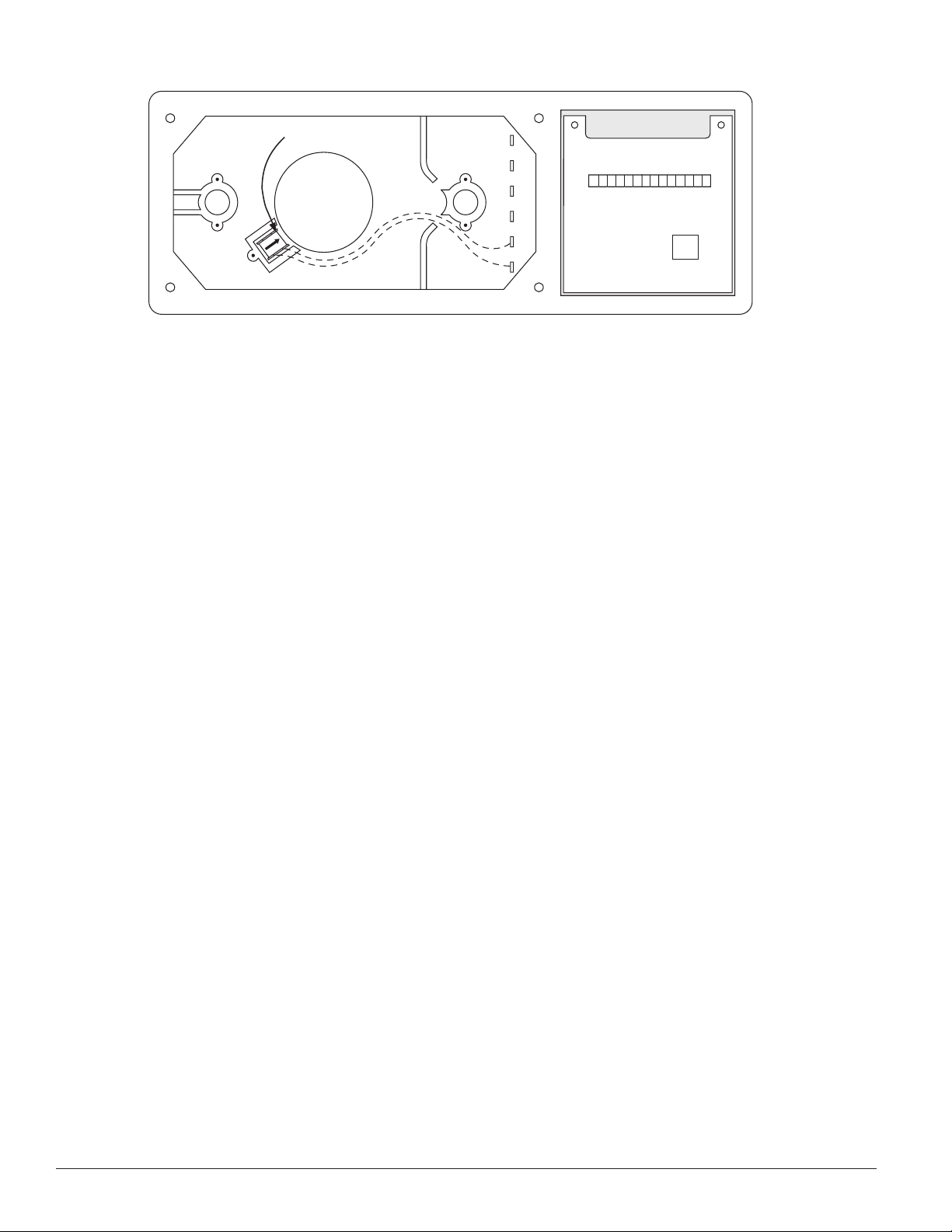
DETECTOR
HEAD
TEST COIL
Figure 9. RTS451/RTS451KEY test coil installation:
H0292-00
Step 8. Install the Cover
Install the cover using the four screws. Be certain filters are
installed as specified in Step 6. Make sure that the cover fits
into the base groove and that all gaskets are in their proper
positions. Tighten the four cover screws to 10 in/lbs.
Step 9. Per form the Final System Check
Place the magnet in position as shown in Figure 7. The
LEDs on the detector should light. Any accessory LED(s)
will also light. The system control panel should indicate an
alarm condition.
Periodic Maintenance Requirements
Air duct smoke detectors should be maintained at least
once a year. They should be maintained more often if the
detector heads become obviously dirty in less than a year.
The detectors must also be cleaned immediately after a fire.
Failure to properly maintain air duct smoke detectors may
cause unnecessary false alarms.
It is recommended that a permanent Detector Test Log be
set up and maintained, with a record for each individual
smoke detector in each building. Each detector should be
clearly described, with information on the type of detector,
the model number, the serial number (if any), the location,
and the type of environment. Data entries should include
test dates, type of test mode, test results, maintenance, and
comments. A detector test log is included in this manual.
Recommended Detector Maintenance Procedure
NOTE: Notify the proper authorities that the smoke detec-
tor system is undergoing maintenance, and therefore the system will temporarily be out of service.
Disable the zone or system undergoing maintenance to prevent unwanted alarms and possible
dispatch of the fire department.
1. Turn off power to the system.
2. Remove and inspect sampling tube filters.
3. If filters are heavily coated with dirt, replace them with
new filters. If they are not heavily coated, use a vacuum
cleaner or compressed air nozzle to remove dust, then
reinstall the filters.
4. Remove detector from housing. (See Figure 8.)
Photo Units
5. Remove detector cover by inserting a small blade screwdriver into the slot located 90 degrees from the MOD400
test jack receptacle, twisting the cover counterclockwise
to remove (see Figure 10).
6. Lift screen from photo chamber. Vacuum screen and
cover before using clean, compressed air to loosen and
blow out any remaining debris. (Replacement screens
are available, part no. RS24.)
7. Vacuum photo chamber, then use clean compressed air
to blow area clean.
8. Replace screen by aligning arrow on top with the field
test slot on the base of the detector. Push screen into
place. Screen should fit tightly to chamber.
Ionization Units
9. Remove the detector cover and screen assembly by
depressing the three lock prongs on the top of the cover
and rotating the cover counterclockwise. The CRT400
Cover Removal Tool makes cover removal easier. (See
Figure 11.)
10. Carefully pull the screen out of the cover.
11. Clean the screen thoroughly with a soft brush or vacu-
um (replacement screen available, part no. RS14).
12. Brush or vacuum the inside of the cover. Cover may
then be blown out using clean, compressed air. DO
NOT APPLY WATER TO THIS AREA.
13. Vacuum the sensing chamber before using clean,
compressed air to loosen and blow out any remaining
debris. DO NOT APPLY WATER TO THIS AREA.
14. Press the screen back into the cover.
15. Replace the detector cover and screen assembly on
the sensing chamber. Rotate it clockwise to lock it into
place.
D500-08-00 8 I56-512-07R
Page 9

Both Types Of Units
CAUTION
REMOVABLE HEAD COVER
CLEANABLE SCREEN
HEAD COVER
REMOVAL SLOT
TEST SLOT
VANED CHAMBER
P/N RS24 (W/O THERMAL)
HOUSING
LOCK PRONGS
REMOVABLE SCREEN
(P/N RS14)
REMOVABLE
COVER
FOR
CLEANING
HEAD COVER
LOCK PRONGS
16. Reinstall the detector housing.
17. Restore power to the system.
18. Put detector into alarm using appropriate method
described in STEP 7. PERFORM DETECTOR CHECK
(page 7 of this manual).
19. Notify the proper authorities that testing has been
completed and the smoke detector system is again
operational.
20. Other checks that should be made during mainte-
nance procedures:
–Holes or cracks in duct work near vicinity of detec-
tor
–Air leaks where detector housing or sampling tubes
are attached to duct
–Dust accumulations in or on sampling tubes
–Wiring terminal screw tightness
Accessories Part No.
Remote LED RA400ZA
Remote Test Station RTS451/RTS451KEY
Piezo Alert Sounder PA400
Replacement Filters F36-05-00
Magnet M02-04-00
End Plug For Sampling Tube P48-21-00
Installation Kit (Parts bag) A2650-01
Ionization Replacement Screen RS14
Sensitivity Test Kit MOD400
Ionization Cover Removal Tool CRT400
Programming Specifications/Requirements for
Intelligent System Control Panels
The 1551 and 2551 models can be used with the DH500 if
the following constraints are observed.
There is a limit to the number of devices per zone that can
have their LEDs latched ON. The actual number of devices
is determined by the control panel and its ability to supply
LED current. Refer to the equipment manual supplied by
the control panel manufacturer for details.
Figure 10. Photo head exploded view:
H0261-00
Figure 11. Ion head exploded view:
H0296-00
D500-08-00 9 I56-512-07R
Page 10

D500-08-00 10 I56-512-07R
Page 11

Please refer to insert for the Limitations of Fire Alarm Systems
Three-Year Limited Warranty
System Sensor warrants its enclosed smoke detector to be free from
defects in materials and workmanship under normal use and service for a
period of three years from date of manufacture. System Sensor makes no
other express warranty for this smoke detector. No agent, representative,
dealer, or employee of the Company has the authority to increase or alter
the obligations or limitations of this Warranty. The Company’s obligation of this Warranty shall be limited to the repair or replacement of any
part of the smoke detector which is found to be defective in materials or
workmanship under normal use and service during the three year period
commencing with the date of manufacture. After phoning System Sensor’s
toll free number 800-SENSOR2 (736-7672) for a Return Authorization
number, send defective units postage prepaid to: System Sensor, Repair
D500-08-00 11 I56-512-07R
Department, RA #__________, 3825 Ohio Avenue, St. Charles, IL 60174.
Please include a note describing the malfunction and suspected cause
of failure. The Company shall not be obligated to repair or replace units
which are found to be defective because of damage, unreasonable use,
modifications, or alterations occurring after the date of manufacture. In
no case shall the Company be liable for any consequential or incidental
damages for breach of this or any other Warranty, expressed or implied
whatsoever, even if the loss or damage is caused by the Company’s negligence or fault. Some states do not allow the exclusion or limitation of
incidental or consequential damages, so the above limitation or exclusion
may not apply to you. This Warranty gives you specific legal rights, and
you may also have other rights which vary from state to state.
Page 12

DETECTOR TEST LOG
Detector Identification Information
Manufacturer and Serial Date
Detector Model:______________________ Number: ______________________ Installed: ___________________
Description of Detector Location:
________________________________________________________________________________________________
________________________________________________________________________________________________
________________________________________________________________________________________________
Test Results and Maintenance Data
Date Test Test Maintenance
Tested Description Results Performed Comments
_______ _________ ______ __________ ______________________
_______ _________ ______ __________ ______________________
_______ _________ ______ __________ ______________________
_______ _________ ______ __________ ______________________
_______ _________ ______ __________ ______________________
_______ _________ ______ __________ ______________________
_______ _________ ______ __________ ______________________
_______ _________ ______ __________ ______________________
_______ _________ ______ __________ ______________________
_______ _________ ______ __________ ______________________
_______ _________ ______ __________ ______________________
_______ _________ ______ __________ ______________________
_______ _________ ______ __________ ______________________
_______ _________ ______ __________ ______________________
_______ _________ ______ __________ ______________________
_______ _________ ______ __________ ______________________
_______ _________ ______ __________ ______________________
_______ _________ ______ __________ ______________________
D500-08-00 12 I56-512-07R
© 2003 System Sensor
 Loading...