

Page 1
CONTENTS
Radio Basics.................................1
The RF Waveband 1
The RF Network 1
RF Signal Characteristics 1
RF Signal Attenuation 2
Agile™ 200 Series RF Fire System ............... 3
The Concept of Mesh Hierarchy 3
Network Synchronisation 4
The Back-up Node 4
Site Survey ..................................4
What is a Site Survey 4
Why is it Necessary 4
How to Plan a Site Survey 4
What to Take to a Site Survey 5
Summary of Basic RF Site Survey Principles 5
Some Guidelines for using the Agile™ 200 Series
Radio System ................................6
Agile™ System Coverage 6
Measuring Wall Attenuation 7
Not Able to Generate a Network 7
How to Resolve a Poor Link Quality 7
RF Do’s and Don’ts 8
Do’s 8
Don’ts 9
AGILE™ RADIO FIRE DETECTION SYSTEM
APPLICATION and INSTALLATION GUIDELINES
RF BASICS
The RF Waveband
Radio frequency (RF) devices use radio waves to communicate
(transmit and receive data) in the form of coded radio signals. The
RF waveband (part of the electromagnetic spectrum) ranges from
a few kHz to hundreds of GHz and can be divided up into different
sections, with different radio characteristics and capabilities.
The Agile™ 200 Series RF re system uses a frequency range
based around 868MHz in the UHF region (the lower end of
microwaves); that is a wavelength of 346mm.
Short-range, low-power RF Systems are becoming more popular
for a wide range of applications; within re and security products
they are often used in temporary installations or situations where
building work and unsightly cabling cannot be tolerated.
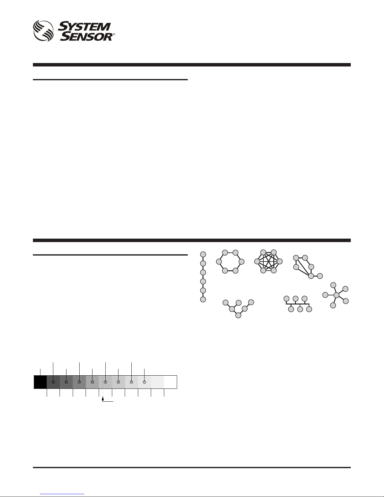
The RF Network
Agile™ 200 Series RF devices can transmit and receive, they are
transceivers. When two devices communicate directly with one
another, they have set up a link; the devices at each end of a link
are known as nodes. A set of devices (or nodes) communicating
together is called a network. There can be a wide range of network
topologies, as shown in the examples following:
VLF LF MF HF VHF UHF SHF EHF IR Visible light
10kHz
100kHz
1MHz
10MHz
100MHz
1GHz
10GHz
100GHz
1000GHz
System Sensor 200 Series RF
THF
Ring
Star
Fully
Connected
Line
Tree
Bus
Mesh
RF Signal Characteristics
Fundamentally radio signals, like light, travel in straight lines. And
in the same way as light they can be affected by objects in their
path. Forming part of the electromagnetic energy spectrum, they
are capable of transmission through some materials, absorption by
others and can be reected, refracted and diffracted. The effects
on radio waves caused by different materials are dependent upon
the material’s properties.
Metallic surfaces are excellent reectors of radio frequency
(RF) energy; water and wet areas may also be good reectors.
Refraction occurs when electromagnetic waves pass across
a boundary between materials of different densities (refractive
index) and diffraction can occur when signals pass close to large,
particularly sharp, objects. Attenuation in different materials
(resulting from energy absorption and high frequency scattering)
is caused by the material’s molecular characteristics, structure and
resonances at different wavelengths.
In an open space, the power reduction down a signal path is
proportional to the square of the distance from the transmitter (see
Figure 1 following).
Page 2
2
A05-0473-010
1
1
2
2
d
2xd
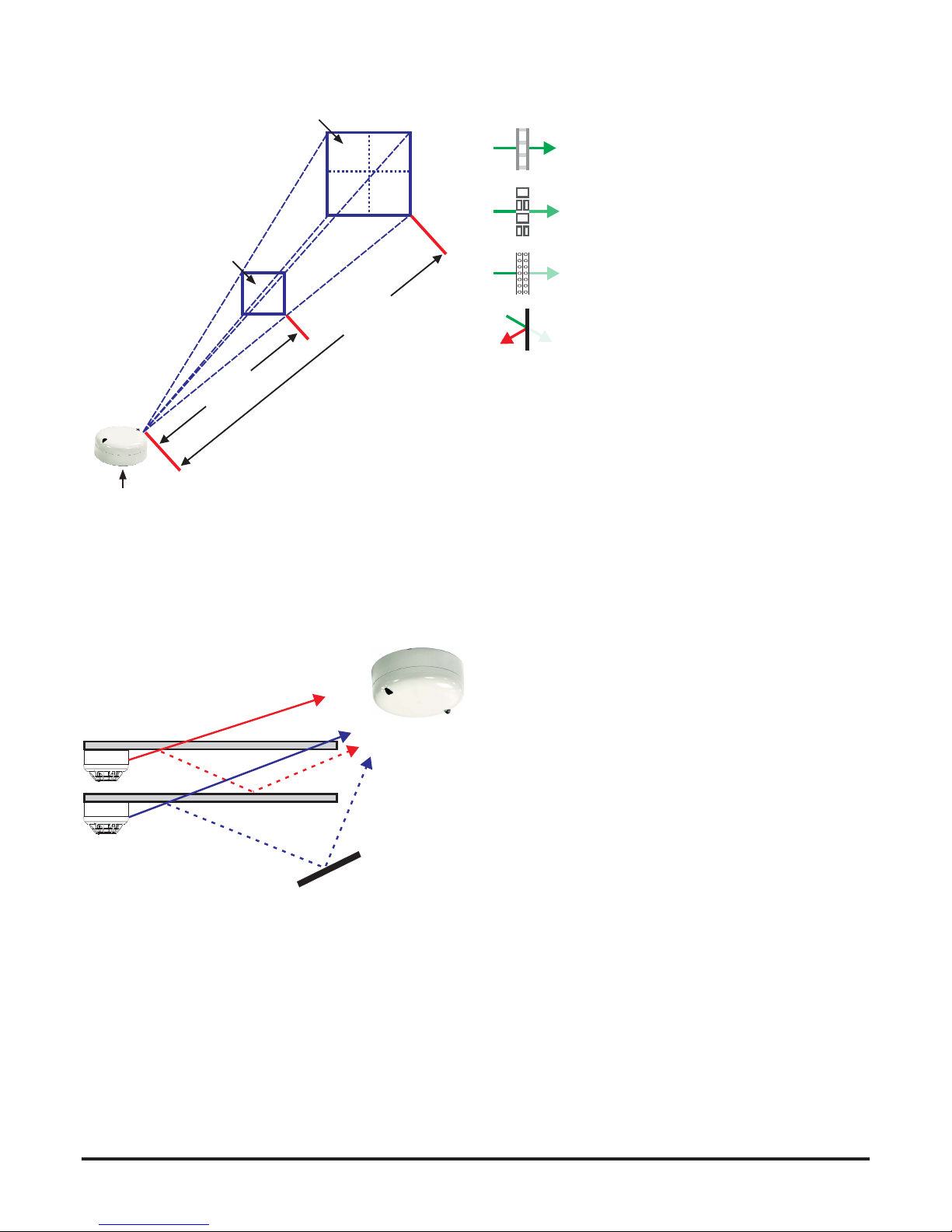
RF Signal Attenuation
In addition to this square law attenuation, signal strengths inside a
building will also vary from place to place owing to destructive and
constructive interference caused by signals arriving with different
phases, resulting from different path lengths (see Figure 2).
The Agile™ 200 Series RF devices have a typical transmission
range in free air of up to 500m, but within an ofce or factory
environment, signals can come into contact with many objects in
a range of materials such as ceilings, oors and walls at different
angles, desks, ling cabinets and a variety of plant and machinery.
There are numerous opportunities for reection, refraction and
absorption and all these things will probably reduce the effective
range, even in an open plan environment, to not much more than
about 100m.
Some common building materials are listed in Table 1 together
with typical energy loss gures which can be expected. A normal
double brick wall, for example, can reduce a signal’s strength
by up to a third or more. All these factors will contribute to the
occurrence in a building of areas of varying signal strengths and
reception characteristics.
Figure 1: Relationship Between Distance and RF-Power
SURFACE AT DISTANCE 2d
SURFACE AT DISTANCE d
SURFACE MEASURES 1M2 AT DISTANCE d
SURFACE MEASURES 4M2 AT DISTANCE 2d
WHEN THE DISTANCE IS DOUBLED, THE FIELD
STRENGTH IS REDUCED BY A FACTOR OF 4
RADIO GATEWAY
Figure 2: Different RF Signal Paths
Table 1: Energy Loss with Different Materials
Designing and installing an RF system in areas with large radio
eld absorption, e.g. with metallic lattice partitions, large metal
vessels or with tall metallic storage racks may be very challenging.
Material Type Energy Loss
Wood and plasterboard 0 – 10%
Solid brick 5 – 35%
Steel reinforced concrete 30 – 90%
Metal plates, under oor heating 90 – 100%
Page 3
3
A05-0473-010
AGILE™ RF FIRE SYSTEM
The Agile™ 200 Series RF re system is designed for use with
compatible intelligent re systems using the System Sensor
200/500 Series CLIP, Enhanced and Advanced communication
protocols. Devices signalling from the radio domain are translated
by the RF gateway into addressable loop communication signals
recognized by the Control and Indicating Equipment (CIE). Each
device has its own physical address on the loop, selected using
two rotary switches, which can be manually set in a range between
1 and 99 or 1 and 159 depending on the loop protocol used by the
panel.
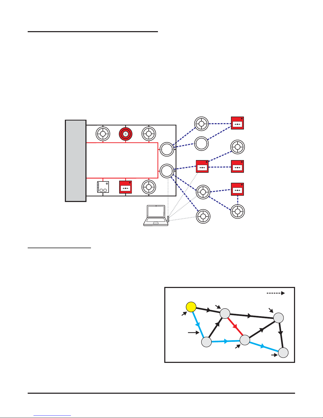
The system architecture can be characterised as shown in Figure 3
following.
Figure 3: System Overview
WIRED FIRE SYSTEM
WIRELESS FIRE SYSTEM
CIE
DETECTOR
SOUNDER /
STROBE
GATEWAY
REPEATER
WIRELESS
DETECTOR
WIRELESS CALL
POINT
LAPTOP / PC
RUNNING
AgileIQ™
USB
INTERFACE
(DONGLE)
MODULE CALL POINT
The red and black lines show the wired loop; the dotted
blue lines represent the RF communication. A PC has
the ability to communicate with all the wireless devices
using a special software application (AgileIQ™) and
USB transmit/receive interface dongle.
Figure 4: Mesh Hierarchy
The Agile™ RF Mesh Network
When two devices in a network can communicate directly, they
are said to have a link. The devices at each end of a link are
known as nodes and a network is made up of a set of nodes and
links. For the 200 Series RF system, each RF device can receive
and transmit wireless information and hence each RF link has bidirectional communication.
As every RF device is a transceiver the network can be organized
to minimize the use of repeaters. This is achieved by allowing each
device to receive and re-transmit information from its neighbours
on to the master device (the gateway).
The Concept of Mesh Hierarchy
When there is a direct path between nodes, say from device #1
to device #2, the two nodes are linked. Within the mesh there
are the concepts of ‘parents’ and ‘children’, and ‘ancestors’ and
‘descendants’, moving in the direction from the gateway to the
mesh boundary. So, whilst links have bi-directional communication,
there is also a concept of link directionality with respect to the order
or ranking of each of the devices. This is why links are shown with
directional arrows, establishing the hierarchy of the nodes.
In the Agile™ RF system, each node can have up to 6 active links
with its neighbours; 2 links going toward the gateway (one from
each of its 2 parents) and up to 4 links going toward the network
boundaries (i.e.to 4 children). A gateway is a special RF node and
can have up to 32 links.
Node
Directional
Link
Parent
Ancestor
Child
Descendant
4
1
3
5
2
6
Direction of Mesh Boundary
In general, to satisfy the Agile™ mesh protocol criteria in terms
of hierarchy and timings, all nodes should be descendents of the
gateway, (i.e. there must be a chain of primary links to/from the
gateway) and each device will have one primary link to a parent
and one secondary link to its other parent. All links from a gateway
will be primary links.
Note the unique and important Back-up Node #2; this has only one
parent – the gateway. Its importance in the network is described
below.
Page 4

4
A05-0473-010
Network Synchronisation
When Agile™ devices transmit data they require a lot of energy.
Therefore, to maintain low battery power consumption, the devices
are not in transmit/receive mode all the time; for much of the time
they will be in a very low power (silent) mode.
To communicate properly, the devices in the network must all
transmit and receive at the same time. To do this, the communicating
periods must be synchronised so that devices wake up together
from their silent state to move data to and fro before going silent
again. This synchronisation of the network is orchestrated by the
gateway which maintains a constant ‘drum-beat’ throughout the
mesh system.
In the Agile™ 200 Series RF Fire System, a complete cycle of
transmit/receive windows takes approximately 5 seconds including
the silent periods.
Figure 5: Synchronised Communication Sequence
5s approx.
~s½ ~s½
~s½
Time
REQ 1
(->GW)
REQ 2
(->GW)
RESP
(GW->)
The Back-up Node
A mesh network that is operating normally is kept in sync by the
Gateway. But if a gateway is removed from a system or is powered
off, control of the network will be lost. All the devices will continually
try to re-connect with the missing gateway and this will lead to high
battery power consumption and signicantly reduce the battery life,
unless all the batteries are removed from the Agile™ RF devices.
To prevent this situation (for example, during a re system
maintenance period), a special node has been created in the mesh
that takes over the network synchronisation role should a gateway
go ‘missing’. Hence, the network continues to operate, but in a
low power (idle) state, minimising battery usage across the system
while the gateway is off. Obviously, during this time, the Agile™ RF
system will not be providing re cover.
It can take up to 12 minutes for a backup node to assume control of
the network, after the gateway has been switched off. It may take
up to 10 minutes for the gateway to reclaim control of the network,
when the gateway is re-powered on.
SITE SURVEY
What is a Site Survey?
Great care needs to be taken when assessing a site and choosing
the right technology and design layout to use; wireless systems
may not be suitable for every situation. Before committing to a
design and physical implementation of a wireless re system it is
important to understand and ‘visualise’ the eld strength of the RF
network to ensure that vital areas of the building have adequate
signal coverage.
A site survey needs to be done to ensure that the RF re system
will work reliably after installation.
A site survey involves the use of the AgileIQ™ Software Tools
and Site Survey equipment to carry out RF energy scans and RF
link quality checks. The RF energy scan identies any channel
frequencies that are unsuitable and the link quality check ensures
that RF communications between nodes is acceptable.
Why is it Necessary?
A site RF survey is a critical element in the process of designing
and installing a wireless communications network in an ofce
or building. The survey will determine the best placement of the
sensors and manual call points to comply with the coverage and
positional requirements of the re regulations in the designated
location.
In the UK, the Code of Practice for system design, installation,
commissioning and maintenance of re detection and alarm
systems (BS5839-1: 2002) specically addresses the need to carry
out an RF site survey. Section 27.2 states that installation of a
radio-linked system should only take place after a comprehensive
radio survey has been undertaken to ascertain the following:
● There are no other potentially interfering radio sources
● Thereisadequatesignalstrengthforcommunication
The Code also requires that only radio survey test equipment
approved by the manufacturer should be used and records of
signal readings should be kept for future reference.
When doing a site survey, give adequate consideration to how
the site will be used when the Agile™ RF system is working. For
example, make sure that doors and windows are closed when
signal strength measurements are being taken.
And when installing an Agile™ RF system, it is important to ensure
that there have been no changes to the areas within a building,
such as new internal walls or partitions, the introduction of tall
metal enclosures or the introduction of other wireless systems
since the original site survey was carried out. Any changes to the
system design or the building may require an extra site survey to
conrm the wireless re system will still work reliably.
How to Plan a Site Survey
The RF energy and link quality tests are important as they ensure
the RF re system will work reliably in the building where it is
installed.
It is preferable to preplan how the tests will be carried out during
the site survey visit. Use a plan-view of the building to identify the
likely positions of devices with respect to customer requests, local
regulations and re systems requirements. Identify each device
location with a device type and unique code. Consider how the RF
mesh network will provide coverage across the site, being mindful
of the potential attenuation that walls and other objects can cause.
Site layout drawings can be marked up manually to show the
planned positions of devices, or an electronic copy of the site layout
drawings can be loaded into the Agile IQ™ Software Application to
assist with a site survey. Using the Agile IQ™ design feature, it is
possible to draft a layout diagram of the Agile™ RF devices, create
Page 5

5
A05-0473-010
a mesh network and generate a list of RF links associated with the
network.
Be sure to note or mark up any changes to position of devices, or
the introduction of new devices, created during the survey.
NOTE: Do not run more than one RF interface (dongle) at a
time in an area during a site survey.
What to take to a Site Survey
The following equipment is the minimum that will be required to
carry out an RF site survey.
● PC/Tablet running the AgileIQ™ RF PC Tools software application
● USB RF interface (Dongle)
● Two Agile™ radio sensors in RF bases
● Set of Duracell 123 batteries
System Sensor can supply a range of additional equipment to
assist with the site survey.
Available options are:
● POLEHWKIT-1.5m–5.2mTelescopicpole
● CUPHWKIT– Cup to holdAgile™radiodevice and base in
position on pole
● SOLOADAPTHWKIT–AdaptorthatallowstheCUPHWKITto
beconnectedtoaSOLO*accesspole
● BAG RF HWKIT – Survey bag to store and carry poles and
cupsetc.
* Available from Detection Testers/No Climb.
Note: The USB interface may need a mini-USB adaptor to be used
with a Notebook/Tablet.
The picture shows a device holder (CUP HWKIT) mounted on an
extension pole (POLE HWKIT).
Summary of Basic RF Site Survey Principles
1) Site diagram: Obtain or create a facility diagram or oor plan
drawing that depicts the location of walls, walkways, etc.
2) Visual inspection: Walk through the facility to verify the
accuracy of the facility diagram. Add any potential barriers that
may affect the propagation of RF signals such as metal racks
and partitions, items that are not shown on the oor plan.
3) Device positions: Determine the preliminary location of
devices; be certain to consider mounting options. Make
sure all doors and windows etc are closed when the survey
measurements are taken.
4) Verify RF link quality: Take note of signal readings at the
different device locations, moving through the site. (In a multi-
level facility, perform signal checks on the oors above and
below.) Based on the results of the testing, it may be necessary
to relocate some devices and redo any affected tests. Where
appropriate, introduce an additional device or a repeater to
form a bridge between two locations with a weak link.
5) Document the ndings: Once satised that the planned
location of devices will have adequate link quality, identify them
clearly on the facility diagrams and add all relevant notes to the
project; the installers will need this information. Also, provide
a log of signal readings for reference and as support for any
future network additions or redesign.
The use of the Agile IQ™ software application will provide a high
level of assistance in accomplishing these tasks quickly and
efciently.
Page 6

6
A05-0473-010
SOME GUIDELINES FOR USING THE AGILE™ 200 SERIES RADIO SYSTEM
Agile™ System Coverage
When designing and installing a System Sensor Agile™ radio
mesh network, consideration should be given to the following.
Agile™ RF radio devices appear as wired elements to a re panel.
Check to ensure the maximum number of combined wired and
wireless devices on a loop has not been exceeded (198 in CLIP
or 318 in AP)
Conrm that detector types and spacing requirements, sounder
and strobe coverage and exits that need manual call points have
been identied as required by national and local regulations (for
example in the UK, the recommendations of the Code of Practice
BS5839 Part 1 should be followed).
The Agile™ radio system can have up to 8 Gateways operating in
the same area. There is also a maximum limit of 32 devices allowed
per Gateway. In the UK, ensure the radio system associated with
a gateway does not cover more than one zone as dened by
BS5839 Part 1.
Consider the best location for the gateway with respect to both its
connection to the wired loop and its need to control a group of radio
devices. See section headed Do’s and Don’ts.
Identify any radio device locations that may have difculty
communicating with at least 2 other devices in the mesh. It may
be necessary to introduce additional nodes to bridge poor links
(see RF Signal Attenuation section). It is important to note that
RF signals will be attenuated differently depending on the type and
construction of any obstructions.
Therefore, a system design should take into account obstructions
and the level of signal attenuation caused by:
● Wall type and thickness
● Structural supporting beams
● Tall metal cabinets (such as those that are from oor to ceiling
and IT equipment in tall metal enclosures)
A system design should also consider the site operating conditions,
like:
● Strong local interferences (such as from certain types of
communications devices and RFID readers)
● Site changes, such as construction of new internal walls
● Placement of large metal objects, water storage tanks etc.
● Areas where large objects move regularly, loading bays, lift
shafts, goods storage
● Possible reections from close-by buildings or other objects
where attenuation may vary with the environment (e.g. rain)
● Whilst Agile™ devices are designed to be omni-directional
in performance, note any signicant signal strength variation
with device rotation; use the mark on the detector base as a
reference
Remember that radio signals travel in 3 dimensions, for example,
upwards or downwards as well as forward/backwards directions.
Note that the RF Link Quality may be good between devices on
adjacent oor levels as well as between devices on the same oor
level. This is dependent on the construction of oor and ceiling.
Figure 6 shows the arrangement that may be suitable where the
oor construction prevents RF signal between oor levels, while
Figure 7 may be suitable where the RF signal can be strong (good)
between oor levels.
Figure 6: Arrangement Where the Floor Construction
Prevents RF Signal Between Floor Levels
Figure 7: Arrangement Where the RF Signal
can be Strong (Good) Between Floor Levels
LEVEL 1
LEVEL 0
LEVEL 1
LEVEL 0
Page 7

7
A05-0473-010
Measuring Wall Attenuation
The following method can be used to record the actual RF signal
attenuation caused by a wall.
1) In the room containing the wall to be measured, take a Link
Quality measurement across an open part of a room. Set up
the two measuring devices with device #2 nearest to the wall to
be checked. The dongle should be within range (a few metres)
of device #1.
2) When satised that the measurement is stable, STOP the
recording and make a note of the attenuation value.
3) Move device #2 to the other side of the wall, ensure it is in the
same orientation as before and take a second measurement,
again noting the attenuation value.
4) Subtract the rst attenuation value from the second attenuation
value; the result is the attenuation in signal strength resulting
from the wall. This gure can be used for the wall attenuation in
the design simulation and should be entered into the Edit Wall
information box as a Custom value.
Not able to generate a Network
If the mesh wizard cannot simulate a reliable RF network from the
data it has, the Not possible to create a mesh message appears.
The wizard will give a brief reason for the failure where possible.
The design layout and/or RF criteria will need to be amended to
realise an acceptable system. Some possible changes that may
help to nd a suitable network include:
● Move the gateway to provide wider connectivity with the Agile™
RF devices
● Re-arrange the Agile™ RF devices to minimise link lengths
● Allow longer links or repeaters to be used
● Add a repeater (or another Agile™ RF device) to a marginal or
poor link
● Consider if the wall attenuation is set too high and can be
reduced
How to Resolve a Poor Link Quality in General
Where possible, re-position RF devices to improve the line-of-sight
between two linked devices which have a poor link signal. If this is
not possible consider the use of a repeater.
How to Resolve a Poor Link Quality in a Long Corridor
To provide a resilient RF system, the mesh is designed to have
multiple communication paths back to the gateway. Each device
must have at least two links to other devices. In a long corridor this
is sometimes difcult to achieve and some long links may suffer
from poor signal strength. The solution may be to include one or
more repeaters in, or adjacent to, the corridor.
How to Resolve a Poor Link Quality through Walls
Walls can signicantly reduce RF signal strength and hence the
link quality between nodes. If the link quality through a wall is poor,
the solution may be to include one or two repeaters on either or
both sides of the wall between the nodes in question. (See also
MeasuringWallAttenuation.)
In all these suggestions, any Agile™ RF device can be substituted
to act as a repeater.
Page 8

8
A05-0473-010
RF DO’S AND DON’TS
Do’s
● Do ensure there are sufcient loop addresses to account for all
the RF devices
● Do ensure a minimum separation distance of 1m exists
between neighbouring RF devices in all directions
● Do perform a Site Survey and create detailed and clear Link
Quality and RFEnergyScan reports
● Do locate a gateway at or greater than 1.8m height from oor
level, best away from busy areas where there is constant
movement of people, such as near stairs. Also away from
areas where metallic obstructions exist, such as near lifts and
escalators
● Do ensure that gateways are accessible for maintenance
● Do ensure where possible the RF devices are positioned in
a line-of-sight. A simple way to check is just to look from a
device and see if the other devices are in view.
Figure 8: Example of Using the Line-of-Sight Technique
In this arrangement the sounder-strobe could have been located
on the wall opposite to the manual call point at a required height.
By making this change the sounder strobe would have had a clear
line-of-sight to the manual call point as well as to the detector (and
the strobe light would probably be more visible.)
0.5m
0.5m
0.5m
0.5m
Detector
Strobe
Manual Call Point
Steel Wall
Page 9

9
A05-0473-010
● Do ensure other wireless devices (like RFID readers) operating
at 868MHz are at least 5m away from any RF devices
[An RFID is an alternative to optical bar code technology that uses
radio waves to capture data from product tags. These tags may be
in concealed locations and transmit data wirelessly via antenna to
an RFID reader]
● Do place test devices in a site survey as close as possible to
the nal device positions. A site survey kit is available to assist
with this
● Do Consider doors as shut in any design and have them shut
during a site survey link measurement
● Do check critical links for directional dependency by rotating
devices during a survey. Directional information can be entered
into the device information option in the Agile IQ™ tool
● Do ensure when using multiple gateways in an area, that the
main communication channels for the different networks are
not on adjacent channel numbers. It is recommended that they
are separated by at least one channel to avoid any possible
crosstalk. The quality of any separating channels is not
important in this respect
● Do always use 4 batteries in devices
● Do set the device address before inserting the batteries
● Do check an installed, operating system for Fire and Fault
events before leaving the site. A re can be simulated with a
test magnet on an Agile™ detector (see device installation
instructions for details) and a fault can be created in a system
by removing a device from its base (TamperFault)
Don’ts
● Don’t locate RF devices behind obstructions that can weaken
RF signal and cause poor link quality
● Don’t locate Agile™ RF devices back to back where there is
little or no attenuation, as 1m separation is required between
RF devices
● Don’t install gateways or Agile™ RF devices near electrical
switch gear
● Don’t choose the main and the backup RF channels next to
one another in the frequency spectrum to have the best chance
of avoiding possible channel blocking
● Don’t use any RF channels that are categorised as
UNSUITABLE in the RF energy scan table
● Don’t use RF channels that are categorised as Marginal
unless this is unavoidable, and then preferably only use them
for the back-up channel
● Don’t accept any RF links that are categorised as UNSUITABLE
in a Link Quality measurement
● Don’t leave the batteries in a detector that is not part of a mesh,
or being used in a site survey
And nally…
● Don’t leave an installed site without rst testing the working
system for Fire and Fault events. On the Agile™ 200 Series
RF Fire System, a re can be simulated with a test magnet
on an Agile™ detector (see device installation instructions for
details) and a fault can be created in a system by removing a
device from its base (to generate a tamper fault)
Boxed metal structural
beam (oor to ceiling)
Page 10

10
A05-0473-010
SYSTEM SENSOR EUROPE
Pittway Tecnologica S.r.l.
Via Caboto 19/3
34147 TRIESTE
Italy
www.systemsensoreurope.com
 Loading...