

Page 1
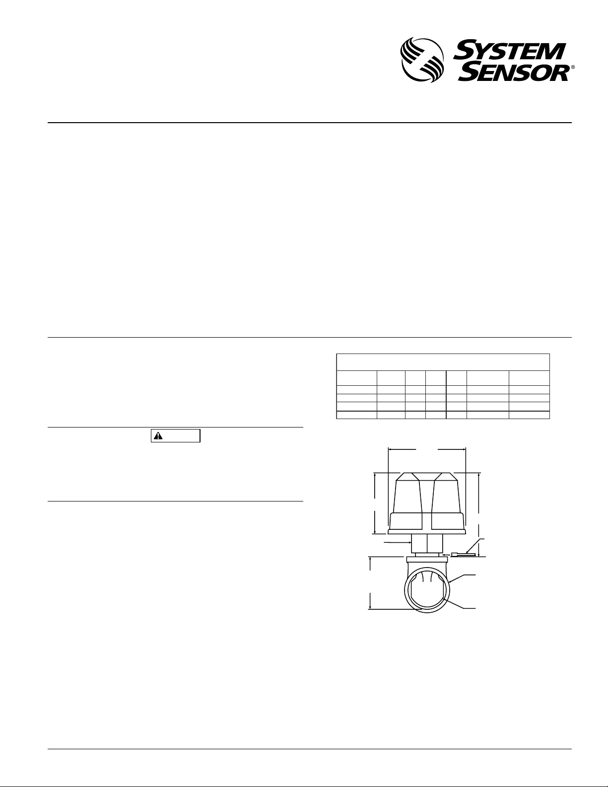
Figure 1. Mounting dimensions:
A78-1939-01
Specifications
Contact Ratings: 0.6 A @ 125 VAC; 2 A @ 30 VDC
Triggering Threshold Bandwidth
(Flow Rate): 4–10 GPM
Static Pressure Rating: 250 PSI (Max.)
Dimensions, Installed:
AFDT– 4
5
⁄16″H × 33⁄4″W × 63⁄4″D
AFDTH– 4
5
⁄16″H × 39⁄16″W × 63⁄4″D
Operating Temperature Range: 32°F - 120°F (0°C - 49°C)
Shipping Weight: 2.6 lbs.
Enclosure Rating:
AFDT– NEMA Type 4, as tested by
Underwriters Laboratories, Inc.
(U.L.)
AFDTH– Indoor use only, as tested by U.L.
Voltage Range: 8.4–35 V (DC–FWR); 108–132 VAC
Power Requirements: 300 µA at 12 or 24 V (DC–FWR);
400 µA at 120 VAC
U.S. Patent Number: 3,845,259; 6,084,521; 6,275,160
D770-34-00 1 I56-1621-004R
AFDT/AFDTH Accuflow™
Vane-type Waterflow Detectors
with Solid State Retard
INSTALLATION AND MAINTENANCE INSTRUCTIONS
3825 Ohio Avenue, St. Charles, Illinois 60174
1-800-SENSOR2, FAX: 630-377-6495
www.systemsensor.com
Important
Please Read Carefully And Save
This instruction manual contains important information about the
installation and operation of waterflow detectors. Purchasers who
install waterflow detectors for use by others must leave this manual or a copy of it with the user. Read all instructions carefully
before beginning.
Use vane-type waterflow detectors in wet-pipe systems only. DO
NOT USE IN DRY-PIPE, DELUGE, OR PRE-ACTION SYSTEMS. The
sudden inrush of water in such systems may break the vane off or
damage the mechanism. Do not use in potentially explosive
atmospheres. Do not leave unused wires exposed.
Principles Of Operation
Vane-type waterflow detectors mount to water filled pipes in
sprinkler systems. Water flow in the pipe deflects a vane.
Deflection of the vane produces a switched output, usually after
a specified delay.
All AFDTs have a controlled delay mechanism. Delays are noncumulative; they reset if the flow of water stops before the entire
delay has elapsed. All detectors will activate on a sustained flow
of water greater than 10 gallons per minute (gpm) but will not
activate if the flow rate is less than 4 gpm.
Compatible Pipe Tees/Risers
The AFDT and AFDTH fit 1″ to 1
1
⁄2″ NPT threaded ferrous and
brass, 1″ to 2″ sweat brass, 1
1
⁄2″ polybutylene plastic and 1″ cpvc
plastic tees having a 1″ threaded NPT branch (see Figure 1 and
chart for recommended tee depths). For 2″ cast and malleable
threaded tees use 2″ paddle ( P02-0023-000) provided.
CAUTION
Installation Guidelines
Before installing any waterflow alarm device, be thoroughly
familiar with:
NFPA 72: National Fire Alarm Code
NFPA 13: Installation of Sprinkler Systems
NFPA 13D: Standard for 1 and 2 Family Dwellings and
Manufactured Homes
NFPA 13R: Standard for Residential Occupancies up to and
including Four Stories in Height
NFPA 25: Inspection, Testing, and Maintenance of Water-
based Fire Protection Systems
The AFDTH can be installed between 2X4 stud wall construction.
Panel Compatibility:
The AFD waterflow indicators may receive power and operate on
a two-wire initiating zone of a fire alarm control panel. When
determining compatibility of these devices, the standby operating
voltage of the control panel must be between 8.5 and 35 volts. In
the standby mode, the AFD draws a maximum current of 0.3 mA.
In alarm, the AFD acts as a short across the initiating zone (similar to a manual fire box). For two wire conventional fire alarm
control panels, not more than 5 waterflow indicators may be
connected to a single initiating zone. The maximum retard/reset
time of the waterflow indicator plus the initiating zone shall not
exceed 90 seconds.
For two wire addressable control panels, the number of waterflow indicators connected to the panel’s signaling line circuit
shall be limited only by the circuit’s current capacity.
Approximate Tee Depth Requirements
Tee Depth Threaded Sweat Poly B CPVC
1 × 1 × 1″
11/4 × 11/4 × 1″
11/2 × 11/2 × 1″
2 × 2 × 1"
21/8″
21/2″
23/4″
1
3
/4″
3
Tee Adapter
Tee Depth
Refer to
Tee Depth
Table
(See Figure 1)
13/4″ N/A 21/4″
1
/6″ N/A
2
21/4″
23/4″
33/4
(AFDT)
3
(AFDTH)
N/A
21/2″
N/A
N/AN/A
9
/16
CPVC/Spears/
Victaulic
15
2
/32″ 213/16″
N/A
N/A
5
/16
4
Gage (End of Paddle Tree)
Must Fit Between Top of
Tee and Bottom of Flange
Tee Fitting
Plastic Vane
CPVC/Central
N/A
N/A
N/AN/A
Page 2
Also, follow other applicable NFPA standards, local codes and the
requirements of the authority having jurisdiction.
NOTE: Installation methods other than those listed in this
installation manual may prevent the device from reporting
the flow of water in the event the associated sprinkler
system is activated by a fire. System Sensor is not
responsible for devices that have been improperly
installed, tested, or maintained.
1. Mount the detector where there is adequate clearance for
installation and removal and a clear view of it for inspection.
See Figure 1 for mounting dimensions.
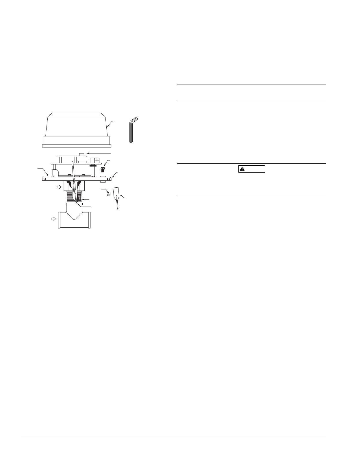
Figure 2. Assembly diagram:
height gage (located at end of paddle tree) to ensure proper
depth of detector on tee fitting. See Figure 1. Height gage must
fit between top of tee fitting and under side of hex tee adapter.
A gap between gage and tee adapter is acceptable. When correctly installed, the detector must face in the proper direction
of waterflow and be aligned with the pipe.
4. Remove the metal cover. Move the actuator lever back and
forth to check for binding. If the vane binds, remove the detector and correct the problem before proceeding.
Be sure the direction-of-flow arrow points in the right direction,
otherwise a waterflow condition will go unreported. See Figure 2.
Preoperation
Fill the sprinkler system with water and check for leaks around
the AFDT or AFDTH. If there is a leak, check to see that the fittings are tight. If leak persists, drain the system and remove the
detector (see removal instructions under Maintenance). Check for
damaged threads or cracked fitting. Reinstall the detector and
check again for leaks. Do not proceed until all leaks have been
stopped.
Wiring
High Voltage. Electrocution Hazard. Do not handle live AC wiring or
work on a device to which AC power is applied. Doing so may result
in injury or death.
1. All models have two wires and two sets of terminals.
Relay Wires (W1 & W2 designated on PCB): These wires are
connected to a latching normally open (as in No Flow) relay
contact. They are isolated from all electronics. They will close
and cause a short when water flows and the retard time elapses. They will remain shorted until waterflow stops. Once waterflow stops, these contacts will re-open.
Power Terminals (T2 designated on PCB): This is a TWO
screw terminal block. The Accuflow gets its power from these
terminals. These terminals must have voltage present from the
FACP or other suitable source of power before anything will
work. If no power is present, the Accuflow will not provide
proper alarm signals. These terminals will accept power in any
polarity as well as AC-line power.
Aux Relay Terminals (T1 designated on PCB): This is a
THREE screw terminal block. These terminals are connected to
a latching Form C relay. In no flow conditions, COM is connected to A. When flow is detected COM will disconnect from
A and connect to B. This relay will latch in that state and reset
after water stops flowing.
See Figures 3 - 8 for specific wiring instructions.
2. Adjust Dip Switch to desired time delay. See Figure 11. For Dip
Switch location, see Figure 2.
3. When connected to a listed sprinkler/fire alarm control panel,
the initiating circuit must be nonsilenceable.
4. A ground screw is provided with all waterflow detectors. When
grounding is required, clamp wire with screw in hole located
between conduit entrance holes. See Figure 9, page 4.
5. If a second conduit entry is required, remove the knockout
plug using a flat blade screwdriver as shown on Figure 10,
page 4. Strike sharply with a hammer to pierce the wall of the
knockout plug. Move to an adjacent wall section and repeat
until the plug falls out. Make sure that the waterflow detector
is supported adequately during this operation to avoid injury.
NOTE: Power terminals must be connected to FACP or other
non-silenceable initiating circuit.
WARNING
D770-34-00 2 I56-1621-004R
A78-2134-05
2. Locate the detector 6 to 7 feet above the floor to protect from
potential damage.
3. On horizontal runs, position the detector on top of the pipe or
on the side of it. Do not mount it upside down because condensation may collect in the housing and impair the operation
of the detector. For vertical flow applications, mount detector
on pipe where upflow conditions exist. Failure to do so may
prevent unit from operating properly.
4. Mount detector at least 6 inches from a fitting which changes
the direction of the water flow, or no closer than 24 inches
from a valve or drain.
5. BE SURE DIRECTION-OF-FLOW ARROW MATCHES ACTUAL
DIRECTION OF FLOW IN THE PIPE.
Mounting Instructions
1. The AFDT and AFDTH waterflow detectors are designed to fit
only the appropriate tee fitting.
NOTE: Leg of tee perpendicular to flow of water must have a 1”
NPT thread. Do not use a reducer to achieve the correct
thread size. Failure to follow this instruction will result
in failure of the detector to report a waterflow condition.
2. AFDT and AFDTH units are shipped without paddles mounted
to the actuator. Select the correct size paddle for the type of tee
being used. Align hole on stem of paddle with hole on actuator lever. Fasten together using a #4-40 x 1/4” fillister head
screw supplied in bag assembly. See Figure 2. Use only the
screw provided with the unit. Drive screw head through hole
in paddle until it seats to actuator lever surface. No washer is
required. For paddle replacement refer to Maintenance section.
3. Carefully roll the vane opposite the direction of flow and insert
through tee. Thread detector onto tee fitting and tighten with
wrench. Use of thread sealant or tape is recommended. Use
COVER
TAMPER PROOF
WRENCH (P/N WFDW)
DIP SWITCH
GROUND
SCREW
GASKET
(AFDT ONLY)
FLOW
WATERFLOW
FILLISTER
HEAD SCREW
1″ NPT THREAD
ACTUATOR
LEVER
(GREEN)
MOUNTING
PLATE
PADDLE
(PADDLE
REPLACEMENT
KIT P/N PRK9)
Page 3

D770-34-00 3 I56-1621-004R
Figure 3. Wiring AFD to bell:
BELLBELL
POWER SOURCE
A
B CO
M
POWER
TERMINALS
AUX RELAY
TERMINALS
Figure 4. (4 Wire Addressable) Wiring the AFD to an
addressable panel using an auxiliary power supply for
power:
Remove the Relay Wires from under the Power Terminals.
Connect these wires to the Addressable Module.
Break wire as shown for
supervision of connection.
DO NOT allow stripped wire
leads to extend beyond
switch housing. Do NOT
loop wires.
Figure 7. Wiring the AFD to a panel and other device:
Leave the Relay Wires installed under the Power Terminals and
connect the panel initiating loop wires as shown below. The AFD
requires power to operate, therefore connect the FACP initiating
loop wires to the Power Terminals and Relay Wires as shown.
EOL
OR NEXT
DEVICE
FACP
POWER SOURCE
BELLBELL
A B COM
POWER
TERMINALS
AUX RELAY
TERMINALS
RELAY
WIRES
Figure 6. Wiring the AFD to a panel:
Leave the Relay wires installed under the Power Terminals and
connect the panel initiating loop wires as shown below.
OR NEXT
DEVICE
POWER
TERMINALS
AUX RELAY
TERMINALS
A B
C
O
M
EOL
FACP
RELAY
WIRES
TO NEXT MODULE
OR EOL
INTELLIGENT
MODULE
FACP
A B COM
POWER
TERMINALS
AUX RELAY
TERMINALS
RELAY
WIRES
Figure 8. (2 Wire Addressable) Wiring the AFD to an
addressable panel using the SLC loop wires for power:
Remove the Relay Wires from under the Power Terminals.
Connect these wires to the Addressable Module.
NOTE: Consult FACP Manufacturer’s Compatibility Guide prior
to installation.
Figure 5. Wiring the AFD using 4 wires. (Aux. Power from
Panel):
Remove the Relay Wires from the Power Terminals. Cut off the
spade lugs from the ends of the Relay Wires. Put wire nuts over
ends of Relay Wires as shown. Use Aux. Relay Terminals to make
connection to panel and next device as shown..
NOTE: To comply with NFPA code, never put more than two
wires in a wire nut.
Relay wires and power terminal wiring must be contained within
either a common enclosure or enclosures within 20 feet of each
other with wiring inside conduit.
CAUTION
AUX. POWER
OUTPUT
INITIATING
LOOP
A B COM
POWER
TERMINALS
AUX RELAY
TERMINALS
RELAY
WIRES
FACP
EOL POWER
SUPERVISION
RELAY (SHOWN
ENERGIZED)
A77-716 12/24V
EOL
AUX.
POWER
OUTPUT
MODULE
SLC
LOOP
A B COM
POWER
TERMINALS
AUX RELAY
TERMINALS
RELAY
WIRES
FACP
MODULE
A B COM
POWER
TERMINALS
AUX RELAY
TERMINALS
RELAY
WIRES
NOTE: PLACE MODULE EOL
RESISTOR ACROSS RELAY
WIRES INSIDE AFD COVER.
NOTE: PLACE MODULE EOL
RESISTOR ACROSS RELAY
WIRES INSIDE AFD COVER.
AFD
ENCLOSURE
AFD
ENCLOSURE
EOL POWER
SUPERVISION
RELAY (SHOWN
ENERGIZED)
A77-716 12/24V
Page 4

Operational Testing
Always notify a central station monitoring waterflow alarms
before repairing, maintaining or testing waterflow alarm devices.
1. Replace the cover and tighten the security screws with the
tamper proof wrench. Store the wrench in a secure place.
2. Open the inspector’s test valve and time how long it takes for
the detector to indicate a flow condition. The detector should
remain activated until the inspector’s test valve is closed. Air
pockets in the sprinkler system may increase the apparent time
delay.
Maintenance
To prevent accidental water damage, control valves should be
shut tightly and the system completely drained before waterflow
detectors are removed or replaced.
Inspect detectors monthly for leaks. Test detectors at least monthly as described under Operational Testing above to insure proper
operation. This device is not designed for use on “dry pipe” systems. Test more often if required by the authority having jurisdiction.
Do not repair or replace any other waterflow detector components
in the field. If any other part of the detector does not perform
properly, replace the entire detector.
Proceed as follows to remove a detector.
1. Drain the pipe.
2. Turn off electrical power to the detector, and then disconnect
wiring.
3. Unscrew AFDT or AFDTH from tee fitting.
4. Lift detector clear off the pipe.
If a vane breaks off in a pipe, find and remove it. Failure to do so
may restrict the proper flow of water to part of the sprinkler system.
CAUTION
Three-Year Limited Warranty
System Sensor warrants its enclosed waterflow detector to be free from defects in
materials and workmanship under normal use and service for a period of three years
from date of manufacture. System Sensor makes no other express warranty for this
waterflow detector. No agent, representative, dealer, or employee of the Company
has the authority to increase or alter the obligations or limitations of this Warranty.
The Company’s obligation of this Warranty shall be limited to the repair or replacement of any part of the waterflow detector which is found to be defective in materials or workmanship under normal use and service during the three year period commencing with the date of manufacture. After phoning System Sensor’s toll free number 800-SENSOR2 (736-7672) for a Return Authorization number, send defective
units postage prepaid to: System Sensor, Repair Department, RA #__________, 3825
Ohio Avenue, St. Charles, IL 60174. Please include a note describing the malfunction
and suspected cause of failure. The Company shall not be obligated to repair or
replace units which are found to be defective because of damage, unreasonable use,
modifications, or alterations occurring after the date of manufacture. In no case shall
the Company be liable for any consequential or incidental damages for breach of this
or any other Warranty, expressed or implied whatsoever, even if the loss or damage
is caused by the Company’s negligence or fault. Some states do not allow the exclusion or limitation of incidental or consequential damages, so the above limitation or
exclusion may not apply to you. This Warranty gives you specific legal rights, and
you may also have other rights which vary from state to state.
The Limitations of Waterflow Alarm Devices
WARNING
1. Waterflow detectors may not work or operate properly if sprinkler piping being
monitored is plugged with pipe scale, mud, stones or other foreign material.
Sprinkler systems should be checked regularly for such blocking material, following the instructions in NFPA Standard 25.
2. Alarms generated by the activation of waterflow detectors may not be received
by a central station if telephone or other communication lines to the detector are
out of service, disabled, or open.
3. Vane-type waterflow detectors have a normal service life of 10-15 years. Hard water
systems, however, may substantially reduce waterflow detector service life.
4. Waterflow detectors are not a substitute for insurance. Building owners should
always insure property and lives being protected by sprinkler systems.
5. If valves controlling the water supply to a sprinkler system are closed, vane-type
waterflow detectors will not work. All valves controlling a sprinkler water supply should be sealed or locked in the normally open position. The normally open
position should be monitored by a sprinkler supervisory switch.
D770-34-00 4 I56-1621-004R
©
2002 System Sensor
Figure 11. Solid State Retard Timing Chart:
ON 123
Caution: Only use the above
timer settings. Timing
settings must not exceed
90 seconds.
Switch 1 Switch 2 Switch 3
Time (sec) (60 sec) (30 sec) (15 sec)
0 OFF OFF OFF
15 OFF OFF ON
30 OFF ON OFF
45 OFF ON ON
60 ON OFF OFF
75 ON OFF ON
90 ON ON OFF
Figure 9. Ground screw location:
Figure 10. Knockout plug removal:
GROUND
SCREW
(GREEN)
MOUNTING
PLATE
Please refer to insert for the Limitations of Fire Alarm Systems
 Loading...