

Page 1
1
© System Sensor 2008 I56-2634-004ENPittway Tecnologica S.r.l, Via Caboto 19/3, 34147 Trieste, Italy
DEUTSCH
ENGLISH
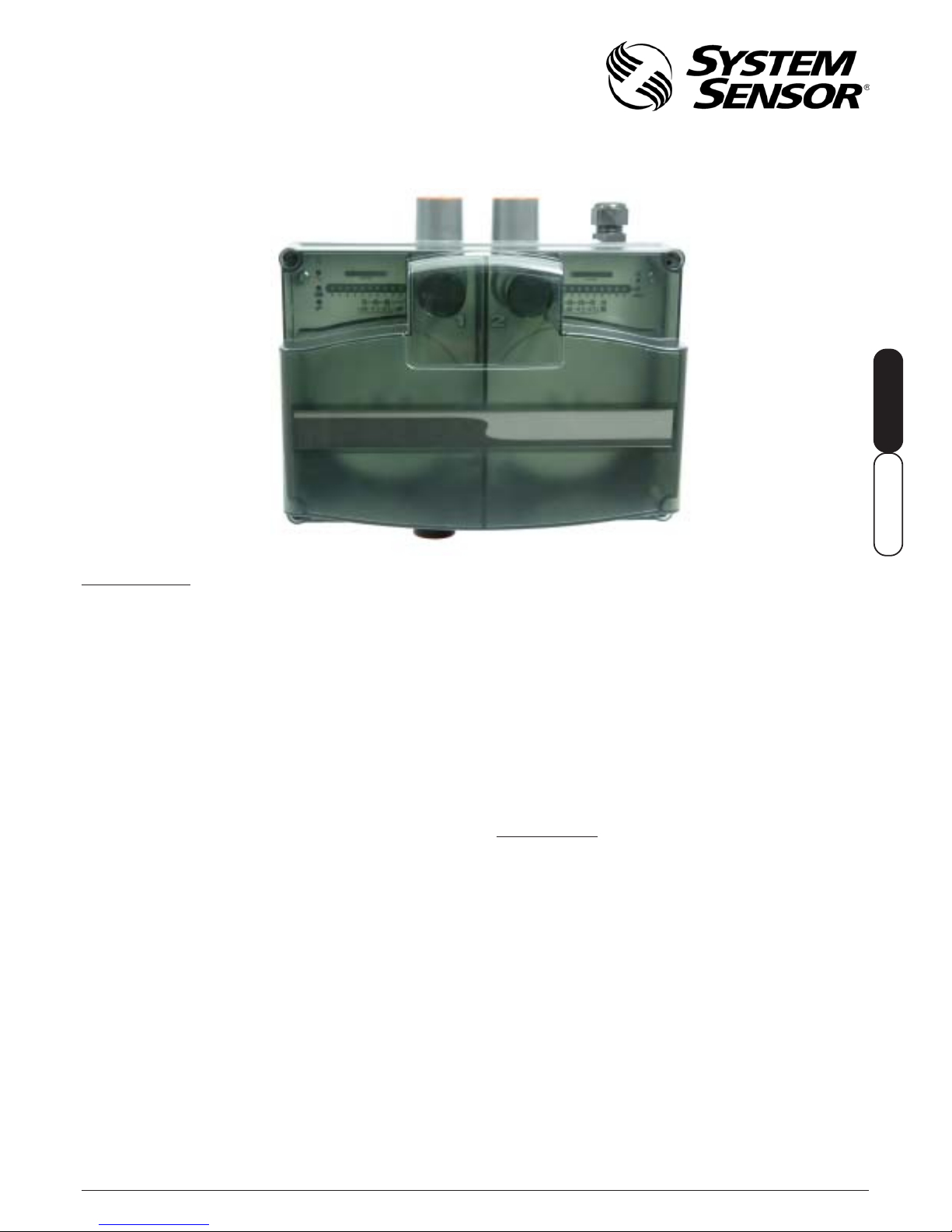
INSTALLATION AND MAINTENANCE INSTRUCTIONS
A300 SERIES ASPIRATED SMOKE DETECTOR
should be monitored using a separate monitor module to
return the fault.
A300E Series smoke detectors are powered by an external
24Vdc power supply .
With the use of an exhaust pipe, the system is IP65 rated,
allowing its use in many harsh environments, and
applications where regular hosing is performed.
CA UTION!
The A300 Series has been independently tested and
certified to CEA4022 and must be installed in strict
compliance with these instructions if the certification
is to be maintained.
SPECIFICATIONS
Number of Sensors: A310E:1 or 2 sensors. A320E: 2 sensors
(order separately, recommended: 7251 sensor).
Internal Filtration: 2 stage dust particle filter
Flow Monitoring: Thermal device, high and low thresholds.
10 element bar graph indication.
Relay fault reporting
Supply Voltage: 24VDC (Nominal) 18-30VDC (12W min)
Supply Current: 120 mA - 500 mA depending on fan speed
setting and supply voltage. Maximum
current 350mA @24VDC with no aspirating
pipe (See table 4 for typical currents/fan
speeds)
Maximum Pipe Length: 1 Chan - 100 metres
2 Chan - 2 x 100 metres
Dependant on sensor type and application
IP rating: IP53 / IP65 optional with exhaust fitted
Operating Temperature: -10°C to 50°C
Operating Humidity: 10 to 95% RH (non-condensing)
Fuse Type/Rating: ‘T’ European sub-miniature (TR5)
1.25 A Anti-surge
INTRODUCTION
There are many instances where aspirated smoke
detectors are specified, but where the very high sensitivity
that is normally inherent in these devices is an
unnecessary expense. The A300E Series Aspirated Smoke
Detector provides the perfect solution.
A300E Series aspirating smoke detectors are available in
single or dual channel formats giving a large monitored area
using sampling holes in the place of point detectors.
The A310E single channel unit has a single detection pipe,
and may be used with one smoke sensor, or two sensors
which can be configured for alarm coincidence at the panel
to simulate a ‘Double Knock’ type operation. (Note: Not
included in VdS appro val).
The A320E unit is equipped with two detection pipe
channels and should be fitted with one sensor for each
channel and can thus cover a greater area than the A310E.
A high performance aspirator and flow monitoring circuit
ensure a constant, monitored flow level which can be
displayed on a 10 element bar graph with adjustments for
high and low flow thresholds.
The A300E Series units incorporate in-line air filters to
remove dust particles from the air samples.
A300E Series Aspirating smoke detectors provide closed
loop sampling whereby the exhausted air can be
completely returned to the sampled area making them
particularly suitable for prison cells.
A300E Series Aspirating smoke detectors use one or two
standard intelligent or conventional smoke sensors which
communicate their status directly with the control panel
(Recommended: 7251 Laser Sensor). The A300E monitors
its own systems and uses relay contacts to signal system
faults. If using an intelligent fire system, these contacts
Page 2
2D200-41-00
Pittway Tecnologica S.r.l, Via Caboto 19/3, 34147 Trieste, Italy
Pipe Specification
For full details of pipe installation please see the appendix
at the back of this manual.
Smoke tests should be performed before planning and
installing the pipe network.
Material
For CEA4022 compliance, the pipe should be red ABS to
EN 50086-1 (Crush 1, Impact 1, Temp 33).
Dimensions
Metric: 25.0mmOD - 21mmID;
Imperial: 3/4"BSP (26.7mmOD - 20mmID)
Note: Both metric and imperial sizes will fit into the unit.
Lengths may be cut as required, and joined by permanent
sockets, removable socket unions or solvent welded.
The A300 inlet port is tapered to allow a push fit of the
sampling pipe. The pipe should be cut squarely to ensure a
good, airtight seal. Solvent adhesive should not be used
for this joint.
Fixings
The means of fixing the pipe to the structure will depend on
site conditions. The normal methods are pipe clips, saddle
clamps or even tie wraps. Fixing centres are typically 1.5m
apart.
Holes
The sampling pipe is perforated with sampling holes at
design spacing. These are typically 3mm and can either be
pre-drilled or drilled in situ. Care should be taken to avoid
swarf entering the pipe. It is always good practice to blow
compressed air through the pipe after drilling to clear any
debris before final connection to the equipment. In standard
configuration, with pipe hanging from ceiling, the holes will
be placed underneath, so the smoke can easily rise up into
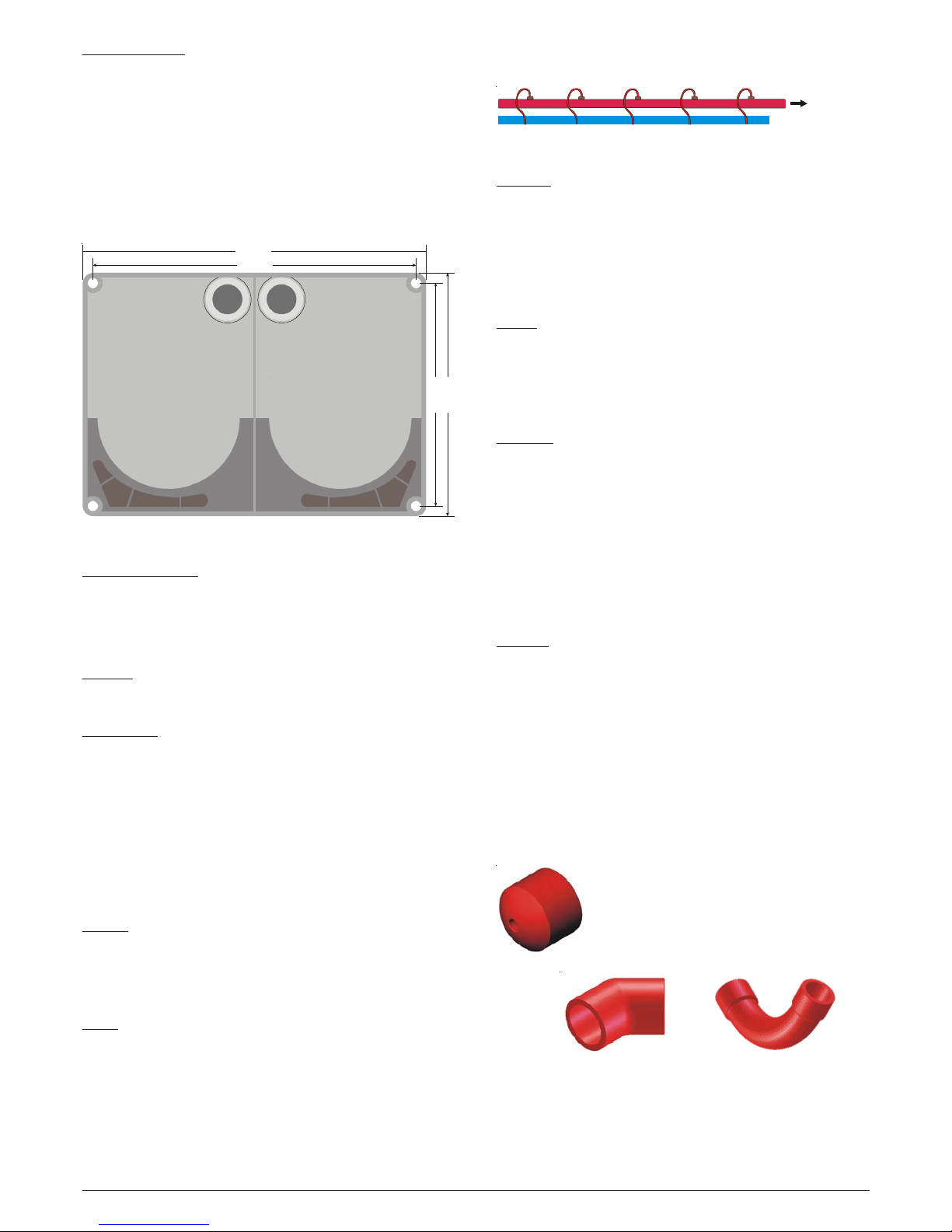
Figure 1: A300E Series Mounting Hole Centres
INSTALLATION
A300E Series Installation
The front cover of the A300 will need to be removed to
secure the unit permanently in place. This is done using
the special key that is supplied, which fits into the screw
hole in each corner of the unit. Please keep the key in a
safe place.
The A300E should be secured to a suitable surface through
the 4 corner fixing points as shown below using suitable
fasteners, for example no.6 wood screws.
Figure 2: Capillary Tube Sample Holes
End Cap
The end of the pipe should be terminated with an end cap,
having a central hole typically 6mm in diameter.
If the end cap is not used, then practically no air will be
drawn through the side holes.
Without a hole in the end cap the contributions from the
side holes will tend to be very unbalanced.
Bends
Bends are either 45 or 90 degrees. For the 90-degree bends
it is very important that slow radii are used and not a sharp
elbow , as this will introduce unacceptable pressure losses ,
and significantly increase the response times from holes
beyond the bend.
T Pieces
A T joint can be used on pipes to produce 2 branches. It is
recommended that the total number of holes in a resulting
pipe system is no more than the number of holes estimated
for a single pipe design. For example, if a single 100M pipe
can have up to 18 holes, 2 branches can have up to 9 holes
each. It is important that the branches have a balanced
design - that is, they should be approximately equal in
length and number/size of holes). For further information,
please see the maximum pipe length/hole size data in Table
6 and the T Piece e xample shown later in the manual.
Exhaust
In most installations the exhaust should be left open, but
there are some circumstances when it may be necessary
to connect a pipe to the exhaust port to divert the exhaust
away from the location of the unit; For example to reduce
noise, reduce risk of interference/deliberate obstruction,
improved environmental protection etc.
Pipe of the same specification as the sample runs should
be used and its length limited to a maximum of 10m to avoid
significant reduction in the airflow. Care should be taken to
position the new exhaust outlet where it cannot be
accidentally or deliberately blocked.
A320E Installation
Where the two pipe A320E unit is used, it is important that
the air flow through the two pipes is balanced otherwise the
responses of the two sensors may be affected.
Figure 3: Pipe Accessories
45° AND 90° PIPE BENDS
END CAP
242 mm
1
6
7
m
m
1
8
4
m
m
259 mm
To A300 E
Ceiling
the hole. Capillary tubes can also be used with the holes as
in figure 2.
Page 3
3
© System Sensor 2008 I56-2634-004ENPittway Tecnologica S.r.l, Via Caboto 19/3, 34147 Trieste, Italy
DEUTSCH
ENGLISH
A300E SERIES WIRING
Warning
Before working on the system, notify the proper
authorities that the system is undergoing maintenance
and will be temporarily out of service. Ensure that all
power is removed before opening the A300E unit.
Note: All wiring must be in accordance with local requirements
The A300E connections are accessed by removing the unit
cover using the supplied key, and then carefully lifting the
front display panel away from the A300E housing. The
ribbon cable that connects the front display PCB to the
main PCB may be unplugged if necessary .
The main PCB (See figure 4) includes wiring terminal
blocks for connecting the 24V power supply to the A300E
unit, accessing the fault relay contacts for each channel
and the optional loop connections.
Power Connection
The A300E unit is designed to run from a nominal 24VDC
supply. The supply should be connected to the 2 way
connector on the main circuit board ensuring that the wires
are correctly orientated. It is recommended that the wires
should be a minimum size of 16 x 0.25mm (18AWG), or
larger if the supply is further than 5m from the system.
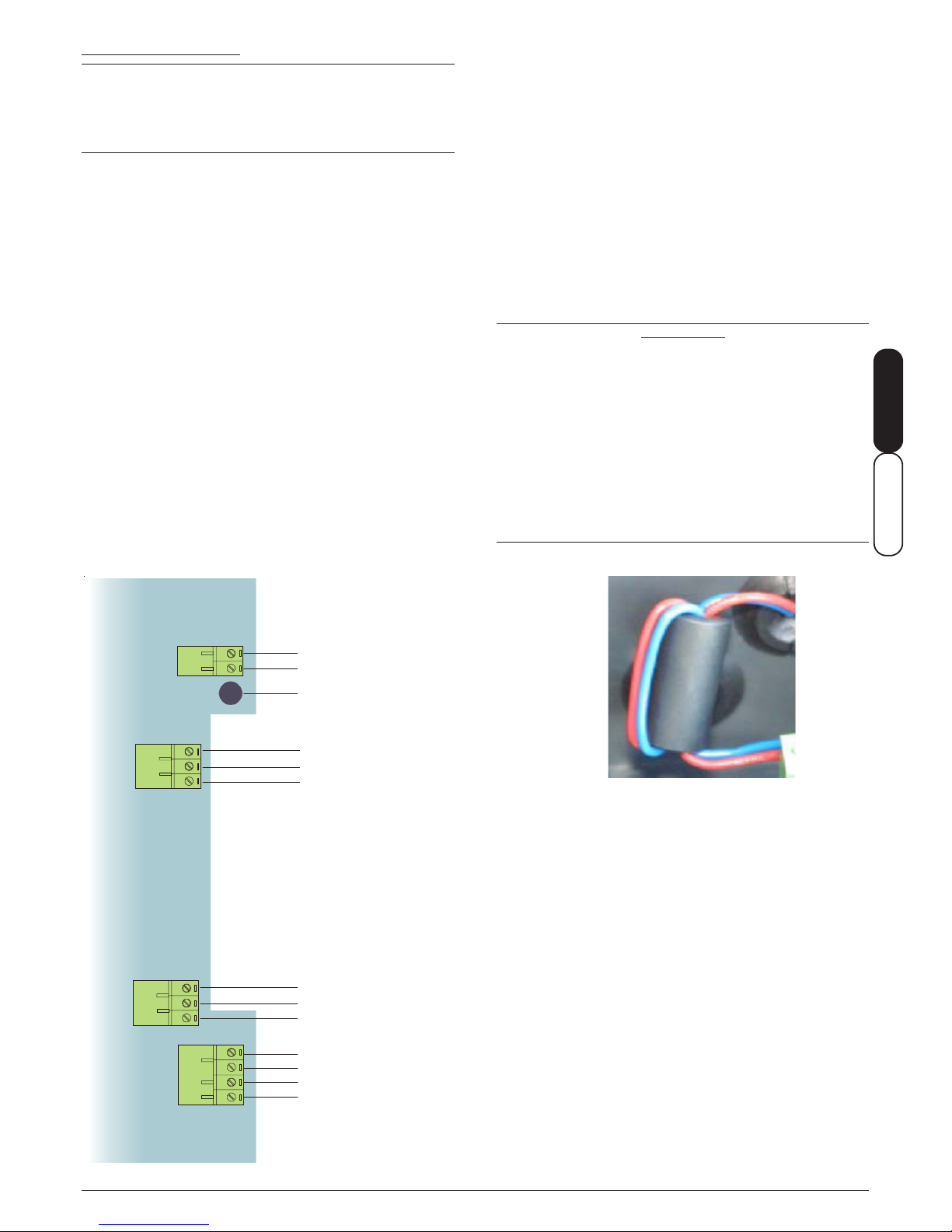
A ferrite core is provided for EMC compliance. This should
be fitted to the supply wiring as shown below.
The current drawn is dependent on the fan speed – see
Table 4 for details.
LOOP OR ZONE CONNECTIONS FROM FIRE
DETECTION CONTROL PANEL
Figure 4: A300E SERIES Terminal La yout
ASPIRATING SYSTEM
CHANNEL 2 FAULT
CONTACTS (A320E DUAL
CHANNEL UNIT ONLY )
NO
COM
NC
NO
COM
NC
EXTERNAL POWER SUPPLY
TO ASPIRATING SYSTEM
ASPIRATING SYSTEM CHANNEL 1 FAULT
CONTACTS (BOTH A310E AND A320E)
+24VDC
0VDC
FUSE
LOOP IN (+)
LOOP IN (-)
LOOP OUT (+)
LOOP OUT (-)
Sensor Connection
The loop terminals are linked via a ribbon cable to the +/terminals mounted on the front display PCB, which
facilitate connection to the sensor bases if required. The
necessary bases (standard base B501 type for 7251
sensors) should be mounted on the front display panel
using the M4 screws provided, with short wires connecting
to the +/- terminals if used.
Loop wiring connections are made to either the pluggable
terminal blocks or directly to sensor bases, both of which
will accept wire sizes from 1mm² to 2.5mm². For best
results, screened cable should be used. Refer to the
control panel instructions for cable type limitations.
Once wiring has been completed, the A300E unit should be
re-assembled in reverse order .
IMPORTANT
The glands on the top of the unit that provide entry for
the cabling must to be sealed to ensure that the only air
entering the unit is coming in through the sample
pipes. all wiring must pass through the cable seals
provided and no additional holes should be made. In
order to pass a cable through a seal it is necessary to
make a small hole in the centre of the seal with a
pointed implement (e.g. small screwdriver) and then
force the cable through the hole into the bo x. The small
hole will expand to accommodate any cable diameter
from 4 to 10mm and then provide an airtight seal.
Figure WF: Ho w to Fit the Ferrite
NO
COM
NC
NO
COM
NC
Page 4
4D200-41-00
Pittway Tecnologica S.r.l, Via Caboto 19/3, 34147 Trieste, Italy
T1 (-)
T1 (-)
T2 (+)
T2 (+)
B501
B501
T1 (-)
T1 (-)
T2 (+)
T2 (+)
B501
B501
(Wiring when
base #2
not fitted)
WIRING CONFIGURA TION
The A310E and A320E may be wired in several different configurations, dependant on the application and information
required. Typical configurations are shown below .
For the single channel A310E, either one or two sensors can be used (to simulate “double knock” type applications).
For the A320E dual channel system, sensor 1 monitors channel 1, and sensor 2 monitors channel 2.
See relevant sensor and module manuals for correct wiring to the device or base.
LOOP (+) IN
LOOP (-) IN
LOOP (+) OUT
LOOP (-) OUT
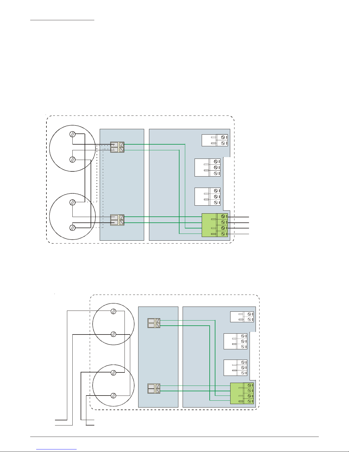
Sensor Arrangement 1.
See figure 5. Two analogue addressable sensors are wired through the aspirating unit. Loop connections are made to the
terminal block on the A300E main PCB.
Note: This configuration can increase the loop impedance by up to one Ohm. If this is lik ely to cause a problem, use Sensor
Arrangement 2 below .
MAIN PCB
DISPLAY PCB
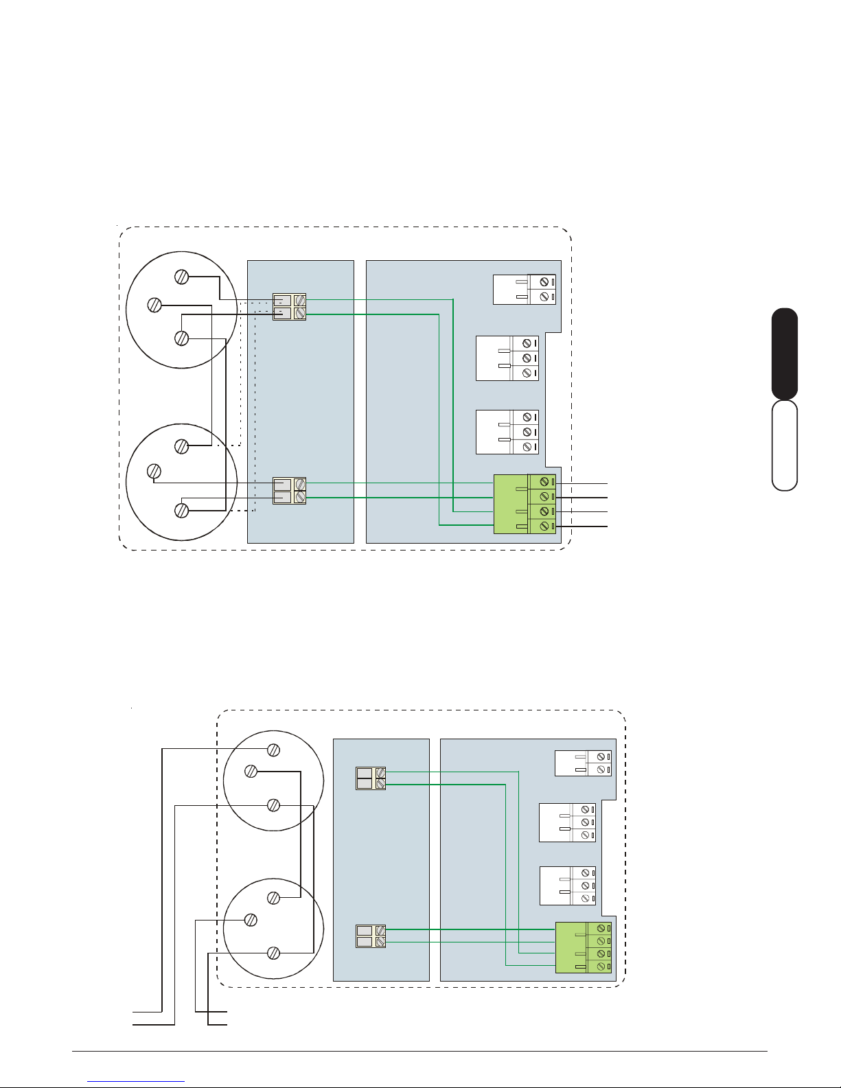
Sensor Arrangement 2.
See Figure 6. The analogue sensors are connected directly to the fire control panel on the loop. The loop wiring is made
directly to the sensor bases.
SENSOR #2
SENSOR #1
A300E ASPIRATING SYSTEM ENCLOSURE
A300E ASPIRATING SYSTEM ENCLOSURE
MAIN PCB
DISPLAY
PCB
LOOP (+)
LOOP (-)
LOOP (+)
LOOP (-)
SENSOR#2
SENSOR#1
Figure 5: Wiring Configuration 1
Figure 6: Wiring Configuration 2
Page 5
5
© System Sensor 2008 I56-2634-004ENPittway Tecnologica S.r.l, Via Caboto 19/3, 34147 Trieste, Italy
DEUTSCH
ENGLISH
T1 (-)
T1 (-)
T5 (+)
T5 (+)
B524IEFT-1
(Wiring when
base #2
not fitted)
T6 (+)
T6 (+)
T1 (-)
T1 (-)
T6 (+)
T5 (+)
T5 (+)
B524IEFT-1
T6 (+)
Using Isolator Bases
The A310E and A320E may be fitted with isolator bases (B524IEFT-1) if required. The basic configurations used on the
previous page are amended below .
Sensor Arrangement 1 with Isolator Bases
See figure 30. Analogue addressable sensors are wired through the aspirating unit. Loop connections are made to the
terminal block on the A300E main PCB.
Figure 30: Wiring Configuration 1 with Isolator Bases
A300E ASPIRATING SYSTEM ENCLOSURE
DISPLAY PCB MAIN PCB
SENSOR#2
SENSOR#1
LOOP (+) IN
LOOP (-) IN
LOOP (+) OUT
LOOP (-) OUT
Sensor Arrangement 2 with Isolator Bases
See Figure 40. The analogue sensors are connected directly to the fire control panel on the loop. The loop wiring is made
directly to the sensor bases.
Figure 40: Wiring Configuration 2 with Isolator Bases
A300E ASPIRATING SYSTEM ENCLOSURE
DISPLAY PCB
MAIN PCB
SENSOR#2
SENSOR#1
LOOP (+)
LOOP (-)
LOOP (+)
LOOP (-)
Page 6

6D200-41-00
Pittway Tecnologica S.r.l, Via Caboto 19/3, 34147 Trieste, Italy
Fault Reporting
Fault monitoring of the A300E unit should be reported back to the panel using one of the suggested input module
arrangements:
For the A310E, a single input M210E module can be used (see Figure 50).
For the A320E, a dual input M220E can be used if separate fault reporting for each channel is required (see Figure 50).
Alternatively, an M210E module can be used if common fault reporting from both channels of the A320E is sufficient within
the system (see Figure 60).
If the wiring and module must remain within the aspirating unit, an M503ME micro module can be used in place of the M210E.
47K R
47K R
4
7
K
R
Figure 50: Suggested Wiring for A310E / A320E Using M210E / M220E Module
A300E ASPIRATING SYSTEM ENCLOSURE
DISPLAY
PCB
MAIN PCB
SENSOR #2
SENSOR #1
EXTERNAL PSU +24V
EXTERNAL PSU 0V
M210E OR
M220E
INPUT
MODULE
(A320E AND
M220E ONLY )
LOOP (+)
LOOP (-)
LOOP (+)
LOOP (-)
Figure 60: Suggested Wiring f or A320E Using M210E Module (Common F ault Reporting)
A300E ASPIRATING SYSTEM ENCLOSURE
MAIN PCB
DISPLAY
PCB
EXTERNAL PSU +24V
EXTERNAL PSU 0V
SENSOR #2
SENSOR #1
LOOP (+)
LOOP (-)
M210E INPUT
MODULE
LOOP (+)
LOOP (-)
Page 7

7
© System Sensor 2008 I56-2634-004ENPittway Tecnologica S.r.l, Via Caboto 19/3, 34147 Trieste, Italy
DEUTSCH
ENGLISH
OK
HI LOOK
HI LO
CODE
0 1 2 3 4 5 6 7 8 9
0 1 2 3 4 5 6 7 8 9
OK HI LO
CODE
0 1 2 3 4 5 6 7 8 9
A310E ASPIRA TING SYSTEM LAYOUT
Figure 7a: Display Functions A310E
POWER ON
(IF FLASHING - VOLTAGE LOW)
GENERAL FAULT
AIRWAY INLET
NOT USED
NOT USED
CODE ENTRY
AIRFLOW SPEED
BAR GRAPH
POSITION FOR
SECOND SENSOR
IF REQURIED
AIRFLOW INDICATOR:
OK, HIGH. LOW
FAN FAULT
A320E ASPIRA TING SYSTEM LAYOUT
Figure 7b: Displa y Functions - Dual Channel V ersion:
POWER, GENERAL FAULT, AND CODE ENTRY INDICATORS ARE COMMON TO BOTH CHANNELS.
UNLOCK
INSTALL
SENSOR
HERE
INSTALL SECOND
SENSOR HERE
AIRFLOW INDICATORS AND AIRFLOW
SPEED BARGRAPH REFER TO THE
CHANNEL IN WHICH THEY ARE LOCATED.
AIRFLOW INDICATOR:
OK, HIGH. LOW
UNLOCK
INSTALL FIRST
SENSOR HERE
GENERAL FAULT
NOT USED
NOT USED
POWER ON
(IF FLASHING -
VOLTAGE LOW)
AIRWAY INLETS
CODE ENTRY
FAN FAULT
Page 8

8D200-41-00
Pittway Tecnologica S.r.l, Via Caboto 19/3, 34147 Trieste, Italy
ASPIRATING SYSTEM SET UP
Refer to figures 7a and 7b to identify LED indicators; figure
8 shows the position of the buttons.
To enter the detector set-up mode, press and hold the
<SELECT> and <CHANGE> keys simultaneously on the
right hand side of the A300E housing until the Code Entry
LED starts flashing.
Access Code
To access the set-up functions, an access code needs to
be entered into the A300E.
T o enter the code , press the <CHANGE> button repeatedly
- the LEDs on the channel 2 (Right Side) Smoke Level /
Airflow Speed bar graph will illuminate in turn. Once the
desired number LED is illuminated, press <SELECT>.
Repeat for each figure in the code.
• The access code is 510
Warning: Ensure that this code is kept secure as it
permits access to the operation functions of the
detector.
Once the third number has been entered, the unlock LED
will illuminate, and will remain illuminated whilst the
aspirating system is in its set-up mode. The system will go
straight into its set up mode, starting from SET FAN
SPEED.
SELECT BUTTON
CHANGE BUTTON
Figure 8: User Functions
T able 1: A310E: Set-Up Pr ocedure.
At each stage, use the <CHANGE KEY> to select the
desired setting. Once the correct value is set press the
<SELECT> key momentarily to accept the setting and step
to the next function. Note that after the final step,
momentarily pressing <SELECT> will wrap back to step one.
A
S
D
Step Mode Indication Function
1. Set Fan Speed “Power On” LED Flashes Sets aspirating system fan speed.
Press <CHANGE> to cycle through fan speed settings for 0 to 9 indicated on LED bar graphs.
Fan speed will change as the settings cycle though.
Press <SELECT> once desired speed is selected to set speed and cycle to next mode
2. Set Bar Graph
Sensitivity
“OK” LED Flashes Press <CHANGE> to set air flow sensitivity as indicated on bar graph.
Press <SELECT> once desired sensitivity is selected to accept and cycle to next mode
3. Set High air flow
limit
“Hi” LED flashes Press <CHANGE> to set upper air flow limit as indicated on bar graph.
Press <SELECT> once desired high air flow limit is selected to accept and cycle to next mode
4. Set Low air flow
limit
“Lo” LED flashes Press <CHANGE> to set lower air flow limit as indicated on bar graph.
Press <SELECT> once desired low air flow limit is selected to accept and cycle to next mode
5. Set Flow Delay ‘Hi/Lo Flow’ LED’s both
flash
Press <CHANGE> to set required delay on Bar Graph (see Table 7)
Press <SELECT> once the desired Flow Delay is selected to accept and cycle to next mode
6. Calibrate Flow
Sensors
Fan Fault LED flashes
then
Power On and Fan Fault
Flash
Once the Fan Fault LED is illuminated, press and hold the <CHANGE> key until all LEDs are
extinguished and the fan stops. After a few seconds, the “Power On”, “Fan Fault” and
“Unlock” LEDs start flashing. The fan remains off to calibrate zero flow. After a few seconds,
the fan turns on to calibrate normal flow. On completion of calibration, the unit exits the setup
mode, and the airflow is displayed.
Note: Should any change be made to the pipework, or any
fan adjustment made, then it is necessary to re-calibrate
the fan sensors as in step 5 of table 1, or step 8 of table 2,
as relevant.
Bar Graph Displays
Once the set-up mode has been exited, the current airflow
levels are displayed on the cumulative bar graph display;
the High and Low flow limits are also shown.
SET-UP NOTES
The Fan Speed, Flow Limits and Flow Sensitivity need to
be set for each installation prior to Flow Calibration and
testing. It is not possible to provide the settings for all
possible installations but the following guidelines should
assist in the commissioning of the unit.
The current stage in the set-up is indicated by LED
indicators on the detector fascia as described in table 1.
To exit from setup at any point, press and hold the
<SELECT> key. If no button is pressed f or one minute, the
detector will automatically exit the setup mode.
Setup functions are displayed sequentially as in tables 1
and 2.
Page 9

9
© System Sensor 2008 I56-2634-004ENPittway Tecnologica S.r.l, Via Caboto 19/3, 34147 Trieste, Italy
DEUTSCH
ENGLISH
Fan Speed
The Fan Speed should be set as high as possibleto achie ve
the fastest transport time from the sampling point to the
sensors, this is especially important for longer pipe lengths
and for installations that must conform to the requirements
of CEA4022. There is, however, a balance to be achieved
between performance and the unit’s power requirements,
and reference should be made to the current consumption
figures in the specifications prior to setting this value. F an
speeds of 3 and below should not be used for standard
configurations.
Flow Sensitivity
This setting determines the responsiveness of the system
in reporting blocked sampling points or broken pipes . The
number of sampling points and fan speed are the main
factors to consider for this setting.
T able 2: A320E: Set-Up Pr ocedure.
Table 3 shows typical settings for a variety of standard fan
speed/hole quantity combinations. Other speed/hole
combinations should be verified by testing during
commissioning.
Flow Delay
An increase/decrease in flow above/below the FLOW
HIGH/FLOW LOW limits will result in a FLOW FAULT after
a delay of approximately 15s. Once the flow is returned to a
normal level, the fault condition will be cleared within about
2s. These are the factory set default values.
In environments where the sampled airflow may be
affected by sudden temperature/pressure changes or there
is a risk of physical interference with the sampling point
(e.g. prison cell applications), it may be necessary to
increase the delay between the flow going out of limits and
signalling a FLOW F AUL T condition. Delay values of up to
270s before signalling a fault are available when setting up
the detector.
Step Mode Indication Function
1. Set Fan Speed “Power On” LED Flashes Sets aspirating system fan speed.
Press <CHANGE> to cycle through fan speed settings for 0 to 9 indicated on LED bar graphs.
Fan speed will change as the settings cycle though.
Press <SELECT> once desired speed is selected to set speed and cycle to next mode
2. Set Channel 1 Bar
Graph Sensitivity
Channel 1 “OK” LED
Flashes
Press <CHANGE> to set air flow sensitivity as indicated on Channel 1 bar graph.
Press <SELECT> once desired sensitivity is selected to accept and cycle to next mode
3. Set Channel 2 Bar
Graph Sensitivity
Channel 2 “OK” LED
Flashes
Press <CHANGE> to set air flow sensitivity as indicated on Channel 2 bar graph.
Press <SELECT> once desired sensitivity is selected to accept and cycle to next mode
4. Set Channel 1
High air flow limit
Channel 1 “Hi” LED flashes Press <CHANGE> to set upper air flow limit as indicated on Channel 1 bar graph.
Press <SELECT> once desired high air flow limit is selected to accept and cycle to next mode
5. Set Channel 1
Low air flow limit
Channel 1 “Lo” LED
flashes
Press <CHANGE> to set lower air flow limit as indicated on Channel 1 bar graph.
Press <SELECT> once desired low air flow limit is selected to accept and cycle to next mode
6. Set Channel 2
High air flow limit
Channel 2 “Hi” LED flashes Press <CHANGE> to set upper air flow limit as indicated on Channel 2 bar graph.
Press <SELECT> once desired high air flow limit is selected to accept and cycle to next mode
7. Set Channel 2
Low air flow limit
Channel 2 “Lo” LED
flashes
Press <CHANGE> to set lower air flow limit as indicated on Channel 2 bar graph.
Press <SELECT> once desired low air flow limit is selected to accept and cycle to next mode
8. Set Flow Delay ‘Hi/Lo Flow’ LED’s both
flash
Press <CHANGE> to set required delay on Bar Graph (see Table 7). Note that both
channels will have the same setting.
Press <SELECT> once the desired Flow Delay is selected to accept and cycle to next mode
9. Calibrate Flow
Sensors
Fan Fault LED flashes
then
Power On and Fan Fault
Flash
Once the Fan Fault LED is illuminated, press and hold the <CHANGE> key until all LEDs are
extinguished and the fan stops. After a few seconds, the “Power On”, “Fan Fault” and
“Unlock” LEDs start flashing. The fan remains off to calibrate zero flow. After a few seconds,
the fan turns on to calibrate normal flow. On completion of calibration, the unit exits the setup
mode, and the airflow is displayed.
Tab le 7: Flow Delay Settings
BARGRAPH LED FLOW INTO FAULT DELAY FLOW OUT OF FAULT DELAY
(Seconds) (Seconds)
0* 15 2
130 18
260 18
390 18
4 120 18
5 150 18
6 180 18
7 210 18
8 240 18
9 270 18
*Factory default setting Note: all timings are approximate
Page 10

10D200-41-00
Pittway Tecnologica S.r.l, Via Caboto 19/3, 34147 Trieste, Italy
TESTING
Testing should only be carried out by qualified
personnel. Before undertaking any testing ensure that
the proper authorities have been informed, and if
necessary, that the unit has been isolated from the fire
control panel to prevent unwanted alarms.
Sensor Testing
With the unit powered up and the top cover removed
the sensors can be tested for functionality using methods
described by the manufacturer (for example aerosol spray
or magnet test).
System Testing
Alarm: The installed system must be checked with the top
cover securely fitted. As a minimum, smoke should be
introduced to the furthest sampling point from the A300E
unit on each branch of the pipe. The choice of smoke
source is dependant on the installation but in all cases the
smoke must be present for the duration of the test –
aerosol sprays for point detectors DO NOT work on
aspirated systems.
If it is possible to get close to the sampling point then a
basic, functional check can be carried out with smoke
matches or lighted taper etc. But for measurable
performance tests then refer to Appendix A of the FIA Code
of Practice for Aspirating Systems to select the
appropriate test for the installation.
Fault: Simulate a fault on the A300E unit (for example,
remove the power) and check that a fault is signalled at the
fire panel.
MAINTAINANCE
With normal use, the filter elements will eventually become
contaminated with dust particles, impeding airflow. It is
recommended that it be changed every six months.
To change the filter :
1. Unscrew the top cover
2. Lift out the foam filter elements from its housing
3. Fit a new filter kit so that it lies flush with the top of its
housing
4. Replace the top cover
5. Test the unit as described above.
IMPORTANT
To ensure maximum efficiency and longevity of the filter,
when fitting the replacement filter element kit, the Coarse
filter needs to be fitted first into the pipe.
ACCESSORIES
The following accessories are available to order:
Model Number Product
02-FL50 Replacement Filter Element Kit
20-LA0015 Replacement Key to Open Detector
Table 5: Problem Solving
T able 4: A300E Current Consumption
Fan Speed Current mA
Bargraph Value
0110
1 120
2 130
3 150
4 170
5 190
6 220
7 235
8 265
9 300
T able 3: Typical Flow Sensitivity Settings
PIPE SETUP RECOMMENDED FLOW
(all 50m lengths unless otherwise stated) FAN SPEEDS SENSITIVITY
13 x 3mm Sampling Holes, 1 x 6mm End Hole 9 9
8 x 3mm Sampling Holes, 1 x 6mm End Hole 6-9 9
4 x 3mm Sampling Holes, 1 x 6mm End Hole 6-9 7
1 x 5mm Sampling Hole, 1 x 5mm End Hole 6-9 5
1 x 8mm End Hole 5-9 2
1 x 8mm End Hole (10m Pipe) 3-9 1
Problem Possible Solutions
Power light flashing. Ensure supply to external power
connector within limits.
No lights on display. Ensure supply leads correctly
Fan not running orientated. Ensure that FUSE
correctly seated in socket and fuse
not blown.
No lights on display. Ensure ribbon cable fully seated into
Fan running OK. main & display boards.
Flow HI/LO light on Ensure sampling pipes correctly
installed, lid fitted and box fully sealed.
Ensure filters not blocked.
Ensure flow calibration procedure has
been carried out
Flow reading on Bargraph Decrease Flow sensitivity setting
display moves erratically. and re-calibrate air flows
Flow reading on Increase Flow sensitivity setting
Bargraph unresponsive and re-calibrate air flows
to broken/blocked pipes
Sensor(s) unresponsive Ensure sampling pipe installed correctly
to smoke tests and undamaged. Ensure that holes
and pipe length do not exceed limits
for detector. Ensure that
recommended test method is used.
Page 11

11
© System Sensor 2008 I56-2634-004ENPittway Tecnologica S.r.l, Via Caboto 19/3, 34147 Trieste, Italy
DEUTSCH
ENGLISH
Example 2: With Bends :
All pipes are Metric 25mm or Imperial 3/4” (27.6mm). All sample
holes are 3mm, with 6mm end hole.
* Estimated Values
ASPIRATING SYSTEM CONFIGURATION
Set out below are some examples of maximum length pipe
configurations that can be used with an A300 unit fitted with
the 7251 sensor. It should be possible to adapt these
examples for shorter pipe run systems; however some
specific applications will have specific considerations that
must be taken into account, and local standards may also
apply.
The default size for sample holes is 3mm, and the end hole
is 6mm. Ensure that no hole is less than 100mm from a
bend or ‘T’ piece
Table 6 shows the maximum allowable pipe lengths for
CEA 4022 compliance. In the examples shown below,
which fulfill the requirements of this table, the fire alarm
threshold, set at the control panel, should be at the 7251
laser sensor sensitivity level 1 (most sensitive).
For short to mid range application, it is recommended that
the fan speed for the A300E is kept at a default setting of 5
(this will be suitable in many circumstances). The primary
effect of changing the fan speed will be to increase or
decrease the transport time.
Default settings are programmed into the detector for the
high and low flow limits. It should not normally be
necessary to change these settings.
NOTE
If using a sensor other than the 7251 Laser, see section 3.1
Sensors Certified for use with the A300 in the
Appendices.
Tab le 6: A300E Series Pipe Installation Limits
The following figures apply to System Sensor A310E / A320E
detectors fitted with 7251 sensors
A310E Single Channel System
Example 1:
Aspirating
Smoke
Detector
25mm Pipe Diameter with 3mm Sampling Holes
Heigh t From
Ground 1.5 m
Riser Height
1.0 m
Ceiling Height
2.5 m
Pipe Lengt h
(Incl uding Riser
and Bends)
100 m
First Hole 4.0 m from Riser
6mm End Hole
46.5m
42.5m
10m
Top View
(9 Holes)
(8 Holes)
Aspirating
Smoke
Detector
25mm Pipe Diameter with 3mm Sampling Holes
Height Fro m
Ground 1.5 m
6mm
End Hole
Riser Height
1.0 m
Ceiling Height
2.5 m
Pipe Length
(Including Riser)
100 m
First Hole 4.0 m from Riser
DETECTOR A310E A320E
SENSITIVITY ALARM LEVEL 1 1
(set at the panel)
FAN SPEED 9 9
SINGLE PIPE PER INLET -
Length (Per Pipe/Inlet) Metres 1 0 0 10 0
Max Number of Holes (Per Pipe) 18 1 8
SINGLE ‘T’ (2 PIPES) PER INLET Max Length (Per Pipe) Metres 1 0 0 50*
Max Number of Holes (Per Pipe) 9 6*
Pipe No. Hole Fan Alarm
Length of 3mm Spacing Speed Level
(m) Holes (m)
100 18 5.3 9 1
Pipe No. Hole Fan Alarm
Length of 3mm Spacing Speed Level
(m) Holes (m)
100 17 5.25 9 1
Page 12

12D200-41-00
Pittway Tecnologica S.r.l, Via Caboto 19/3, 34147 Trieste, Italy
A320E Dual Channel System
Example 1:
Example 2: With Bends :
Using T Pieces
Note 1: It is important that the airflow through the 2 branches is balanced,
so each branch will need to be of a similar length and number of holes.
Note 2: Using more than one T piece on each channel has not been
tested and therefore cannot be recommended.
Example 1: 1 Channel
Aspirating
Smoke
Detector
Pipe Length (Including Riser and Bends) 2 x 100 m
Ceiling Height
2.5 m
Height From
Ground 1 .5 m
Riser Height
1.0 m
25mm Pipe Diameter with 3mm Sampling Holes
6mm End Hole
Top V i e w
5 m
5 m
4 m
First Hole 9 m from Riser
Pipe Length to
Bend 94 m
Example 2: 2 Channel
Aspiratin
g
Smoke
Detector
6mm
End Hole
Pipe Len
g
th
(Includin
g
Riser)
2 x 100 m
Ceiling Height
2.5 m
Height From
Ground 1. 5 m
Riser Height
1.0 m
25mm Pipe Diameter with 3mm Sampling Holes
First Hole 4.0 m from Riser
Pipe No. Hole Fan Alarm
Length of 3mm Spacing Speed Level
(m) Holes (m)
2 x 100 2 x 18 5.3 9 1
Pipe No. Hole Fan Alarm
Length of 3mm Spacing Speed Level
(m) Holes (m)
2 x 100 2 x 18 5 9 1
Aspiratin
g
Smoke
Detector
6mm
End Hole
Pipe Lengths
(Includin
g
Riser)
Up to 100 m
Ceiling H e ig h t
2.5 m
Height From
Ground 1.5 m
Riser Height
1.0 m
25mm Pipe Diameter with 3mm Sampling Holes - 1 Channel with T-Piece
5 m
First Hole 5 m from Riser
6mm End Hole
Pipe No. Hole Fan Alarm
Length of 3mm Spacing Speed Level
(m) Holes (m)
1 x 2 2 x 9 10.5 9 1
x 100
Pipe No. Hole Fan Alarm
Length of 3mm Spacing Speed Level
(m) Holes (m)
2 x 2 2 x 2 5 9 1
x 50 x 6
Aspirating
Smoke
Detector
6mm
End Hole
Pipe Lengths
from bend
34 m
Ceil ing Height
2.5 m
Height From
Ground 1.5 m
Riser Height
1.0 m
25mm Pipe Diameter with 3mm Sampling Holes - 2 Channel with 2 T-Pieces
10 m
First Hole 19 m from Riser
6mm
End Hole
Top View
5 m
4 m from bend to first hole
Dista nce Between
Pipes 10 m
Distance Between
Pipes 10 m
Dista nce Between
Pipes 10 m
10 m
5 m
4 m from bend
to first hole
Pipe Lengths
from bend
34 m
Page 13

13
© System Sensor 2008 I56-2634-004ENPittway Tecnologica S.r.l, Via Caboto 19/3, 34147 Trieste, Italy
DEUTSCH
ENGLISH
APPENDICES
Detailed here is information to assist in the set-up of the air-sampling
system, including:
1. Basic Principals of Aspirating Systems
2. Guide to Available Pipe Parts
The pipe network is just as important as the detector itself in providing
a means of obtaining a reliable and continuous sample of air to be
monitored.
The pipework for air-sampling systems can vary greatly depending on
the particular application. The following are guidelines that can be
applied to any wide-bore systems. Please remember that these are
general guidelines only. For each specific installation the local
standards and codes of practice should be adhered to. Guidance on
the design of systems is given in BS 5839, BS 6266 and/or FIA Code of
Practice for Aspirating Detection Systems.
1. Basic Principals
Figure 1.3.1 Smoke Dilution
Figure 1.1 Pipe System Operation
1.1 Smoke T ests
IMPORTA NT
It is strongly recommended that, before designing the pipe-work
system, smoke tests be undertaken in order to show the
patterns of air movement within the areas to be protected. This is
particularly important in rooms with air-handling equipment. In
all cases the aim must be to place the sampling pipes at the
position the smoke is most likely to reach.
Smoke boxes or smoke matches can be used to establish air
movement within the protected area, from which the best place to
locate the pipes can be discovered, as well as where to place the
sampling holes in the pipe.
If air handling equipment is present in the environment, consideration
must be given to all the variable settings that are available (for
example, if it is switched on or off, or if an air conditioning unit has a
directional wave facility).
1.2 Response Times
This is the transport time taken from when a sample enters a pipe to
when the detector unit enters alarm mode.
Response times should be within reasonable limits. The simplest
method of achieving this is to keep pipe lengths to a minimum. This may
not always be possible but in the following example the benefits of
using more than one pipe in short lengths is demonstrated (this is being
used as a general example only, for any specific installation a proper
calculation will need to be made - This would include the length of the
piping, height of the room,the frequency and size of the sampling holes
etc).
In Figure 1.2.1, a room has a single sampling pipe that provides
detection for the whole room:
Aspirating Unit
containing detector
and fan
Fan draws air down
pipe system for
detector to sample
smoke plume rises and
enters pipe system through
samp ling poin t ho l e s
Figure 1.2.1 Single Sampling Pipe
In Figure 1.2.2, the same room has a two channel sensor, allowing two
sampling pipes:
Figure 1.2.2 Two Sampling Pipes
The system gives the same coverage as it would with one pipe, but the
response time is quicker. The principal shown here is also relevant
when considering the dilution rate. Please see the following section for
details on this.
1.3 Dilution
The response time example does not only show the benefit of shorter
pipes on response times. Dilution is also kept to a minimum by reducing
the length of the pipes. As the name suggests, dilution is the process
of lessening the concentration of smoke particles as the sample is
drawn towards the detector.
For example, if there is a sampling pipe measuring 50 metres and It
has sampling holes every 5 metres, giving 10 sampling holes including
the end cap. It can be assumed in this simplified case that the sampling
holes let in approximately the same amount of air as each other.
A smoke source of 2% obscuration/metre is introduced at the far end
of the pipe. No other smoke is entering any of the other sampling holes.
As the smoke passes each hole, it is added to with clean air. When the
sample reaches the detector it is now at 0.2% obscuration/metre or 1/
10th of its starting density. Therefore if the first alarm threshold is set at
0.2% obs/m, the smoke outside the hole must exceed 2% obs/m to
sound the alarm.
It is the case, therefore, that the longer the pipe and the greater the
number of sampling holes, the more susceptible the system will be to
dilution. It is wise to work on a worst case principle in these situations.
In actuality the calculation of dilution is not as straightforward as above
and more factors are involved. Each system will have different
characteristics meaning precise calculation is extremely complicated.
Issues that will affect the dilution rate include size and number of holes,
T-pieces and elbow joints in the pipe system, diameter of the pipe itself,
and outside elements such as air temperature, pressure and humidity etc.
Let us say that the response time for smoke that
Entered the very end of the pipe was 34 seconds
Smoke
Enters
Here
Smoke
Enters
Here
With two pipes feeding into a 2 channel detector,
the pipe length is approximately halved, and so is
the response time to 18 seconds
Page 14

14D200-41-00
Pittway Tecnologica S.r.l, Via Caboto 19/3, 34147 Trieste, Italy
As seen in the previous section on response times, shorter pipe runs
minimise dilution. In Table 1.3.1 there is a rough guide to varying dilution
rates for wide-bore systems - IMPORTANT: The different
characteristics of each installation must also be taken into account
when assessing the dilution rate. many factors can affect this, as
previously discussed.
Table 1.3.1 General Dilution Rates for Wide-Bore Systems
1.4 Pipe Construction and Sampling Holes
Single channel System Sensor aspirating detectors have a maximum
pipe length of 100 metres.
Dual channel aspirating detectors have a maximum pipe length of 100
metres for each channel. Wherever possible, the pipe lengths for each
channel need to be kept to broadly similar lengths (for example, if
channel 1 has a pipe length of 30 m, channel 2 should be approximately
the same length). Failure to do this can result in slow response times,
thereby negating some of the early warning ability of the system.
System Sensor recommends that ABS piping be used due to its
strength and heat resistant properties. The pipe sections should be
glued together using a suitable ABS glue to avoid separation or leaks.
If a section of pipe is likely to need to be disconnected for some reason
in the future, removable unions should be used instead.
Important: Never glue pipes into the aspirating detector unit itself.
Sampling holes should be 3mm in diameter. The end of the pipe should
be capped and have a hole of 6mm in diameter.
Important: Elbows and bends in the pipe system can affect the
flow of air/smoke through the pipes and should only be used
when necessary.
Capillary Sampling
Short lengths of small diameter flexible pipe may be spurred off from
the main wide-bore pipe. This pipe should have an internal diameter of
no less than 7mm and can be of lengths up to 2 metres. For this a
sampling point assembly should be used (an example is shown below).
Capillary tubes can be used to provide concealed sampling points. If
the sampling points need to be as unobtrusive as possible, the
capillary allows the point to be placed flush to the surface. These are
most commonly used when the main wide-bore pipe runs through a
ceiling void, with capillary sample pipes placed through the false
ceiling.
Note 1: It is recommended to avoid running lengths of pipe with
both standard sampling holes and capillary sampling points on
them as this can unbalance the airflow and slow the response
time from the capillary points.
Note 2: Though British Standard BS 5839-1 states that there
must be a minimum of 25mm between the ceiling and the
sampling point of a detector, because the aspirating system
actually draws air through the sampling points (holes in the
pipework in this case), it can be possible to mount the sampling
points flush with the ceiling providing this will not be
detrimental to the effectiveness of the system to detect fire (see
1.1 Smoke Tests).
1.5 The Design Process
When designing the actual sampling pipe network there are many
factors that need to be considered. The site must be carefully
surveyed and as much information as possible should be gathered.
1.5.1 Requirements
The first consideration is to precisely ascertain the requirements of the
installation. Once these have been decided, the type of situation can be
looked at.
1.5.2 Activities
The types of activities that take place within the space are very
important. A public area of a particular shape could well have different
system requirements to a warehouse of a similar shape.
Other information such as the expected hours of operation, whether
the area is manned or unmanned and whether any pollution or dirty air
is present should also be taken into account.
1.5.3 Physical Characteristics
Once the general installation type has been considered, the physical
characteristics of the space should be looked at.
· Is it a room, void, cabinet or enclosure?
· Are there any floor or ceiling voids and, if so, how are they
divided, are there any ducts, what are these used for and are
there any services already present?
· What are the exact measurements of the space?
· What materials have been used and are there any areas where
the network has to avoid?
· Are there any existing fire protection systems and where are
they situated?
1.5.4 Environmental Conditions
The environment within the space can have a very significant bearing
on which sampling method should be used to protect it. As already
mentioned, the smoke tests are vital in gathering this information. This
can tell you the patterns of air movement, the rate of circulation and
whether the airflow is static at any point. Other considerations include:
· If fresh air is introduced, at what rate and in what quantity?
· Is a reference detector necessary due to pollution?
· What is the temperature and relative humidity and are these
constant or variable?
· Are there any activities that may produce smoke, dust, steam
or flames and how often does this occur?
1.5.5 Risk Assessment
With any installation it is likely that some areas require more protection
than others. This could be because of expensive equipment or a
particularly vulnerable area such as a store for flammable materials.
These more susceptible areas must be considered along with any
structural hazards such as synthetic materials and foams or soft wood
partitioning.
1.5.6 Potential Sites
There are also factors to consider when deciding where to position the
detector unit itself. The main aim when positioning the unit is to tr y to
ensure a balanced system. This means that the pipes should be kept at
similar lengths. It is also important to try and keep response times and
dilution to a minimum.
The unit requires a power supply and access will be required for
maintenance. There may also be aesthetic reasons why a particular
position is not suitable.
1.5.7 Exhaust Pipe
The exhaust pipe on the bottom of the aspirating detector unit can have
piping added should it be required, for example if the air passing
through the detector needs to be returned to its source. Extra piping
can also be used to reduce the noise of the fan if needed.
Page 15

15
© System Sensor 2008 I56-2634-004ENPittway Tecnologica S.r.l, Via Caboto 19/3, 34147 Trieste, Italy
DEUTSCH
ENGLISH
2. Guide to Av ailable Pipe P arts
System Sensor offers the following pipe parts:
2.1 Metric 25mm Pipe Options
Model Number Product Description
02-0001-25 Large Bore Red Pipe 3m Length, 25mm
02-1001-25 Straight Union Large Bore 25mm
02-1002-25 90 deg. Bend Large Bore 25mm
02-1003-25 45 deg. Elbow Large Bore 25mm
02-1005-25 Removable Union Large Bore 25mm
02-1007-25 T-Piece 25mm
02-1006-25 End Cap for Large Bore 25mm
02-FLU2 Filter Unit 25mm With Filter Element
(for Harsh environment)
2.2 Common Accessories
There are a number of accessories that can be used:
Model Number Product Description
02-1008-15 Flush Capilar y Sampling Point
(T Piece & 1.5m Capillary Tube)
For use with false ceilings
02-1009-00 Sampling Point Label (Roll of 100)
02-1010-00 Open Pipe Clip (25mm)
02-1110-00 Closed Pipe Clip (25mm)
02-1011-00 ABS Pipe Adhesive (250ml tin)
25mm Wide
Bore Pipe
Filter Unit
Pipe
Ceiling
Page 16

16D200-41-00
Pittway Tecnologica S.r.l, Via Caboto 19/3, 34147 Trieste, Italy
3. Using Other Sensors with the A300
If the A300 units are to be used with sensors other than the
recommended 7251, please observe the following information:
3.1 Sensors Certified for use with the A300
The following sensors have been independently tested and certified to
CEA 4022 for use in the A300 unit. The table shows the limits which
should not be exceeded if the installation is to conform to this
requirement.
No.12345678910
Dist(m)99.5959085807570656055
Size(mm)3.43.43.43.43.433333
No.11121314151617181920
Dist(m)504540353025201510 5
Size(mm)2.52.52.52.52.522222
SINGLE PIPE VARIABLE HOLE CONFIGURATION
Sensor Model Sensitivity Level Sampling Hole Limits Max Pipe Length (m)
2251EM Standard (2200) 1 x 8mm End 50
2251EM High (1800) 2 x 5mm 50
ECO1003 N/A 2 x 5mm 50
7251 Alarm Level 3 13 x 3mm, 6mm End 100
7251 Alarm Level 1 18 x 3mm, 6mm End 100
7251 Alarm Level 1 20 x Variable Size 100
FSL-751E/
LZR-1M Alarm Level 1 18 x 3mm, 6mm End 100
FSL-751E/
LZR-1M Alarm Level 1 20 x Variable Size 1 00
4. UNUSUAL APPLICATIONS
In these different and variable situations, it is vital to perform smoke
tests to establish the air movements.
4.1 Freezer rooms
Freezer rooms often introduce extra difficulties into the design of a
system. The air temperatures at which the room operates must be
taken into account.
If the aspirating pipe network is inside the cold room the following points
should be noted:
1) The pipes should be suspended (or attached) further away than
usual from the ceiling or wall as these may contract and expand
with large changes in air temperature.
2) Sampling holes should be drilled on the
side of the pipes
to
minimise the risk of blockage owing to ice formation.
3) Vertical pipes running into the room from outside, and areas where
condensation could collect, must be avoided.
Figure 4.1: Typical Freezer Room Example
Heater
Element
Pipe Falls T o wards
Heater
Seal
Stand-Off
300mm Minimum
Holes Drilled in Side of Pipe
Aspirating
Detector
Insulate From W all
Air Return
Freezer Room
Water
Trap
Aspirating Detector and Associated Equipment
Located Outside Freezer Room
Seal
Temperature changes may cause expansion or contraction in the
aspirating pipe. ABS pipe has a linear coefficient of expansion of
around 10-4/°C and large temperature changes can have a significant
effect. These changes typically occur as the system is run to
operational temperature. So the air can easily vary from +18°C at
installation to -35°C in operation, representing a 53°C differential. This
drop applied to a 50m pipe run gives an expected end to end pipe
movement of 265mm. If the design of the system gives no allowance
for such variation in the pipe length, it is advisable to incorporate one or
more simple ‘U’ bends to act as an expansion/contraction point as
shown:
Page 17

17
© System Sensor 2008 I56-2634-004ENPittway Tecnologica S.r.l, Via Caboto 19/3, 34147 Trieste, Italy
DEUTSCH
ENGLISH
4.2: Cold Stores
Cold stores are similar to the freezer rooms with one major difference,
the temperature. The temper ature in a cold store is a lot less than a
freezer and is typically just at or above 0°C.
The pipes should be kept out of the immediate airflow from a chiller unit,
if used, as its air is often significantly colder than the room itself in order
to maintain the correct temperature.
In a cold room application it is not usually necessary to use a heater
element but only a water trap to remove condensation.
4.3: High buildings
Typical examples: Atria; Cathedrals
When designing a system to fit in a very large and high room such as
an atrium or high level warehouse, it is important to consider the
various possibilities. A simple atrium design is shown below, utilising
two pipes. The smoke cloud is shown as an example of how a
stratification layer prevents the pipes at the top of the building from
detecting smoke particles. The height at which the smoke forms a layer
varies depending on temperature and therefore a vertical sampling
pipe is used to cover this. There may be no stratification layer at all if the
air in the room is at a particular temperature, especially if smoke
ventilation is needed.
Figure 4.3: Typical Atrium Example
Sampling Pipes
Sampling Holes
Aspirating
Detector
Smoke Stratification Layer
Figure 4.4.2: High Roof Example 2
Pipes Running Parallel to the Roofline
Max.
10m
Max.
10m
Pipes Run the Length of the Building (Parallel to the Roofline)
Aspirating Detectors
Figure 4.4.1: High Roof Example 1
Pipes Running Across the Width of the Roofline
Aspirating
Detector
Maximum 10m Between
Pipes at the Roof
Pipes Run the Width of the Building (across the Roofline)
The second alternative shows the pipes running in parallel along the
roof. Again to comply with UK requirements the pipes should be a
maximum distance of 10m apart, sample holes in each pipe will be 10m
from each other and the pipe serving the apex should not be further
than 600mm from the top of the roof.
4.5: W arehouses
Warehouses can be considered to be similar to supermarkets except
the same problems that can occur with high buildings need to be taken
into account as well. Vertical sampling points may be needed and the
pipe lengths should be considered carefully to ensure reasonable
response times.
4.4: Supermarkets and Storage Areas
Supermarkets and storage areas require a high level of protection due
to the possible number of people using the space at certain times of the
day and/or due to the value of the goods present.
There are two ways of applying the pipe network. The exact structure
of the roof is likely to determine the better or most appropriate solution.
The pictures below assume a simple room layout.
In one alternative the pipes will follow the contour of the roof. To comply
with UK code of practice BS5839:1, pipes will be placed at a maximum
distance of 10m from each other and sampling holes will also be sited
at a maximum of 10m from each other, with the hole serving the apex
no more than 600mm away from the roof.
 Loading...