

Page 1
INSTALLATION AND MAINTENANCE INSTRUCTIONS
PART NO.
A3008-00
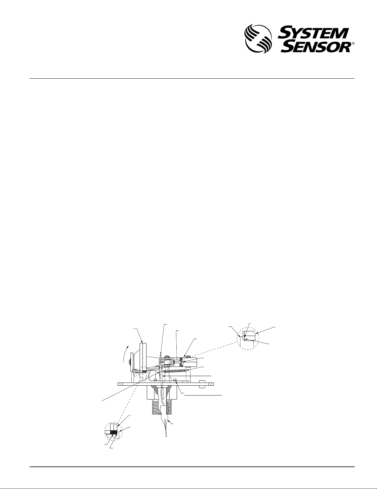
TILT 30∞ TO
REMOVE AND
RE-INSTALL
DELAY
MECHANISM.
TIMER STOP
CUTAWAY
VIEW
RAISED
BOSS
PART NO.
A77-01-02
STOP
SWITCH
ENCLOSURE
VERTICAL
ALIGNMENT
WALL
(BEHIND STOP)
SWITCH ENCLOSURE SLOT
SPRING
PADDLE LEVER ARM
DO NOT REMOVE!
MAIN PLATE
ATTACHMENT
SCREWS
WFDT - 3
WFDXX - 4
ACTUATOR
ASSEMBLY
DELAY
MECHANISM
MOUNTING
PLATE BOSS
DELAY
MECHANISM
STOP
VERTICAL
ALIGNMENT
WALL
SPRING
HOOK
Replacement Timer Delay Assembly
A3008-00 and Switch Assembly
A77-01-02 for WFD and WFDT
I56-0516-002
3825 Ohio Avenue, St. Charles, Illinois 60174
1-800-SENSOR2, FAX: 630-377-6495
www.systemsensor.com
NOTICE: This manual should be left with the owner/user
of this equipment.
General Information
This manual includes instructions for replacing either of
the assemblies listed above. Either of these may be replaced
without replacing the other.
The waterflow device need not be removed from the sprinkler system while the timing delay and/or switch assembly
is being replaced. Do not tamper with the main plate attachment screws since water leakage will occur. (See Figure 1.)
Do not replace any other component of the waterflow indicator in the field. If any other functional part of the detector
becomes faulty, remove and replace the entire detector. Not
doing so may result in the failure of the detector to indicate
a waterflow condition.
Delay Mechanism Removal
1. Turn the dial to zero (0) and remove the three screws
holding the delay mechanism in place.
2. Gently lift the front of the delay mechanism approximately 30 degrees to clear the paddle lever arm (see
Figure 1).
3. Pull forward and rock the delay mechanism back and
forth slightly to disengage the switch buttons from the
timer stop.
Delay Mechanism Replacement
1. Turn the replacement delay mechanism to zero (0).
2. Orient the timer stop as depicted in Figure 2. Note the offset in the two vertical faces of the stop and their position.
3. Placing the mechanism on a slight angle to the waterflow device as shown in Figure 1, slide the rear of the
timer shaft between the switch buttons until the timer
stop is encountered. Rock the delay mechanism back
and forth to retract the switch buttons and continue to
seat the delay mechanism into position on the plate.
4. Check the following before replacing the retaining
screws (refer to Figures 1 and 2).
a. Insert the end of the shaft into the rear slot of the
switch enclosure (see Figure 1).
b. Rest the paddle lever arm on the front face of the
timer stop (see Figure 2).
c. Center the delay mechanism on the plate, making
sure the slots in the plastic are aligned with the holes
in the metal mounting plate.
d. Make sure the leading edge of the mounting plate
boss is in contact with the stops on the delay mechanism (see Figure 1).
e. Firmly seat the delay mechanism on the three sup-
port posts.
f. Seat the spring hook in the groove in the paddle le-
ver arm.
Figure 1. Delay Assembly (WFDT shown, WFDXX lower unit configuration is different):
N770-07-00 1 I56-0516-002
W0204-00
Page 2
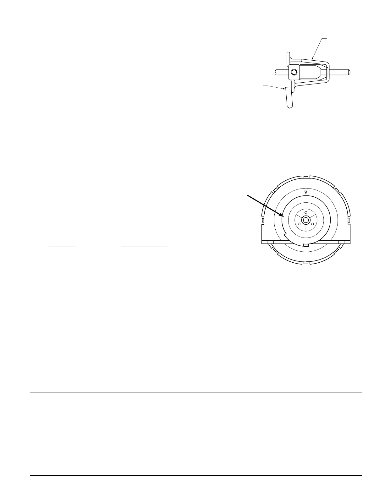
Switch Enclosure Replacement
TOP
TIMER STOP
PADDLE LEVER ARM
WHEN INSTALLING REPLACEMENT
DELAY MECHANISM, TIMER STOP
AND PADDLE LEVER ARM MUST BE
POSITIONED AS SHOWN.
Delay
adjustment
dial
NOTE: Retard time may exceed 90 seconds.
55
70
0
15
45
30
T
I
M
E
D
E
L
A
Y
I
N
S
E
C
O
N
D
S
N
U
M
B
E
R
O
N
D
I
A
L
I
S
A
P
P
R
O
X
I
M
A
T
E
1. Remove the three screws holding the switch enclosure.
2. Pull gently on the switch enclosure and rock slightly to
disengage the switch buttons from the timer stop.
3. Install the replacement switch enclosure using a similar
rocking action to depress the switch buttons. Do not
turn the timer stop or shaft more than 15 degrees while
replacing the switch enclosure. Check the position of
the timer stop per Figure 2.
4. Slide the switch enclosure toward the delay mechanism
until the vertical alignment boss on the plate seats into
the alignment groove one corner of the switch enclosure. (Only one will engage.) Exert pressure on the
switch enclosure holding it seated flat and pushed toward the delay mechanism while replacing the three
retaining screws. Seat firmly using approximately 6 inlbs. of torque.
System Check
1. With the dial set on zero, actuate the lever arm forward
and back checking for smooth operation of the switch
mechanism. The lever arm should operate freely with no
obstruction. The switches should activate when the arm
is moved forward and reset when the arm is released.
2. With a continuity meter installed between the (COM)
and (B) terminals on one of the switches, the following
conditions should occur:
Condition COM to B Circuit
Normal or non-flow Open circuit
Lever actuated or water flow in pipe (10 gpm) Closed circuit
3. Turn the dial to the desired delay setting and time the
response of the system to waterflow conditions as normally done on routine system tests.
4. Insure that the system returns to the non-alarm condition after the flow in the system is discontinued.
5. Replace the cover with the two security screws and
wrench (not supplied).
Figure 2.
W0205-00
Figure 3.
W0139-00
System Sensor warrants its enclosed product to be free from defects in
materials and workmanship under normal use and service for a period
of three years from date of manufacture. System Sensor makes no other
express warranty for the enclosed product. No agent, representative,
dealer, or employee of the Company has the authority to increase or alter
the obligations or limitations of this Warranty. The Company’s obligation of this Warranty shall be limited to the replacement of any part of
the product which is found to be defective in materials or workmanship under normal use and service during the three year period commencing with the date of manufacture. After phoning System Sensor’s
toll free number 800-SENSOR2 (736-7672) for a Return Authorization
number, send defective units postage prepaid to: System Sensor, Returns
N770-07-00 2 I56-0516-002
©2006 System Sensor
Three-Year Limited Warranty
Department, RA #__________, 3825 Ohio Avenue, St. Charles, IL 60174.
Please include a note describing the malfunction and suspected cause
of failure. The Company shall not be obligated to replace units which
are found to be defective because of damage, unreasonable use, modifications, or alterations occurring after the date of manufacture. In no
case shall the Company be liable for any consequential or incidental
damages for breach of this or any other Warranty, expressed or implied
whatsoever, even if the loss or damage is caused by the Company’s
negligence or fault. Some states do not allow the exclusion or limitation of incidental or consequential damages, so the above limitation or
exclusion may not apply to you. This Warranty gives you specific legal
rights, and you may also have other rights which vary from state to state.
 Loading...