

Page 1
INSTALLATION AND MAINTENANCE INSTRUCTIONS
Model 885WP-B Weatherproof Heat Detector
with Fixed Temperature Alarm
Specifications
Before installing
General Description
Mounting
Tamper-resistant Feature
Figure2
Wiring Installation Guidelines
Figure 3
Figure 4.
Three-Y
ear Limited Warranty
Please refer to insert for the Limitations of Fire Alarm Systems (I56-1558-00)
System Sensor warrants its enclosed heat detector to be free
from defects in materials and workmanship under normal use
and service for a period of three years from date of
manufacture. System Sensor makes no other express warranty
for this HEAT detector. No agent, representative, dealer, or
employee of the Company has the authority to increase or alter
the obligations or limitations of this Warranty. The Company’s
obligation of this Warranty shall be limited to the repair or
replacement of any part of the smoke detector which is
found to be defective in materials or workmanship under
normal use and service during the three year period
ear Limited W
commencing with the date of manufacture. After phoning System
Sensor for a Return Authorization Number, return defective units
postage prepaid to the Company. Please include a note describing
the malfunction and suspected cause of failure. The Company shall
not be obligated to repair or replace units which are found to be
defective because of damage, unreasonable use, modifications, or
alterations occurring after the date of manufacture. In no case shall
the Company be liable for any consequential or incidental damages
for breach of this or any other Warranty, expressed or implied
whatsoever, even if the loss or damage is caused by the Company’s
negligence or fault.
4 I56-885-00CW
Rev.1
Diameter:
Height (including base):
Weight (including base):
Operating Temperature Range:
IP Rating:
Sensitivity:
Operating Voltage:
Standby Current:
Alarm Current:
Latching Alarm:
Max .Air Velocity
10.2 cm (4")
4.8 cm (1.8")
170g (6.0 ounce)
-15qto 50qC (5qF to 122qF)
IP67
63qC (145.4qF) Fixed Temperature
8.5 to 30VDC
İ50嘕$
Min. 2mA #3.1VDC
Max. 80mA #6.5VDC
Reset by momentary power interruption
20m/s
Please thoroughly read System Sensor manual which
provides detailed information on detector spacing, placement, zoning, wiring, and special applications. Copies of
this manual are available at no charge from System
Sensor.
NOTICE: This manual shall be left with the owner/user
of this equipment.
IMPORTANT: This detector must be tested and maintained regularly in accordance with the requirements of
the local standards and regulations. The detector should be
cleaned at least once a year.
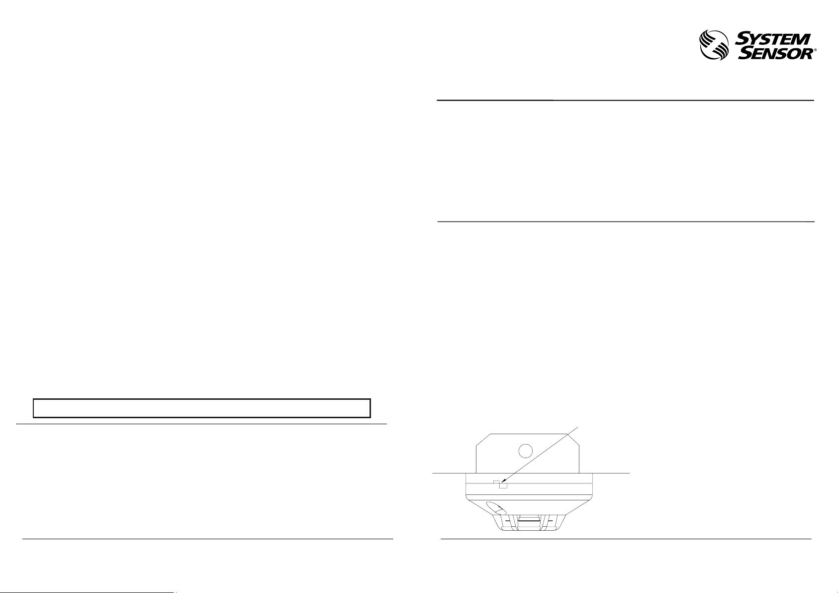
Figure1.
Surface mounting of the 885WP-B
heat detector into a 50 /60 mm junction
box.
weatherproof
Alignment when the detector is
mounted into the base
Model 885WP-B is a 2-wire fixed temperature (63qC) heat
detector. This detector is designed to provide open area
protection in areas subject to moisture. This detector is
sealed against the entry of moisture to a rating of IP67.
The LED will latch on when the detector is in alarm.
Each 885WP-B detector is used with a mounting base that
permits the detector to be mounted directly to a 50 mm or
60 mm junction box.
This detector includes a tamper-resistant feature that
prevents its removal from the mounting base without the
use of a key. To make the detector tamper-resistant,
remove the tab from the tamper arm on the mounting base
using a cutting tool. Remove the tamper key from the
center of the mounting base by twisting it back and forth
several times (see
). Once the detector is installed,
it may be removed from the mounting base by inserting
the T-shaped end of the key into the slot on the side of the
unit and rotating the detector counter-clockwise.
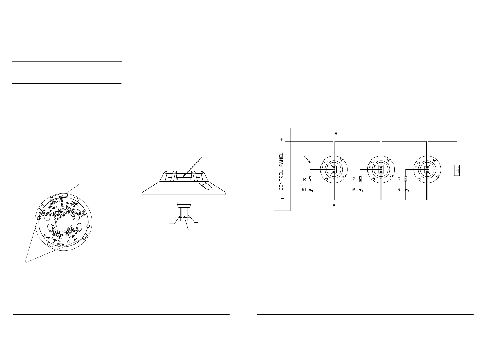
This detector provides six wires which are divided into
three groups, separately two red, two white and two black
wires. Refer to
. .
Terminal Notes:
Red wire: Power / Detector Circuit +ve
Black wire Power / Detector Circuit -ve (the power and
the LED uses the same cathode)
White wire Remote LED +ve
Wiring Diagram refers to
1 I56-885-00CW
Page 2
Installation
Testing
Figure2.
Module 885WP-B weatherproof Heat
Detector
Mounting Bracket
Testing
Maintenance
Figure 3.
Maintenance
Figure 4. Detector Wiring Diagram
NOTE: All wiring must conform to applicable local
codes, ordinances and regulations.
NOTE: Verify that all detector bases are installed, that the
initiating-device circuits have been tested, and
that the wiring is correct.
Remove power from initiating-device circuits before in-
WARNING
stalling detectors.
1. Place the detector on the mounting base and rotate
clockwise until it drops into place.
2. Turn the detector clockwise in the mounting base until
it clicks into place.
3. After all detectors have been installed, apply power to
the control unit or initiating-device circuits.
4. Test the detector as described in
5. Reset the detector at the system control panel.
Te
.
6. Notify the proper authorities the system is in
operation.
ALIGNMENT
Module 885WP-B weatherproof Heat
NOTCHES
TEMPER ARM
(CUT OFF SMALL TAB TO ACTUATE TAMPER-RESIST
FEATURE-DEPRESS ARM WITH KEY TO
REMOVE DETECTOR)
TAMPER
KEY
NOTE: Before testing, notify the proper authorities that
the thermal detector system is undergoing maintenance and will temporarily be out of service.
Disable the zone or system undergoing mainte-
nance to prevent unwanted alarms.
Detectors must be tested after installation as well as after
each time maintenance is performed.
Test the 885WP-B as follows:
To test the 885WP-B you need a hair dryer. From the
side of the detector, direct the heat toward the sensor.
Hold the heat source about 15 cm away to prevent
damage and apply heat to the cover during testing
until it alarms.
A detector that fails these tests should first be cleaned as
outlined in the
the detector still fails , it should be returned for repair.
section which follows. If
Notify the proper authorities the system is back on line.
BLACK (-ve 2 wires)
WHITE (Remote LED +ve 2 wires)
Metal heat Collector
RED (+ve 2 wires)
1. Remove the detector from the mounting base by
rotating it counter-clockwise.
NOTE: Before removing the detector, notify the proper
authorities that the fire detection system is
undergoing maintenance and will temporarily be
out of service. Disable the zone or system
undergoing maintenance to prevent unwanted
alarms.
2. Vacuum the metal heat collector and surrounding area.
3. Clean the surface of the detector.
4. Reinstall the detector.
5. Test the detector as described in
Testing.
6. Notify the proper authorities the system is back in
operation.
RED wires
WHITE wire
BLACK wires
2 I56-885-00CW
3 I56-885-00CW
 Loading...