

Page 1

INSTALLATION AND MAINTENANCE INSTRUCTIONS
I56-3620-005
8100 FAAST
Fire Alarm Aspiration Sensing Technology
SPECIFICATIONS
Electrical Characteristics
External Supply Voltage 18 – 30 VDC
Remote Reset Time External monitor must be pulled low for a minimum of 100 msec.
Power Reset 1 sec.
Average Operating Current 500 mA @ 24 VDC
Alarm 650 mA – All relays active, all alarm levels displayed. Voltage @ 24 VDC
Relay Contact Ratings 3.0 A @ 30 VDC, 0.5A @ 125 VAC
Environmental Ratings
Operating Temperature 32°F (0°C) to 100°F (38°C)
Sampled Air Temperature -4°F (-20°C) to 140°F (60°C)
Humidity 10 to 95% (non-condensing)
IP Rating IP30
Coverage Area 8,000 sq. ft. (743.2 sq. m.)
Air Movement 0 – 4,000 ft./min. (0-1,219.2 m/min.)
Mechanical characteristics
Exterior Dimensions
Height 13.25 in. (33.66 cm)
Width 13.0 in. (33 cm)
Depth 5.0 in. (12.7 cm)
Cable Access 4 – 1 in. (2.54 cm) cable entry holes on top and bottom of unit.
Wire Gauge 12 AWG (2.0523 mm) max. to 24 AWG (0.5105 mm) min.
Pipe Network Size Up to 8000 sq. ft. (approx 743 sq. m)
Maximum single pipe length 262 ft. (80 m)
Network outside pipe diameter 1.050 in., IPS (25 mm)
Internal pipe diameter .591 to .827 in. (15-21 mm)
Shipping Weight 11.6 lbs. (5.26 kg), includes packing material
®
3825 Ohio Avenue, St. Charles, Illinois 60174
1.800.SENSOR2; Fax: 630.377.6495
www.systemsensor.com
TABLE OF CONTENTS
INTRODUCTION
SCOPE OF THIS MANUAL ...........................................2
DESCRIPTION
FEATURES .......................................................2
ITEMS INCLUDED WITH UNIT .......................................2
INSTALLATION
PIPE INSTALLATION ............................................... 2
PHYSICAL UNIT INSTALLATION ...................................... 2
Securing the Mounting Bracket ................................2
Mounting the Detector to the Bracket ...........................3
Connecting the Air Sampling Pipe ..............................3
Exhaust Pipe ................................................3
WIRING .......................................................3
Power Cables ...............................................3
Conduit Usage ..............................................3
CABLING REQUIREMENTS .......................................... 4
SYSTEM POWERING ...............................................4
USER INTERFACE
USER INTERFACE CARD INSTALLATION ...............................5
PARTICULATE LEVEL DISPLAY .......................................5
ALARM LEVEL DISPLAY ............................................ 5
AIR FLOW/FAULT DISPLAY ..........................................5
Labels .....................................................5
USER INTERFACE BUTTONS ........................................5
MODES OF OPERATION
INITIALIZATION ...................................................6
STARTUP .......................................................6
CONFIGURATION ................................................. 6
Failure of Configuration Validation ..............................6
SS-400-007 1 I56-3620-005
Power or Network Loss during Configuration ......................6
NORMAL MODE .................................................. 6
TEST MODE. . . . . . . . . . . . . . . . . . . . . . . . . . . . . . . . . . . . . . . . . . . . . . . . . . . . . . 6
RESET MODE .................................................... 6
ACCLIMATE ......................................................6
Setting Acclimate mode .......................................6
DAY, NIGHT AND WEEKEND MODE ...................................7
ISOLATION .......................................................7
USER BUTTON ALTERNATE FUNCTIONS ...............................7
Passcode Access ............................................7
Address Blink Mode ..........................................7
IP Address Blink Mode ........................................7
FAULTS .......................................................8
REAL–TIME CLOCK ...............................................8
LOGS .......................................................8
Event Log ..................................................8
Data Trend Log ..............................................8
Message Log ...............................................8
EXTERNAL MONITOR/RESET ........................................8
ETHERNET CONNECTION. . . . . . . . . . . . . . . . . . . . . . . . . . . . . . . . . . . . . . . . . . . 8
PIPE NETWORK .................................................. 8
WEB SERVER .................................................... 9
E-MAIL NOTIFICATION. . . . . . . . . . . . . . . . . . . . . . . . . . . . . . . . . . . . . . . . . . . . . . 9
CANNED SMOKE TESTING ..........................................9
MAINTENANCE ...................................................9
GLOSSARY
KEY TERMS .....................................................9
Page 2
INTRODUCTION
WARNING
WARNING
Mounting Stud
SCOPE OF THIS MANUAL
This manual is intended as a guide for technicians to install, set up and provide preliminary system checks for the FAAST (Fire Alarm Aspiration Sensing
Technology) aspirating smoke detection system. Before installing, please read
the Comprehensive Instruction Manual for the FAAST aspiration detection system (available on PipeIQ CD or at SystemSensor.com/faast), which provides
detailed information on pipe design and system configuration.
INSTALLATION
This equipment must be installed in accordance with all local and national
codes and regulations.
PIPE INSTALLATION
The pipe layout is designed using the PipeIQ software package. Refer to the
Comprehensive Instruction Manual that comes with the PipeIQ software package to design the pipe network. All pipe must be installed in accordance with
local and national codes and regulations. The pipe network should be complete before proceeding with the physical and electrical system installation.
The performance of the system depends on the designed pipe network for
PHYSICAL UNIT INSTALLATION
the site. Any alteration to the pipe network will alter the performance of the
system and must be verified by a technician. The PipeIQ® design tool can
be used to verify the suitability of any pipe network design and subsequent
alterations. The PipeIQ software program is available from your distributor or
can be downloaded from systemsensor.com/faast.
Make sure that there are no pipes or electrical wires within the wall before
drilling any mounting holes.
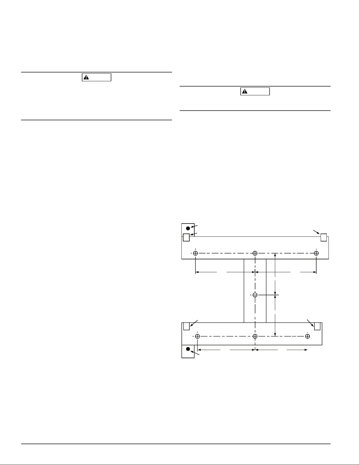
Securing the Mounting Bracket
The typical mounting location for the FAAST unit is on a wall. The unit is
DESCRIPTION
The 8100 FAAST aspirating smoke detection system is an advanced particulate
detection system for use in early warning and very early warning applications.
The system continuously draws air from the controlled environment (up to
8,000 sq. ft.) through a series of sampling holes to monitor the environment
for smoke particulate.
FAAST system conditions are displayed at the user interface and at a fire alarm
control panel via relays. System conditions can also be displayed remotely in
two ways through the network interface: integrated Web server or PipeIQ software. The display provides a clear indication of the system status, particulate
levels, alarm levels, air flow and faults. Additionally, e-mail notification can be
sent upon status changes. These can all be discerned by monitoring the user
interface at either the local or remote display.
mounted to the wall using the enclosed mounting plate. Figure 1 shows the
wall mounting plate. For easier access to the FAAST unit, it is preferred to
position the mounting plate in an easily accessible location.
1. Place the mounting bracket on the wall in the desired location and use it as
a template to locate the necessary mounting holes.
2. Mark the hole locations and remove the bracket. It is recommended to
secure the bracket using the 4 outer mounting holes.
3. Using a drill and the proper size bit for your mounting hardware, drill the
necessary holes.
4. Use appropriate fasteners to accommodate the mounting surface and
FAAST device weight.
5. Secure the bracket to the wall.
FEATURES
• Advanced detection using blue LED and IR laser technology
• Monitors up to 8,000 sq. ft. (dependant on local code and ordinances)
• Wide sensitivity range of 0.00046% to 6.25% obs/ft.
FIGURE 1. WALL MOUNTING PLATE
Mounting Clip
Mounting Clip
• Programmable alarm thresholds and delays
• Eight sets of relay contacts
• Advanced dust discrimination for reduced false alarms
• Air filtration
• Particle separation for increased filter life
• Electronic filter life monitoring
4.650"
11.811 cm
3.240"/8.230 cm
4.770"
12.116 cm
• Ultrasonic air flow sensing
• Field service access door
• Easy access filter maintenance door
• Event, service and trend logs
Mounting Clip
3.210"/8.153 cm
Mounting Clip
• Pipe modeling software
• Acclimate mode operation for auto-adjustment of sensitivity
• Remote monitoring via Ethernet/IP
• Remote reset/dry contact input
• Multi-lingual support
Mounting Stud
4.500"
11.430 cm
4.090"
10.389 cm
ASP-07
• E-mail notification of alarm, fault or isolate conditions
ITEMS INCLUDED WITH UNIT
• FAAST unit
• Mounting bracket
• Mounting nuts (2) and washers (2)
• 3-pin Terminal block (9)
• 4-pin Terminal block (1)
• 47 K-ohm EOL Resistor
• Installation and Maintenance Instructions
• PipeIQ software, comprehensive instruction manual, and advanced
networking white paper may be downloaded at systemsensor.com/faast
SS-400-007 2 I56-3620-005
Page 3
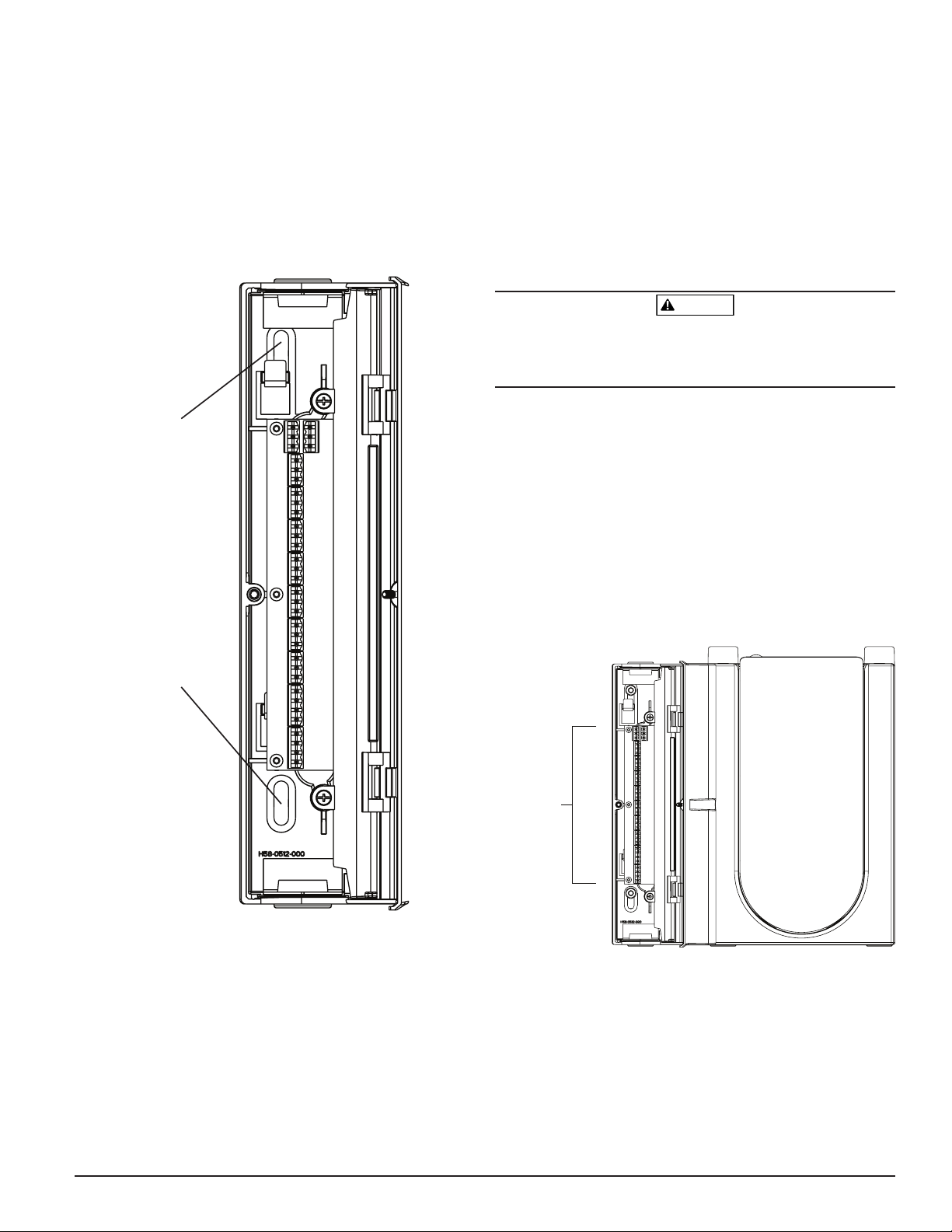
Mounting the Detector to the Bracket
Po
Once the mounting plate is attached, the unit is ready to be mounted onto the
plate. Perform the following procedure to mount the unit.
1. Before installing the unit onto the bracket, remove the appropriate conduit cap from the top or bottom-left side of the unit to match the orientation of the wiring. See Figure 14 for location of the wiring access plugs.
2. Line up the unit with the four mounting clips and the mounting studs on
the left side.
3. Push the unit down onto the mounting clips and secure it with the supplied washer and nut on at least one of the two mounting studs protruding through the mounting slots shown in Figure 2.
FIGURE 2. MOUNTING SLOTS FOR MOUNTING STUDS
Mounting
Slot
Mounting
Slot
Exhaust Pipe
The device should always be exhausted into the space that it is monitoring.
There are some circumstances when it may be necessary to connect a pipe to
the exhaust port to divert the exhaust away from the location of the unit. The
output ports are tapered the same as the input ports, to provide fast, easy,
push-fit connection of an exhaust pipe to the unit. Perform the following procedure to connect the exhaust pipe to the unit.
1. Square off and de-burr the end of the exhaust pipe. Ensure that the pipe
is free from any particles that might interfere with the pipe connection.
2. Remove the exhaust plug from the output port being used (either the top
or bottom of the unit).
3. Insert the exhaust pipe into the output port, ensuring a snug fit. DO NOT
glue these pipes.
WIRING
WARNING
Before working on the FAAST system, notify all required authorities that the
system will be temporarily out of service. Make sure all power is removed
from the system before opening the unit. All wiring must be in accordance
with local codes.
Power Cables
Use the power ratings of the unit to determine the required wire sizes for each
connection. Use the power ratings of the connected products to determine
proper wire size.
Conduit Usage
If electrical conduit is used for system wiring, terminate the conduits at the cable
entry ports on the top or bottom of the unit, using the appropriate conduit connectors.
1. Run all wiring, both power and alarm, through the conduit and into the
left side of the unit enclosure, as shown in Figure 3.
2. Attach the appropriate wires to the supplied Euro connector. Follow appropriate local codes and electrical standards for all cabling.
3. Plug the appropriate connector into the mating connector on the unit.
FIGURE 3. POWER AND ALARM CONNECTION CONNECTOR BLOCK
wer and Alarm
Connections
ASP-17
Connecting the Air Sampling Pipe
The input and output ports are designed to accept standard one inch pipe (25
mm) OD. The input ports are tapered to provide fast, easy, push-fit connection
of the sampling pipe to the unit. Perform the following procedure to connect
the air sampling pipe to the unit.
1. Square off and de-burr the end of the sampling air pipe. Ensure that the pipe
is free from any particles that might interfere with the pipe connection.
2. Remove the input plug from the input port being used (either the top or
bottom of the unit).
3. Insert the sampling air pipe into the input port, ensuring a snug fit.
DO NOT glue these pipes.
SS-400-007 3 I56-3620-005
ASP-16
Page 4
CABLING REQUIREMENTS
Fire Panel (FACP) typical connection
FAAST 8100
®
Fire Alarm Aspiration Sensing Technology®
The FAAST system provides a series of Euro style pluggable terminals, located
behind the left side door of the unit.
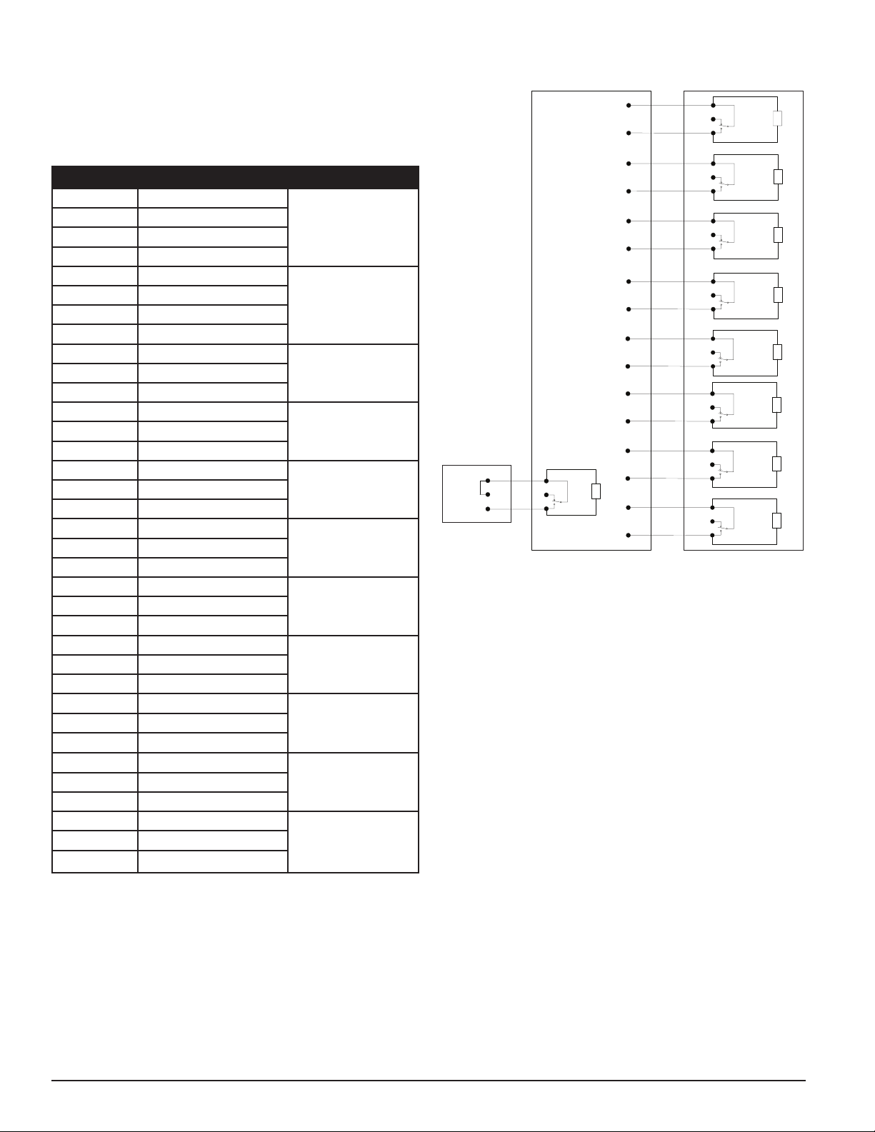
Refer to Table 1 for the proper electrical connections to the unit. Refer to Table
2 for a typical connection for monitoring the FAAST system at a Fire Alarm
Control Panel (FACP).
TABLE 1. TERMINAL DESIGNATIONS
NUMBER NAME TERMINAL BLOCK
T1 External Power -
T2 External Power -
T3 External Power +
1
T4 External Power +
T5 N/A
T6 N/A
T7 N/A
2
T8 N/A
T9 Alert NO
T10 Alert COM
3
T11 Alert NC
T12 Action 1 NO
T13 Action 1 COM
4
T14 Action 1 NC
T15 Action 2 NO
T16 Action 2 COM
5
T17 Action 2 NC
T18 Fire 1 NO
T19 Fire 1 COM
6
T20 Fire 1 NC
T21 Fire 2 NO
T22 Fire 2 COM
7
T23 Fire 2 NC
T24 Minor Fault NO
T25 Minor Fault COM
8
T26 Minor Fault NC
T27 Urgent Fault NC
T28 Urgent Fault COM
9
T29 Urgent Fault NO
T30 Isolate NO
T31 Isolate COM
10
T32 Isolate NC
T33 Ext Monitor/Reset -
T34 Ext Monitor/Reset -
11
T35 Ext Monitor/Reset +
TABLE 2. FACP WIRING DIAGRAM
FAAST 8100
Reset
Short =
Open = Fault
Monitor
for monitoring of device
Alarm
Short = Fire
Open = Fault
Alarm
Short = Fire
Open = Fault
FACP
Alarm
Short = Fire
Open = Fault
Alarm
Short = Fire
Open = Fault
Alarm
Short = Fire
Open = Fault
Supervisory
Short = Isolate
Open = Fault
Supervisory
Short = Urgent Fault
Panel
Remote
Reset
Open = Fault
EOL
47K
Supervisory
Short = Minor Fault
Open = Fault
-
-
+
C. (Reset)
N.C.
N.O.
Fire Alarm Aspiration Sensing Technology
C.
N.C.
N.O.
Fire2 Relay
C.
N.C.
N.O.
Fire1 Relay
C.
N.C.
N.O.
C.
N.C.
N.O.
C.
N.C.
N.O.
C.
N.C.
N.O.
C.
N.C.
N.O.
C.
N.C.
N.O.
(T7)
Contacts
(T6)
Contacts
Relay
Action2
Contacts
Relay
Action1
Contacts
(T3)
Contacts
Alert Relay
(T10)
Contacts
Isolate Relay
(T9)
Contacts
Urgent Relay
(T8)
Contacts
Minor Relay
EOL
EOL
EOL
(T5)
EOL
(T4)
EOL
EOL
EOL
EOL
ASP18-02
SYSTEM POWERING
The following procedure describes how to initially power up the FAAST system.
1. Unplug the unit’s power connector to the unit before turning ON the
power.
2. Turn on the power.
3. Check the voltage at the connector. Make sure it is within the required
voltage range.
4. If the voltage is within the proper range, reconnect the power connector
to the unit.
5. Verify the system fan starts up and air begins to flow out of the exhaust port.
6. Connect a computer, with the PipeIQ software installed, to the unit using
the Ethernet connection on the bottom of the unit.
7. Use the PipeIQ software to set up the unit configuration required for the
particular application.
8. When the configuration is complete, remove the Ethernet connection to
the unit.
SS-400-007 4 I56-3620-005
USER INTERFACE
The user interface, shown in Figure 4, provides the following information:
• Detector Status: Normal, Alarm, Fault or Isolate
• Alarm Level; Alert, Action 1, Action 2, Fire 1 and Fire 2
• Particulate Levels; 1-10 relative to Alert
• Fault Status
• Flow Level
• Test, Reset and Isolate Buttons
Page 5

GREEN LEDs
FIGURE 4. USER INTERFACE DISPLAY
Alarm Level
Indicator
Particulate Level
Indicator
These alarm levels are configured at default levels when shipped. They may be
modified using the PipeIQ software tool. Each of these alarm levels controls a
set of form C relay contacts. When an alarm level threshold is crossed, the corresponding level LED illuminates and the relay activates a signal.. These alarm
levels and associated relay outputs can be programmed for either latching or nonlatching operation, in addition to a programmable delay for each level from 0 to
60 seconds. The programmable ranges for each level are shown in Table 3.
FIGURE 6. ALARM LEVEL DISPLAY
Power
Indicator
ASP-08
USER INTERFACE CARD INSTALLATION
The user interface card must be installed on the front panel of the FAAST
aspirating smoke detection system. For installation, first slide the card into
the bottom pocket, then beneath each of the mounting tabs. If necessary,
use a flathead screwdriver to gently press the card in place beneath each of
the mounting tabs. The card is moderately flexible to allow for some bending
during installation. The user interface card is available in various languages.
PARTICULATE LEVEL DISPLAY
The particulate level display, shown in Figure 5, consists of ten amber LEDs
that correspond to the current level of the particulate detected. The LEDs illuminate in order from Level 1 to Level 10, starting from the bottom of the
display and moving up as the particulate level increases. Each LED represents
a ten percent increase in the particulate level necessary to reach the Alert
Alarm Level.
FIGURE 5. PARTICULATE LEVEL DISPLAY
ASP-10
AIR FLOW/FAULT DISPLAY
The FAAST system uses ultrasonic airflow sensing and displays the status in
real time on the User Interface. The air flow/fault display consists of 10-bicolor LEDs and operates in one of two modes. A fault warning occurs when
airflow increases or decreases by 20% or greater. The green segments indicate
how close the current air flow is to either of these thresholds. During normal
operation two adjacent indicators are green and correspond to the current airflow entering the detector. When airflow is at a balanced level the two green
segments are centered on the graph at levels 5 and 6, see Figure 7. As airflow rises and falls, the green segments move right and left accordingly. The
segment on the far left represents a decrease in airflow of 20%. Conversely,
movement to the segment on the far right represents an airflow increase of
20%. A flow fault occurs within 3 minutes of reaching either of these levels
and the minor fault relay is indicated. If the detected airflow is greater or less
than a 50% change from normal, the urgent fault relay is indicated. During a
fault condition, the fault LED as well as the corresponding high or low fault
segment is lit in amber.
Labels
Detector faults are labeled adjacent to the indicators on the Air Flow Fault graph.
FIGURE 7. BALANCED AIR FLOW
ASP-14
USER INTERFACE BUTTONS
The user interface has three buttons, shown in Figure 8, that are used to operate the unit. Functionality of these buttons are locked out by default from
the factory and require a passcode to enable them (refer to Passcode Access
section). The passcode can be programmed from the PipeIQ software tool.
FIGURE 8. USER INTERFACE BUTTONS
ASP-09
ALARM LEVEL DISPLAY
The Alarm Level Display consists of five red LEDs that correspond to the current alarm level, shown in Figure 6. These LEDs are located directly above the
Particulate Level LEDs. They illuminate sequentially upward as the severity of the
alarm increases.
ASP-11
SS-400-007 5 I56-3620-005
Page 6

TABLE 3. ALARM LEVEL PROGRAMMABLE RANGES
ALARM LEVEL DEFAULT THRESHOLD
%OBS/FT.
Alert 0.012 0.00046-6.25 0.0396 0.0015-20.5
Action 1 0.050 0.0010-6.25 0.165 0.0033-20.5
Action 2 0.100 0.0030-6.25 0.33 0.0102-20.5
Fire 1 0.250 0.012-6.25 0.825 .039-20.5
Fire 2 0.500 0.012-6.25 1.65 .039-20.5
NOTE: Installation must be accomplished in accordance with all local codes and regulations.
Product is UL certified to UL268. The 8100 FAAST is UL approved from 0.00046 %/ft obs. to 4.0%/ft obs. Evacuation via FACP (fire alarm control panel) must
not be set higher than 0.743 %/ft obs. Product UL approved sensitivity range for D(l) classification is from 0.5 to 0.61 %/ft obs. from 300 to 4000 FPM. Evacuation via FACP (fire alarm control panel) must not be set higher than 0.735 %/ft obs. Product is approved for air velocity range from 100 to 4000 FPM.
PROGRAMMABLE RANGE
%OBS/FT.
DEFAULT THRESHOLD
%OBS/M
PROGRAMMABLE
RANGE %OBS/M
MODES OF OPERATION
INITIALIZATION
When the FAAST system is first installed it is not configured and gives a fault
indication by illuminating the configuration fault LED indicator. This indicates
that the device has not had its initial configuration loaded and remains in this
state until it is initially configured (refer to the Configuration section below for
further instructions). Once configuration has started, the device performs an
automatic initialization. This initialization sets the air flow baseline, the filter
clogged baseline and the particulate level baseline. It is important that the system is connected properly and the filter is installed correctly when the device
is initialized. These initial readings are used as a reference baseline to indicate
when a fault occurs. Innitialization may take up to five minutes to complete.
STARTUP
Once powered, the FAAST system scrolls the particulate display in green for
one second and then initializes using its stored configuration. The device
checks and establishes its initial airflow, filter and fan settings. If all measurements are normal it begins normal operation. If any fault is detected the appropriate fault LED will illuminate.
CONFIGURATION
The FAAST system is configured using the software included in PipelQ. Data
is sent via the built-in Ethernet connection. The device receives the configuration and performs a validation before the configuration becomes active. After
validation of the data, the device performs an initialization with the new configuration.
Failure of Configuration Validation
If configuration validation fails, the software configuration tool indicates a
failure and the FAAST system illuminates the amber CONFIGURATION fault
LED on the user interface. The device will not accept any of the data as valid.
If a configuration fault occurs during the initial configuration or the device is
unable to operate due to the configuration, a Major fault relay will be set. The
device must be re-configured using PipeIQ. If the configuration fault occurs
after the initial configuration has been accepted, a Minor Fault relay will be set
and the device reverts back to its last valid configuration.
Power or Network Loss during Configuration
During an upload of configuration data, the FAAST system keeps the last
known valid configuration in memory until a complete validation is completed on the new configuration data. This prevents data corruption in the
event of a power loss or network failure. When power is restored the device
performs a Startup with the last valid configuration. The device also indicates
a CONFIGURATION fault on the user interface and sets the Minor Fault Relay.
This occurs only once. When the next Reset or Power On Reset is performed
the device continues to use the last valid configuration.
TABLE 4. ACCLIMATE LEVELS
ALARM LEVEL THRESHOLD HIGH
SENSITIVITY
NORMAL MODE
In Normal operating mode the FAAST system displays the air flow and current
particulate levels on the user interface. The particulate level is compared to
the threshold levels programmed into the device and activates the appropriate
alarm as particulate levels exceed that threshold. If any fault occurs it activates the corresponding fault LED and relay.
TEST MODE
Test mode is initiated through the PipeIQ Live View tab or by depressing the
TEST button on the user interface, when the button is enabled (refer to passcode access section for activation details). Test mode simulates a fire condition, activating all ten segments in the Particulate Level display and each
segment in the Alarm display. Each corresponding alarm relay is also activated after any programmed delay associated with that relay. Activation of the
RESET button removes the device from TEST mode.
RESET MODE
Reset mode is initiated through the PipeIQ Live View tab or by depressing the
RESET button on the user interface, when the button is enabled (refer to passcode access section for activation details). When RESET is activated all relays
are reset. The device then enters Normal mode operation. If any fault or alarm
states remain, the device re-activates the state automatically.
ACCLIMATE
The FAAST system includes an available Acclimate mode. By allowing the device to operate in Acclimate mode, a device’s susceptibility to nuisance alarms
can be reduced. This provides maximum protection for a device located in
changing environments. The sensitivity of the unit continuously adjusts over
time, within the set limits as the local environment changes. Acclimate mode
must be activated and configured with the software configuration tool which
is part of the PipeIQ software package. In Acclimate mode the device automatically adjusts the alarm point between a specified minimum and maximum
sensitivity, programmed by the user. For the first 24 hours of operation the
device monitors its environment. After the initial 24 hour period, the device
adjusts the alarm point based on the particulate levels over a rolling 1 hour
period. It then adjusts the alarm level starting from the insensitive boundary,
based on the stability of the environment being monitored.
Setting Acclimate mode
The user chooses the boundaries for each alarm level in the Acclimate mode.
The FAAST system starts from the insensitive boundary and adjusts itself to
stay within the sensitive boundary. It is also possible to have a static alarm
level by adjusting the high and low boundary to the same level. This allows
the flexibility to maintain acclimating levels for some alarms and static levels
for others. Table 4 shows the various levels that are available.
Each Acclimate level is also available for monitoring with the PipeIQ tool.
This allows the user to read the current Acclimated alarm level for each alarm.
THRESHOLD LOW
SENSITIVITY
CURRENT LEVEL
Alert Alert High Alert Low Acclimate Alert Level
Action 1 Action 1 High Action 1 Low Acclimate Action 1 Level
Action 2 Action 2 High Action 2 Low Acclimate Action 2 Level
Fire 1 Fire 1 High Fire 1 Low Acclimate Fire 1 Level
Fire 2 Fire 2 High Fire 2 Low Acclimate Fire 2 Level
SS-400-007 6 I56-3620-005
Page 7

DAY, NIGHT AND WEEKEND MODE
If Acclimate mode is not desired, the FAAST system can operate in a simple
day, night and weekend mode. This allows the device to have separate threshold levels for each state. Times can be configured, if desired, for entering and
leaving day and night time operation. The device has an internal time reference (clock) and automatically switches to the weekend mode for Saturday
and Sunday.
ISOLATION
Isolation mode is initiated by pressing and releasing the ISOLATE button on
the user interface when the button is enabled (refer to the passcode section).
When the ISOLATE button is activated the FAAST system resets the fault and
alarm relays. It then sets the isolation relay and the isolation fault indicator
illuminates on the user interface. In this mode the device operates normally
but will not activate relays for any alarm or fault levels (except the Isolation
relay). Fire and fault events can still be seen on the user interface and the web
server will send e-mail notification of events if enabled. Isolation mode will
be held through resets and power outages. The device will remain in isolation
mode until the isolation mode is removed by pressing the ISOLATE button.
ISOLATE mode may be enabled and disabled using the monitoring portion
of PipeIQ.
DISABLE
Disable mode is initiated by pressing and holding the ISOLATE button on the
user interface for 3 seconds when the button is enabled (refer to the passcode
section). When the ISOLATE button is activated, the FAAST system resets the
fault and alarm relays. It then sets the isolation relay and the isolation fault
indicator illuminates on the user interface. In this mode the fan switches off
and the device does not report any alarm or fault levels on the user interface
or activate any relays (except the Isolation Relay). This mode should only
be used when the system needs to be taken offline. This mode will be held
through resets and power outages. The device will remain in disable mode
until the disable mode is removed by pressing the ISOLATE button. Disable
mode cannot be enabled or disabled using the monitoring portion of PipeIQ.
USER BUTTON ALTERNATE FUNCTIONS
Passcode Access
The user interface has an option that requires users to enter a security code
before the front panel functions become active. All passcodes must be 4 digits
in length using numbers 1 through 9 (zero cannot be used). Passcodes may
only be changed through the PipeIQ software program. In addition, the configuration software tool is capable of locking out buttons individually, so that
certain buttons may be accessed without a passcode, if desired.
The default passcode is ‘1111’.
The TEST button enters digits, the RESET button is used to enter the unlock
mode and the ISOLATE button increments the current digit.
To enter the passcode mode, press and hold the RESET button for 8 seconds.
The first segment on the flow indicator first illuminates yellow, then green.
When the segment illuminates green, release the RESET button. The first segment on the airflow display blinks green, indicating the device is ready to
accept the first digit.
FIGURE 9. PASSCODE ACCESS BUTTONS
ASP-11
FIGURE 10. ADDRESS BLINK MODE
ASP-12
Address Blink Mode
The unit has two types of addressing capabilities. In addition to the IP Address, the FAAST system can also have a local address that is assigned through
the configuration software. The address can be between 1 and 255. This address can be accessed from the user interface by pressing and holding the
RESET button for 3 seconds. After 3 seconds, the first segment on the airflow
display illuminates amber, shown in Figure 10, indicating the device is in address blink mode. Release the RESET button and the device shows the 3 digit
number assigned by lighting the particulate bar graph with the appropriate
number of segments for each digit. The current digit displayed is indicated
by the 3 left most indicators on the air flow graph. The first digit is the 100’s
and illuminates for 2 seconds. Next, the tens digit illuminates for 2 seconds,
followed by the ones digit illuminating for 2 seconds. If one of the numbers is
zero, then no lights will illuminate for that number on the particulate graph.
The device then returns to normal operating mode.
IP Address Blink Mode
If the device IP has been lost or is unavailable, it’s possible to obtain the address
using the IP address blink mode. The IP address can be accessed from the user
interface by pressing and holding the RESET button for 30 seconds. The digits are
displayed using the same method described in the address blink mode, except
that the FAULT and LOW VOLTAGE indicators are used to show the 1st and 12th
digit, respectively. The device gives the 12 digit number by illuminating the particulate bar graph to the appropriate number of segments for each digit, as shown
in Figure 11. The example shown in Figure 11 shows that the 5th number of the
IP address is 7. The current digit displayed is indicated by the FAULT, FLOW /
FAULT and VOLTAGE indicators (figure 12) starting with the FAULT for the 1st
digit, progressing through the HIGH FLOW, and ending with the LOW VOLTAGE
for the 12th digit. If one of the numbers is zero, then no lights will illuminate for that
number on the particulate graph. The device will return to normal operating mode.
FIGURE 11. IP ADDRESS BLINK MODE
Alarm Level
Indicator
Particulate Level
Indicator
Power
Indicator
To enter the passcode, use the ISOLATE and TEST buttons, shown in Figure 9.
The ISOLATE button is used to increment the current digit. As the current digit
is incremented the segments of the Particulate Bar Graph illuminate accordingly. To complete entry of the digit, press the TEST button. As each digit is
entered the airflow segment illuminates solid green and the next segment be-
ASP-15
gins to flash, indicating the next digit is ready to be entered. After the 4th digit
is entered, the fault indicator illuminates green, if the passcode was accepted
and remains green as long as the detector is “unlocked”. If the passcode was
not accepted, the fault indicator illuminates amber for 3 seconds then the
FIGURE 12. IP ADDRESS INDICATOR LIGHTS
device returns to its previous state.
Once the passcode is accepted, the locked out button(s) become active. After
45 seconds of inactivity the fault indicator begins to blink green. After an additional 15 seconds the detector re-locks the button(s) and returns to normal
operation.
Note: If the RESET button is chosen as a locked button, and a reset is initiated,
ASP-19
the device requires the passcode to regain access to the RESET button.
SS-400-007 7 I56-3620-005
Page 8

TABLE 5. FAULT DESCRIPTION
NUMBER NAME DESCRIPTION ACTIVATED RELAY
1 Low Flow Fault Device has decreased airflow of 20%. Minor Fault
Device has decreased airflow of 50%. Urgent Fault
2 Configuration Configuration of device with configuration software has failed. Minor Fault
Device was interrupted with a power loss during configuration. A Reset will
Minor Fault
clear this fault and device will revert back to it's last good configuration.
Device is new and has not been configured. Urgent Fault
Device has corrupt configuration and is unable to operate. Urgent Fault
3 Sensor Fault Device has problem with the particulate sensor and needs immediate replace-
Urgent Fault
ment.
4 External Monitor Fault External monitor detects open. Minor Fault
5 Time Fault Internal Time base needs updating. Minor Fault
6 Communication Fault Device has failed to communicate to one of it's peripherals and cannot function
Urgent Fault
properly.
7 Aspirator Fault Indicates the fan has stopped working and requires immediate attention. Urgent Fault
8 Filter Fault Device filter is clogged and requires replacement. Minor Fault
Device filter is clogged and has not been replaced 72 hours after giving the
Urgent Fault
Filter Fault with Minor Fault Relay set.
9 Isolate Fault Device has been put in isolate mode. Isolation Fault
10 High Flow Fault Device has Increased airflow of 20%. Minor Fault
Device has Increased airflow of 50%. Urgent Fault
11 Low Voltage Fault Device Input voltage is low. None
FAULTS
Whenever a fault occurs, the general FAULT indicator illuminates amber and
the flow status bar oscillates between flow status (green) and a detailed fault
status (amber). Table 5 shows the number, name, description and the activated relay for each fault. The fault display on the user interface is shown in
Figure 13.
FIGURE 13. FAULT DISPLAY
Data Trend Log
The FAAST system tracks trend data for each 24 hour time period, up to 1
year. The device records the minimum, maximum and average reading of the
sensor and flow values for each day.
Message Log
The message log allows the user to enter generic text messages into the system’s memory. Messages may be retrieved for viewing at a later time. These
messages may be used to track service history, configuration changes, etc. A
maximum of 300 messages may be stored.
EXTERNAL MONITOR/RESET
The FAAST system has an external monitor that can detect an open or a short
when the supplied 47 K-ohm end of line resistor is used. When the device
senses an open circuit it sets the External Monitor fault indicator and sets the
Minor fault relay. When a short circuit is detected the device performs a Reset.
This provides the ability to reset alarm latches remotely.
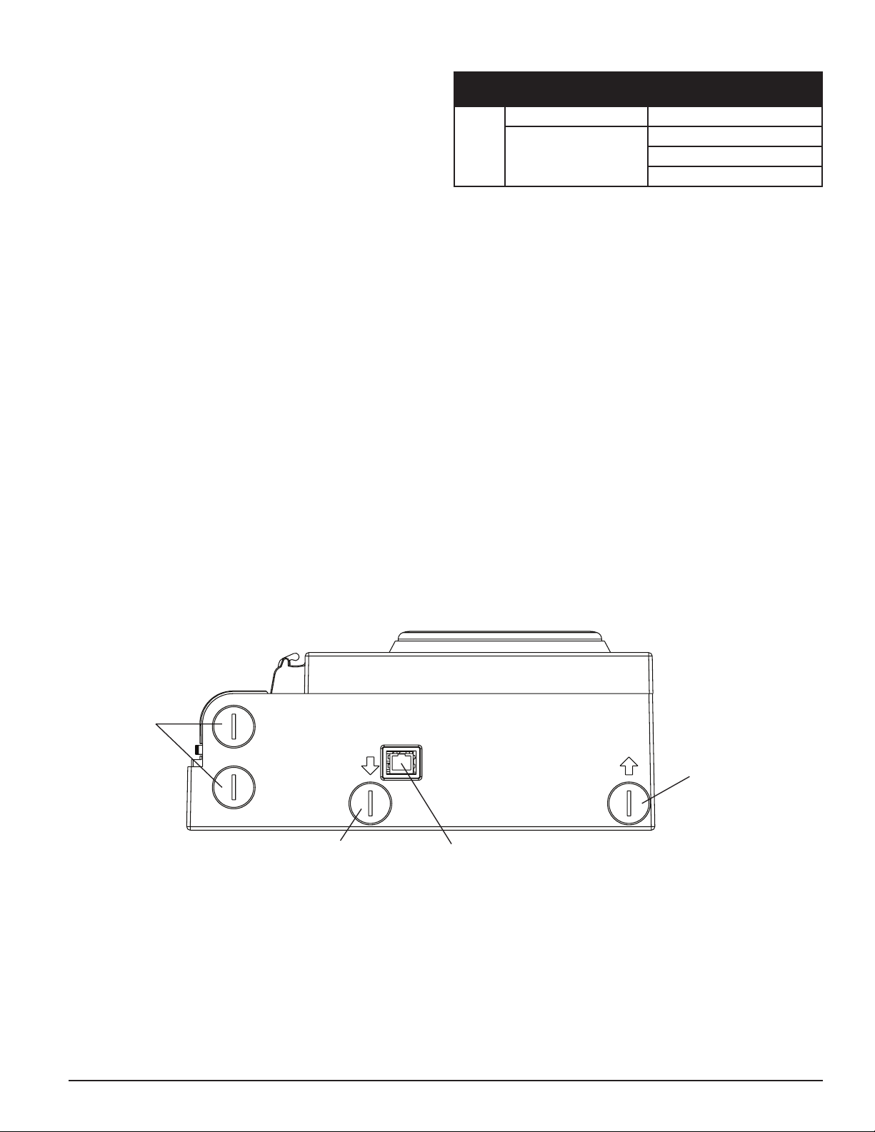
ETHERNET CONNECTION
The FAAST system is a network capable device that is compatible with standard
Ethernet networking equipment. Connectivity is provided by an onboard RJ-45
connector located on the bottom of the unit, as shown in Figure 14. The network
interface is required for initial detector configuration. Once initial setup is com-
ASP-13
REAL–TIME CLOCK
The unit is equipped with a real-time clock and power supply that allows
the FAAST system to maintain the date and time for up to 72 hours after a
loss of power. Date and time are configured through the PipeIQ software. The
real-time clock is used to maintain a time base for the device. This time base
is used to time stamp all log entries, as well as determine when it is time to
transfer from day, night and weekend modes. If the device loses power for
more than 72 hours the device sets the TIME fault indicating the time needs
to be updated.
LOGS
Event Log
The FAAST system is equipped with internal memory that can be configured
to log detector events. Up to 18,000 events can be stored. Events that are
tracked include alarms, faults and user actions. Event tracking data may be
plete, the Ethernet connection provides optional remote access, monitoring and
e-mail notification through the unit’s Web server and SMTP client.
PIPE NETWORK
The unit can monitor up to 8,000 sq.ft. (approx. 743 sq. m) with a properly
designed pipe network. The pipe network must be properly configured using
the PipeIQ software. The pipe network accommodates a maximum single pipe
length of 262 ft. (80 m). If two branches are used, the maximum single pipe
length is 165 ft. (50 m). The device is capable of both metric 25 mm and IPS
1.05 in. pipe outside diameters without the use of an adaptor. The internal
pipe diameter can range from .591-.827 inches (15-21mm). Only 1 inlet and 1
outlet pipe are used at a time. Pipe networks may be constructed of various
materials such as ABS, cPVC, PVC, copper or stainless steel pipe. Travel time
from the furthest hole depends on the application of the device, but is limited
to a maximum of 120 seconds by the PipeIQ software. Refer to local agency
requirements and PipeIQ software for proper configuration.
accessed via the network through the PipeIQ software or the Web server interface. Configuration and management of the log are done using the PipeIQ
software.
SS-400-007 8 I56-3620-005
Page 9
WEB SERVER
The FAAST system contains an integrated Web server which is used to observe detector configuration and may be used to remotely monitor the unit.
The Web server features include:
• Intuitive interface for remote monitoring of faults, relays, particulate
level, air flow, and power supply
• Facility location and contact information
• Configuration settings display
• Multi-Lingual support
• Event log viewer
E-MAIL NOTIFICATION
The FAAST system has the ability to send e-mail notifications to an individual
or organization. Up to 6 different email addresses may be stored for notification. Each email address can be configured to be notified of a specific alarm
level, fault level or isolate condition through the PipeIQ software. E-mails from
the device indicate a device’s ID, location and alarm or fault type. A comprehensive networking guide may be downloaded at systemsensor.com/faast.
CANNED SMOKE TESTING
All FAAST systems must be tested after installation and periodically thereafter.
Testing methods must statisfy the authority having jurisdiction. Systems offer maximum performance when tested and maintained in compliance with
NFPA 72. UL Tested and approved aerosol smoke products are listed in Table 6.
TABLE 6. CANNED SMOKE TESTING
UL
LISTED
MAINTENANCE
The only periodic maintenance required is to replace the filter assembly when
the filter light is illuminated. Perform the following procedure to replace the
filter assembly.
1. Remove power from the system.
2. Open the door on the right side of the device that covers the LED system
indicators.
3. Remove the plastic name card over the LEDs.
4. Remove the two screws holding the filter assembly into the device.
5. Remove the filter assembly and replace it with a new assembly.
6. Torque the two philips head screws to 6in-lb (0.7 N-M) or ¼ turn past
“lightly snug.” PLEASE DO NOT OVERTIGHTEN.
7. Replace the plastic name card over the LEDs.
8. Close the door and return power to the system.
Other system checks may need to be performed in accordance with local or
national codes and regulations.
COMPANY AEROSOL
Home Safeguard 25S
CHEK02, CHEK06
SDI LLC
SOLOA3
SMOKE SABRE-01
FIGURE 14. BOTTOM VIEW OF UNIT
Wiring
Access
Plugs
Sampled
Air Inlet
Network
Connection
Sampled
Air Outlet
ASP-03
SS-400-007 9 I56-3620-005
Page 10

FAAST System Validation Form
Customer Name:
Project Name:
Site Address:
Installer Name/Contact information: Date:
Commissioning Agent/Contact information: Date:
Client Representative/Contact information: Date:
Witness/Contact information: Date:
Wiring Checked: Date: Yes / No
Detector Settings Checked: Date: Yes / No
Test Relays: Date: Yes / No
REQUIRED DOCUMENTS
Copy of Commissioning Form Yes / No
FAAST system Bill of Material Yes / No
Commissioning Form for each system Yes / No
Smoke Test results (optional) Yes / No
Locally required forms Yes / No
Customer’s Signature: Date:
Commissioning Agent Signature: Date:
SS-400-007 10 I56-3620-005
Page 11

FAAST System Validation Form (CONT.)
Air Handling Yes / No Duct Sampling Yes / No
Number of Sample points: Number of Cabinets:
Temperature:
Conditions:
As-Built Installation
Drawings Available?
Is the power supply
installed properly?
Describe any Variations:
Sensitivity: % Obscuration/ft.:
Detector Address: Detector Address:
Day Alert: Predicted: Actual:
Action 1: Predicted: Actual:
Action 2: Predicted: Actual:
Fire 1: Predicted: Actual:
Fire 2:
Night Alert: Alarm Outputs Verified: Yes / No
Action 1: Fault Outputs Verified: Yes / No
Action 2: Isolate Function Verified: Yes / No
Fire 1:
Fire 2:
Weekend Alert:
Action 1:
Action 2:
Fire 1:
Fire 2:
Acclimate Alert:
Action 1:
Action 2:
Fire 1:
Fire 2:
Air Flow Fault
Thresholds
Low:
High:
Yes / No
Yes / No
THRESHOLD TIME DELAY TRANSPORT TIMES
Humidity:
Other:
Is the system installed in
accordance with the design?
Is the pipe network installed
and labeled properly?
Yes / No
Yes / No
SS-400-007 11 I56-3620-005
Page 12

GLOSSARY
KEY TERMS
Configure:
To set up a program or computer system for a particular application.
FAAST Fire Alarm Aspirating Sensing Technology®:
High sensitivity aspirating smoke detection system.
IP Address:
An Internet Protocol (IP) address is a numerical label that is assigned to devices participating in a computer network utilizing the Internet Protocol for
communication between its nodes.
PipeIQ®:
A software program designed to work with the FAAST unit for system configuration, monitoring and pipe design.
Web server:
A Web server is a computer program that delivers (serves) content. The device
contains an integrated Web server which is used to observe detector configuration and may be used to remotely monitor the system.
LASER SAFETY INFORMATION
This aspiration detector does not produce any hazardous laser radiation and is certified
as a Class 1 laser product under the U.S. Department of Health and Human Services
(DHHS) Radiation Performance Standard according to the Radiation Control for Health
and Safety Act of 1968. Any radiation emitted inside the smoke detector is completely
within the protective housings and external covers.
System Sensor warrants its enclosed smoke detector to be free from defects in materials
and workmanship under normal use and service for a period of three years from date
of manufacture. System Sensor makes no other express warranty for this smoke detector. No agent, representative, dealer, or employee of the Company has the authority to
increase or alter the obligations or limitations of this Warranty. The Company’s obligation
of this Warranty shall be limited to the repair or replacement of any part of the smoke
detector which is found to be defective in materials or workmanship under normal use
and service during the three year period commencing with the date of manufacture.
After phoning System Sensor’s toll free number 800-SENSOR2 (736-7672) for a Return
Authorization number, send defective units postage prepaid to: System Sensor, Returns
FCC STATEMENT
This device complies with part 15 of the FCC Rules. Operation is subject to the following two conditions: (1) This device may not cause harmful interference, and (2) this device must
accept any interference received, including interference that may cause undesired operation.
NOTE: This equipment has been tested and found to comply with Part 15 of the FCC Rules. These limits are designed to provide reasonable protection against harmful interference
in a residential installation. This equipment generates, uses and can radiate radio frequency energy and, if not installed and used in accordance with the instructions, may cause
harmful interference to radio communications. However, there is no guarantee that interference will not occur in a particular installation. If this equipment does cause harmful
interference to radio or television reception, which can be determined by turning the equipment off and on, the user is encouraged to try to correct the interference by one or more
of the following measures:
– Reorient or relocate the receiving antenna.
– Increase the separation between the equipment and receiver.
– Connect the equipment into an outlet on a circuit different from that to which the receiver is connected.
– Consult the dealer or an experienced radio/TV technician for help.
The laser beam cannot escape from the detector during any phase of operation.
The Center of Devices and Radiological Health (CDRH) of the U. S. Food and Drug
Administration implemented regulations for laser products on August 2, 1976. These
regulations apply to laser products manufactured after August 1, 1976. Compliance is
mandatory for products marketed in the United States.
WARRANTY
Department, RA #__________, 3825 Ohio Avenue, St. Charles, IL 60174. Please include a
note describing the malfunction and suspected cause of failure. The Company shall not
be obligated to repair or replace units which are found to be defective because of damage,
unreasonable use, modifications, or alterations occurring after the date of manufacture.
In no case shall the Company be liable for any consequential or incidental damages for
breach of this or any other warranty, expressed or implied whatsoever, even if the loss
or damage is caused by the Company’s negligence or fault Some states do not allow the
exclusion or limitation of incidental or consequential damages, so the above limitation
or exclusion may not apply to you. This Warranty gives you specific legal rights, and you
may also have other rights which vary from state to state.
SS-400-007 12 I56-3620-005
©System Sensor 2013
 Loading...