

Page 1
6500-MMK/SMK
MUL TI-MOUNTING KIT FOR USE WITH THE
6500* RANGE OF BEAM SMOKE DETECTORS
(These instructions have been approved by UL)
The multi-mount kit allows any of the 6500 range of beam detectors to be mounted to
either a wall or the ceiling. It is designed to create an additional alignment range in
cases where the detector and reflector cannot be mounted within 10° alignment of each
other. The kit includes the hardware necessary to mount either a single transmitter/
receiver unit or a single reflector . (To mount the transmitter/receiver, the surf ace mount
kit 6500-SMK is also required). If both the transmitter/receiver and the reflector require
additional alignment range, two kits will be needed. The kit is not compatible with the
long-range reflector kit.
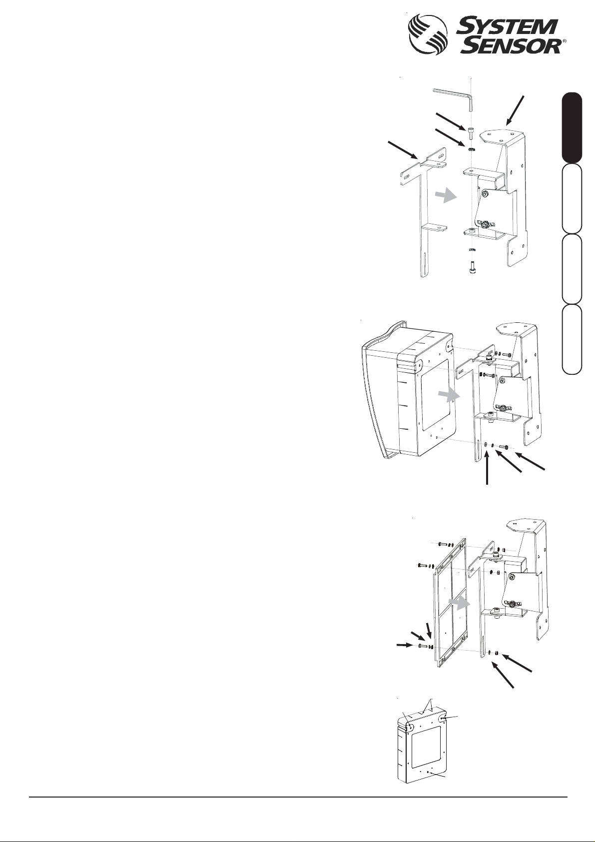
The kit comes partly pre-assembled into the following components (the parts can be
identified by matching the reference numbers to the numbers in Figs 1-3):
Qty . Description Ref. Num
1 Wall/ceiling fixed bracket 1
1 T-Bracket 2
2 M6 x 15mm hex allen head bolts 3
2 M6 split lock washers 4
3 M4 x 16mm pan head screws 5
3 M4 hex nuts 6
6 M4 washers 7
3 M4 split lock washers 8
MOUNTING THE BRACKETS
When installing to a wall or ceiling, use an appropriate anchor method to ensure the
total weight of the assembly can be securely supported. Install the fixed bracket to a
wall or ceiling so that when mounted, the transmitter/receiver and the reflector will have
a clear line of sight between them. Mount the bracket only on solid structures of the
building. To avoid unwanted alarms due to wall movement, do not mount to flexible walls ,
such as sheet metal walls (see the Detector Mounting section of the beam detector
manual for more details).
Fig. 1
2
Fig. 2
1
3
ENGLISH ITALIANO
4
ESP AÑOL
DEUTSCH
Attach the T-Bracket to the fixed bracket using the allen head bolts as shown in Fig. 1 don’t forget to use the split lock washers too. Do not fully tighten the bolts until
installation and testing are complete.
MOUNTING AND WIRING INSTRUCTIONS: TRANSMITTER/RECEIVER
The surface mount kit 6500-SMK must be used with the transmitter/receiver to provide
wiring entry.
1. Read the installation instructions of the beam detector to determine the appropriate
number of wires to be used.
2. Drill the appropriate holes for the conduit using the drill centres provided on all four
sides of the surface mount box (see Fig. SMK1-A). Conduit sizes of up to 20mm are
acceptable.
3. Mount the surface mount box on to the T-bracket of the multi-mount kit using the prethreaded holes (see Fig. SMK1-B and Fig. 2) and the M4 screws and washers.
For proper operation of the beam detector, the surface mount bo x must be:
a) Securely mounted to ensure no subsequent movement of the beam detector will
occur after the installation is completed.
b) Mounted to ensure there is line of sight between the transmitter/receiver unit
and the reflector. See the beam detector manual for further details.
4. Attach the transmitter/receiver unit (with cover and faceplate removed) securely to
the surface mount box using the four supplied screws.
5. Pull wiring and conduit through the drilled hole(s). Secure conduit fitting as required
(not supplied). Be sure to leave enough wire to reach the connectors.
6. Complete the installation and testing of the transmitter/receiver unit using the
instructions included with the beam detector. Only when installation is complete,
fully tighten the bolts connecting the T-bracket to the fixed bracket . NOTE: Ensure
all bolts are fully tightened to maintain mounting integrity!
MOUNTING INSTRUCTIONS: REFLECTOR
1. Mount the reflector on to the T-bracket of the multi-mount kit using the three M4
screws (see Fig. 3).
For proper operation of the beam detector, the reflector must be:
a) Securely mounted to ensure no subsequent movement of the reflector will
occur after the installation is completed.
b ) Mounted to ensure there is line of sight between the transmitter/receiver unit
and the reflector. See the beam detector manual f or further details.
c) Mounted so that the reflector is perpendicular to the line of sight of the
transmitter/receiver unit.
2. Complete the installation and testing of the beam detector as per its manual. Only
when installation is complete, fully tighten the bolts connecting the T-bracket to the
fixed bracket (see Fig. 3).
WARNING: If not installed correctly, the BEAM detector may not function properly.
* The 6500-MMK is also compatible with the following models:
BEAM200, BEAM200S, BEAM1224, BEAM1224s,
FSB-200S, FSB-200, BEAM355, BEAM355S
DB200-02-00 © System Sensor 2007 I56-2625-005
Important!
Important!
Fig. 3
7
8
5
Fig. SMK1
B
Pittway T ecnologica S.r.l., Via Caboto 19/3, 34147 Trieste, IT ALY
A
5
8
7
6
7
B
B
Page 2
6500-MMK
KIT MULTI-MOUNTING PER LA GAMMA 6500 DI
RILEV ATORI DI FUMO A F ASCIO
Il kit multi-mount consente l’installazione di qualsiasi dispositivo della gamma 6500
di rilevatori a fascio sia a parete che a soffitto. La sua funzione è fornire una
soluzione di allineamento supplementare nei casi in cui risulti impossibile montare il
rilevatore e il riflettore a 10° l’uno dall’altro. Il kit contiene la strumentazione necessaria
per il montaggio di un’unica unità trasmittente/ricevente o di un unico riflettore. (Per
il montaggio dell’unità trasmittente/ricevente è necessario anche il kit di montaggio
a superficie 6500-SMK). Nel caso in cui sia l’unità trasmittente/ricevente che il
riflettore necessitino di una soluzione di allineamento supplementare, saranno
necessari due diversi kit. Il presente kit non è compatibile con il kit per riflettore a
lungo raggio.
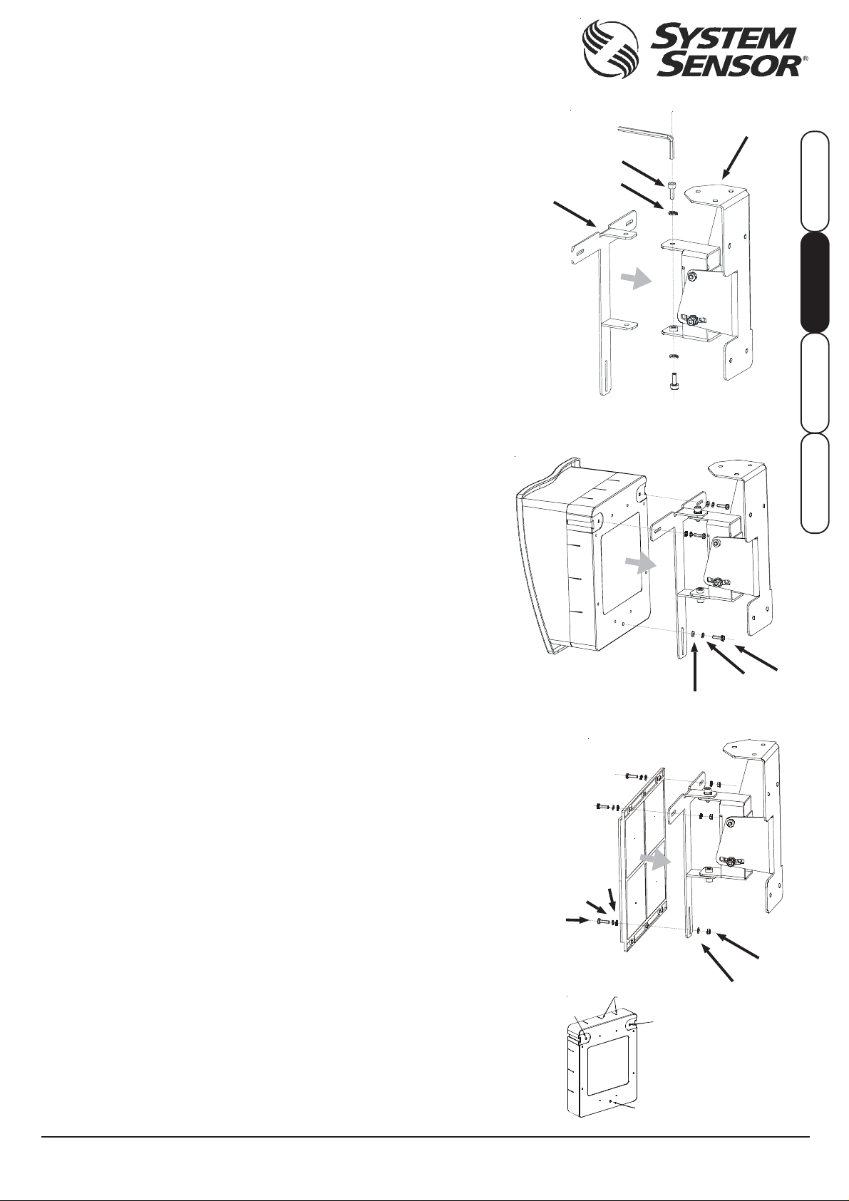
Il kit viene fornito parzialmente preassemblato con i seguenti componenti (i componenti
possono essere identificati abbinando i numeri di riferimento con i numeri riportati
nelle figure 1-3):
Qtà Descrizione N. rif.
1 Staffa fissa per montaggio a parete/a soffitto 1
1 Staffa a T 2
2 Bulloni Allen a testa esagonale M6 x 15 mm 3
2 Rondelle “split-lock” M6 4
3 Viti a testa troncoconica M4 x 16 mm 5
3 Dadi esagonali M4 6
6 Rondelle M4 7
3 Rondelle “split-lock” M4 8
MONT AGGIO DELLE ST AFFE
Al momento dell’installazione a parete o a soffitto, è importante utilizzare un metodo
di ancoraggio appropriato che garantisca il supporto in sicurezza di tutto il peso
dell’installazione. Installare la staffa fissa ad una parete o al soffitto in modo che,
quando montati, tra l’unità trasmittente/ricevente e il riflettore vi sia una chiara
visibilità. Montare la staffa solo a strutture fisse dell’edificio. Onde evitare l’attivazione
di allarmi indesiderati dovuti a movimenti della parete, non montare la staffa a pareti
flessibili quali pareti in lamine di metallo (per maggiori dettagli ved. la sezione
Montaggio del rilevatore del manuale relativo al rilevatore a fascio).
Fissare la staffa a T alla staffa fissa utilizzando i bulloni Allen a testa esagonale
come mostrato nella Fig. 1 – non dimenticare di utilizzare anche le rondelle “splitlock”. Non serrare a fondo i bulloni prima di aver completato l’installazione e la
verifica.
ISTRUZIONI DI MONT AGGIO E CABLA GGIO: UNITÀ TRASMITTENTE/RICEVENTE
Per un corretto cablaggio dell’unità trasmittente/ricevente utilizzare il kit di montaggio
a superficie 6500-SMK.
1. Leggere le istruzioni di installazione del rilevatore a fascio per stabilire il numero
appropriato di cavi da utilizzare.
2. Eseguire i fori indicati per il tubo utilizzando i centri di foratura presenti su tutti e
quattro i lati della scatola per montaggio a superficie (ved. Fig. SMK1-A). Sono
considerati idonei tubi con dimensioni fino a 20 mm.
3. Montare la scatola per montaggio a parete sulla staffa a T del kit multi-mount
utilizzando i fori prefilettati (ved. Fig. SMK1-B e Fig. 2), le viti e le rondelle M4.
Importante!
Per un corretto funzionamento del rilevatore a fascio, la scatola per montaggio a
superficie deve essere:
a) Saldamente fissata in modo che al termine dell’installazione non si verifichi
alcun movimento del rilevatore a fascio.
b ) Montato in modo tale che tra l’unità trasmittente/ricevente e il riflettore vi
sia una chiara visibilità. Per ulteriori dettagli ved. il manuale del rilevatore
a fascio.
4. Fissare saldamente l’unità trasmittente/ricevente (senza coperchio e protezione
anteriore) alla scatola per montaggio a superficie utilizzando le quattro viti in
dotazione.
5. Inserire i cavi e il tubo attraverso i fori praticati. Fissare i raccordi del tubo come
richiesto (non in dotazione). Accertarsi che vi sia cavo a sufficienza per raggiungere
i connettori.
6. Completare l’installazione e la verifica dell’unità trasmittente/ricevente seguendo
le istruzioni allegate al rilevatore a fascio. Solo al termine dell’installazione serrare
a fondo i bulloni che collegano la staffa a T alla staffa fissa. NOTA: Accertarsi
che per garantire l’integrità del montaggio tutti i bulloni siano stati serrati a fondo!
ISTRUZIONI PER IL MONT AGGIO: RIFLETTOR E
1. Montare il riflettore sulla staffa a T del kit multi-mount utilizzando le tre viti M4
(ved. Fig. 3).
Importante!
Per un corretto funzionamento del rilevatore a fascio, il riflettore deve essere:
a) Saldamente fissato in modo che al termine dell’installazione non si verifichi
alcun movimento del riflettore.
b ) Montato in modo tale che tra l’unità trasmittente/ricevente e il riflettore vi
sia una chiara visibilità. Per ulteriori dettagli ved. il manuale del rilevatore
a fascio.
c) Montato in modo tale che il riflettore venga a trovarsi in posizione
perpendicolare rispetto alla linea di visibilità dell’unità trasmittente/ricevente.
2. Completare l’installazione e la verifica del rilevatore a fascio come riportato nel
manuale. Solo al termine dell’installazione serrare a fondo i bulloni che collegano
la staffa a T alla staffa fissa (ved. Fig. 3).
Fig. SMK1
Fig. 1
2
Fig. 2
Fig. 3
1
3
ENGLISH ITALIANO
4
ESP AÑOL
DEUTSCH
5
8
7
7
8
5
6
A
B
B
B
7
DB200-02-00 © System Sensor 2007 I56-2625-005
Pittway T ecnologica S.r.l., Via Caboto 19/3, 34147 Trieste, IT ALY
Page 3

KIT DE MONTAJE 6500-MMK PARA TODA LA GAMA DE
DETECTORES DE HUMO POR RAYO DE LA SERIE 6500
El kit de montaje 6500-MMK permite instalar cualquier detector por rayo de la serie
6500 ya sea en la pared o en el techo. Se ha diseñado para corregir el rango de
alineamiento en aquellos casos donde el detector y el reflector superan los 10º de
alineamiento. Este kit incluye las piezas necesarias para instalar una unidad con
transmisor y receptor o un único reflector. (Para instalar el transmisor/receptor,
también es necesario el kit 6500-SMK). Si el transmisor/receptor y el reflector
requieren alineamiento adicional, se necesitan dos kits. El kit 6500-MMK no es
compatible con el reflector de largo alcance.
El kit se suministra son las siguientes piezas. El número de referencia de las piezas
corresponde al número indicado en las figuras de la derecha:
Cantidad Descripción Nº ref.
1 Soporte para montaje en pared/techo 1
1 Soporte en T 2
2 T ornillos M6 x 15mm 3
2 Arandelas de presión M6 4
3 T ornillos M4 x 16mm 5
3 T uercas hexagonales M4 6
6 Arandelas M4 7
3 Arandelas de presión M4 8
MONTAJE DE LOS SOPOR TES
Asegúrese de que utiliza un método de sujeción apropiado para aguantar el peso de
todo el kit de montaje. Instale los soportes a la pared o techo de forma que entre el
transmisor/receptor y el reflector haya un campo visual despejado. Instale el soporte
únicamente sobre estructuras sólidas del edificio. Para evitar alarmas no deseadas
debido a movimientos de la pared, no instale el soporte sobre paredes flexibles,
como paredes de chapa metálica (véase la sección de
manual del detector por rayo si desea más información).
Monte el soporte en T al soporte ya instalado en la pared o techo mediante los
tornillos M6, como se indica en la figura 1. No olvide utilizar también las arandelas de
presión. No apriete completamente los tornillos hasta que haya finalizado la instalación
y las pruebas del sistema.
INSTRUCCIONES DE MONT AJE Y CABLEADO: TRANSMISOR/RECEPTOR
El kit de montaje 6500-SMK se utiliza para disponer de entrada de cable en el
transmisor/receptor.
1. Lea las instrucciones de instalación del detector por rayo para determinar el
número adecuado de cables.
2. Taladre los orificios pertinentes utilizando las posiciones de los orificios de la caja
para montaje en superficie (véase la figura SMK1 (A)). Puede utilizar conductos de
hasta 20 mm.
3. Fije la caja para montaje en superficie sobre el soporte en T utilizando los orificios
pretaladrados (véase la figura SMK1 (B) y la figura 2) y los tornillos y arandelas
M4.
Importante
Para que el detector por rayo funcione correctamente, la caja de montaje en
superficie debe estar:
a) Bien sujeta para garantizar que el detector por rayo no sufrirá movimiento
alguno tras finalizar la instalación.
b ) Montada de forma que haya un campo visual despejado entre la unidad de
transmisor/receptor y el reflector. Véase el manual del detector por rayo si
desea más detalles.
4. Instale la unidad de transmisor/receptor (sin tapa frontal) sobre la caja de montaje
en superficie con los cuatro tornillos suministrados.
5. Pase el cableado por los orificios taladrados. Monte el accesorio de los conductos
correctamente (no incluido). Compruebe que haya suficiente longitud de cable
para llegar a los conectores.
6. Finalice la instalación y realice las pruebas necesarias del transmisor/receptor
siguiendo las instrucciones incluidas en el detector por rayo. Cuando haya finalizado
por completo la instalación, apriete firmemente los tornillos que sujetan el soporte
en T al soporte de la pared. NOTA: Asegúrese de que todos los tornillos están bien
apretados para así conservar la integridad del montaje.
INSTRUCCIONES DE MONT AJE: REFLECT OR
1. Instale el reflector sobre el soporte en T del kit de montaje con los tres tornillos
M4 (véase la figura 3).
Importante
Para que el detector por rayo funcione correctamente, el reflector debe estar:
a) Bien sujeto para garantizar que no sufrirá movimiento alguno tras finalizar
la instalación.
b ) Montado de forma que haya un campo visual despejado entre la unidad de
transmisor/receptor y el reflector. Véase el manual del detector por rayo si
desea más detalles.
c) Montado de forma que quede perpendicular al campo lineal de visión del
transmisor/receptor.
2. Finalice la instalación y realice las pruebas del detector por rayo según indica su
manual. Cuando haya finalizado por completo la instalación, apriete firmemente
los tornillos que sujetan el soporte en T al soporte de la pared (véase la figura 3)
AVISO: Si el detector por rayo no está bien instalado, es probable que no funcione
correctamente.
*El 6500-MMK también es compatible con los siguientes modelos:
BEAM200, BEAM200S, BEAM1224, BEAM1124S, FSB-200, FSB-200S, BEAM355,
BEAM355S.
Montaje del detector
del
Fig. SMK1
Fig. 1
2
Fig. 2
Fig. 3
1
3
ENGLISH ITALIANO
4
ESP AÑOL
DEUTSCH
5
8
7
7
8
5
6
A
B
B
7
B
DB200-02-00 © System Sensor 2007 I56-2625-005
Pittway T ecnologica S.r.l., Via Caboto 19/3, 34147 Trieste, IT ALY
Page 4

6500-MMK
UNIVERSAL-BEFESTIGUNGSSATZ FÜR
RAUCHMELDER DER SERIE 6500
Der Universal-Befestigungssatz ermöglicht die Montage der Linearen Rauchmelder
Serie 6500 auf einer Wandfläche oder an der Decke. Er ist geeignet um den möglichen
Bereich der Ausrichtung zwischen dem Melder und dem Reflektor zu erweitern, wenn
diese nicht mit einem Winkel von 10° zueinander ausgerichtet werden können. Der
Bausatz beinhaltet die erforderlichen Bauteile zur Montage einer einzelnen Sender/
Empfängereinheit oder eines einzelnen Reflektors. (Zur Montage eines Senders/
Empfängers ist zusätzlich der Aufbau-Montagesatz 6500-SMK erforderlich). Falls für
beide Teile, den Senders/Empfänger und den Reflektor eine zusätzlicher
Ausrichtungsbereich erforderlich ist, so werden zwei Bausätze benötigt. Dieser Bausatz
kann nicht mit dem Bausatz für Langstreckenmelder genutzt werden.
Der Bausatz wird teilweise vormontiert mit folgenden Teilen geliefert (Die Einzelteile
können über die nachfolgenden Referenznummern in der Abbildung 3 identifiziert
werden):
Menge Beschreibung Ref. Num
1 Wand/Decke Montageblech 1
1 T-Stück 2
2 M6 x 15mm Innensechskant Schraubbolzen 3
2 M6 Federringe 4
3 M4 x 16mm Flachkopfschrauben 5
3 M4 Sechskantmuttern 6
6 M4 Unterlegscheiben 7
3 M4 Federringe 8
BEFESTIGUNG DES MONT AGEBLECHES
Bei der Montage an einer Wand- oder Deckenfläche muss sichergestellt sein, dass
die Befestigungsart und der Montageort geeignet ist um das vollständige Gewicht
der montierten Einheit tragen zu können. Befestigen Sie das Montageblech an einer
Wand- oder Deckenfläche so dass im montierten Zustand eine freie “Sichtlinie”
zwischen dem Sender/Empfänger und dem Reflektor sichergestellt ist. Zur Vermeidung
von Falschalarmen, die durch bewegliche Montageflächen verursacht werden können,
wie z.B. auf Blechen und schwingenden Wänden sollte das Montageblech nur an
stabilen Gebäudeteilen befestigt werden (Weiterführende Informationen entnehmen
Sie bitte der Montageanleitung des Melders).
Befestigen Sie das T-Stück mit den Sechskant-Schraubbolzen, wie in Abb. 1 dargestellt,
an dem Montageblech – Federringe nicht vergessen. Ziehen Sie die Schraubbolzen
erst nach Abschluss der Montage- und Testarbeiten fest an.
*
Abb. /
Abb. /
Fig. 1
2
Fig. 2
1
3
ENGLISH ITALIANO
4
ESP AÑOL
DEUTSCH
MONTA GE UND VERDRAHTUNGSANLEITUNG: SENDER/EMPFÄNGER
Der Aufbau-Montagesatz 6500-SMK muss, wegen der erforderlichen
Kabeleinführungen, in V erbindung mit der Montage des Senders/Empfängers eingesetzt
werden.
1. Lesen Sie in der Installationsanleitung des Linearen Rauchmelders nach um die
erforderliche Adernanzahl des Anschlusskabels zu ermitteln.
2. Bohren Sie die benötigten Öffnungen für die Kabeleinführung. Auf jeder Gehäuseseite
sind hierzu Zentrierhilfen vorhanden (siehe Abb. SMK1-A). Öffnungen sind für
Kabeldurchmesser bis 20mm möglich.
3.Befestigen Sie den Aufbaurahmen auf dem T-Stück des Universal-
Befestigungssatzes an den Gewindeöffnungen (siehe Abb. SMK1-B and Abb. 2)
mit den M4 Schrauben und Unterlegscheiben.
Für den einwandfreien Betrieb des Linearen Rauchmelders muss der AufbauMontagesatz:
a) Sicher befestigt sein um eine nachträgliche Veränderung der Ausrichtung
der Sender-/Empfängereinheit nach Abschluss der Installationsarbeiten zu
vermeiden.
b) So montier t sein, dass eine freie “Sichtlinie” zwischen der Sender-/
Empfängereinheit und dem Reflektor gewährleistet ist. Weiterführende
Informationen finden Sie in der Installationsanleitung des Linearen
Rauchmelders.
4. Sender-/Empfängereinheit (inkl. Abdeckung und Frontblende) mit den beiliegenden
vier Schrauben auf dem Aufbaurahmen befestigen.
5. Führen Sie die Anschlusskabel durch die gebohrten Gehäuseöffnungen und sichern
Sie die Kabel gegen V erlagern. Planen Sie eine ausreichende Kabellänge bis zum
Melder ein.
6. Beenden Sie die Montage- und Testarbeiten der Sender-/Empfängereinheit für den
Linearen Rauchmelder wie in der zugehörigen Anleitung beschrieben. Nach
Beendigung aller Arbeiten die Schraubbolzen zwischen T-Stück und Montageblech
fest anziehen. HINWEIS: Um eine ordnungsgemäße Befestigung zu gewährleisten,
vergewissern Sie sich das alle Schraubverbindungen fest angezogen sind.
MONT AGEANLEITUNG: REFLEKT OR
1. Reflektor auf dem T-Stück des Universal-Befestigungssatzes mit den M4 Schrauben
befestigen (siehe Abb. 3).
Für den einwandfreien Betrieb des Linearen Rauchmelders muss der Reflektor:
a) sicher befestigt sein um eine nachträgliche Veränderung der Ausrichtung
des Reflektors nach Abschluss der Installationsarbeiten zu vermeiden.
b) so montiert sein, dass eine freie “Sichtlinie” zwischen der Sender/Empfänge r
Einheit und dem Reflektor gewährleistet ist. W eiterführende Informationen
finden Sie in der Installationsanleitung des Linearen Rauchmelders.
c) so montiert sein, dass der Reflektor senkrecht auf die “Sichtlinie” zur Sender/
Empfänger Einheit ausgerichtet ist.
2. Beenden Sie die Installation und testen Sie den Linearen Rauchmelder wie in der
zugehörigen Anleitung beschrieben. Nach Abschluss aller Arbeiten ziehen Sie die
Haltebolzen zwischen dem T-Stück und dem Montageblech f est an (siehe Abb. 3).
DB200-02-00 © System Sensor 2007 I56-2625-005
Wichtig!
Wichtig!
Fig. 3
Abb. /
7
8
5
Abb. /
Fig. SMK1
B
Pittway T ecnologica S.r.l., Via Caboto 19/3, 34147 Trieste, IT ALY
A
7
7
B
B
5
8
6
 Loading...