

Page 1

INSTALLATION AND MAINTENANCE INSTRUCTIONS
6424 Projected Beam Type
3825 Ohio Avenue, St. Charles, Illinois 60174
Smoke Detector
Specifications
General
Range: 30 to 330 Feet (9.1 to 100.6 m)
Sensitivity: 30% ±5% Total Obscuration, or
55% ±5% Total Obscuration
Spacing: 30 to 60 Feet (9.1 to 18.3 m)
Response Time: Alarm: 15 Seconds Max.
Trouble: 15 Seconds Max.
Trouble Condition: 95% or More Obscuration
Improper Initial Alignment
Self-compensation limit reached (service needed)
Test/Reset Features: Obscuration Filters (ALARM/NO ALARM)
Local Alarm Reset Switch
Remote Test and Reset Switch Capability
(compatible with RTS451 Test Station with Magnet)
Indicators: Alarm: Remote Output, Local LED (red)
Trouble: Remote Output, Local LED (yellow)
Normal Operation: Local LED (flashing green)
Alignment Aid: LED Bar Graph (4 red LEDs)
Relays: Alarm; Trouble
Environmental
Temperature: –22°F to 131°F (–30°C to 55°C)
Humidity: 10% to 93% RH Noncondensing
Mechanical
Weight: Receiver: 1.5 lbs (680 g)
Transmitter: 1.3 lbs (590 g)
Mounting: Ceiling or Wall, Separate Mounting Brackets Provided
Wiring: Plug with Attached Cable
Adjustment Angle: Ceiling: ±30° Horizontal/60° Vertical
Wall: ±90° Horizontal/60° Vertical
Electrical (Receiver)
Voltage: 20 to 32 VDC
Maximum Ripple Voltage: 6.0 volts (Peak-to-peak)
Current (24 VDC): Avg. Standby: 10mA Max.
Avg. Alarm: 28.4mA Max.
Avg. Trouble: 27.1mA Max.
Start-up Surge: 19mA Max.
Relay Contacts: .5A at 30 VAC/DC
Reset Time: .6 Seconds Max.
Start-up Time (after 5 min. reset): 1 Minute Maximum
Power Loss: Retain Memory for 5 Minute Minimum
Electrical (Transmitter)
Voltage: 18.8 to 32 VDC
Maximum Ripple Voltage: 5.6 volts (Peak-to-Peak)
Avg. Current (24 VDC): 10mA Max.
1-800-SENSOR2, FAX: 630-377-6495
www.systemsensor.com
D400-18-00 1 I56-494-13R
PRINTED IN MEXICO
Page 2

Before Installing
Please thoroughly read this manual and applicable sections
of System Sensor’s Projected Beam Detector Application
Guide. Copies of this manual are available from System
Sensor.
General Description
System Sensor Model 6424 is a long range projected beam
smoke detector designed to provide open area protection.
It is to be used with UL-listed, separately supplied power
(4-wire) control panels only. The detector consists of a
separate transmitter and receiver. Smoke entering the area
between the transmitter and receiver causes a reduction in
signal at the receiver. When the obscuration reaches one of
two predetermined thresholds (chosen with a switch in the
receiver), the detector generates an alarm signal. Complete
blockage of the beam causes a trouble signal to avoid false
alarms. Slow changes in obscuration due to a build up of
dirt or dust on the lens of the detector are compensated for
by a microcontroller which continuously monitors the sig
nal strength and periodically updates the alarm and trouble
thresholds. When the self-compensation circuit reaches its
limit, the detector generates a trouble signal, indicating the
need for service.
Three LEDs at the receiver indicate the status of the detec
tor: a red LED for alarm, a yellow LED for trouble, and a
pulsed green LED for standby operation. The alarm signal
latches and can be reset by a momentary power interruption, by using the remote reset input to the receiver if
using the remote test/reset station model RTS451, or with
the local reset button located behind the rear door in the
receiver. A trouble signal automatically resets upon removing the cause of trouble. In addition to these indicators,
there are four LEDs on both the receiver and the transmitter which are used as a beam alignment aid. No additional
equipment is needed for alignment of the beam.
Each detector contains one Form A (normally open) con
tact for alarm signals and one Form B (normally closed)
contact for trouble signals. Supervision of power is accomplished by installing a Power Supervisory End-of-Line Relay
Module (model A77-716) at the end of the detector power
loop. When power is applied to and through the detectors,
the EOL Power Supervisory Module is energized. The relay
contacts, along with the detector’s trouble relay contacts,
can provide a closed series circuit in the control panel’s
alarm-initiating loop. A loss in power or a trouble condition
at the detector causes the respective EOL or trouble relay to
open, resulting in a trouble signal at the control panel.
Parts List
Description Quantity
Receiver Unit 1
Transmitter Unit 1
Receiver Wiring Cable 1
Transmitter Wiring Cable 1
Wall Mounting Bracket 2
Ceiling Mounting Bracket (inside part) 2
Ceiling Mounting Bracket (outside part) 2
Wall Bracket Screw 2
Ceiling Bracket Screw 2
Washers 4
Allen Wrench 1
Instruction Manual 1
Test Filter 1
Cable Exit Plug 1
Hole Plug 1
Detector Placement
-
This section of the manual discusses the placement of pro
jected beam detectors. Though this information is based
upon industry expertise, it is intended to be used only as
a technical guide. Always comply with the requirements of
applicable codes and standards such as, NFPA 72, National
Fire Alarm Code, as well as directives of the Authority
-
Having Jurisdiction (AHJ). For general information on
the placement of detectors, read System Sensor’s Projected
Beam Detector Application Guide.
Projected beam detectors are usually located with their
beams parallel to the ceiling. However, they can be mount
ed vertically or at any angle to protect the area involved.
Since beam detectors sense the smoke buildup over a distance, they are ideal for locations with high ceilings. They
can also be mounted on a wall or ceiling below the level
of a spot type detector, reducing the effects of air stratification. Some typical locations would include large areas with
high ceilings such as atriums, warehouses, and factories.
-
NOTE: Projected beam smoke detectors should always
be mounted to stable mounting surfaces. See the
MOUNTING LOCATION section for details.
Some fire codes specify spacing on a given center-to-center
distance between detectors under ideal conditions. These
spacings are based on rooms with smooth ceilings and no
physical obstructions between the contents being protected
and the detectors. Moreover, they are also based on a maxi
mum ceiling height, and on the assumption that the value
and the combustible nature of the contents of the room
being protected do not warrant greater protection or closer
spacing.
-
-
-
D400-18-00 2 I56-494-13R
PRINTED IN MEXICO
Page 3
In a room with a smooth ceiling, detectors should be spaced
1/2 S
S
12-18 in.
WALL
30 FEET MINIMUM
330 FEET MAXIMUM
TX RX
S
TX RX
1/2 S MAXIMUM
1/4 S
MAX.
S
3 FT. MA
X.
S
1/2 S MAX
.
Tx
Rx
1/2
S
S
S
1/2
S
3 FT.
MAX.
3 FT.
MAX.
MOUNT DETECTOR
ANYWHERE IN THIS AREA
Tx
Rx
between 30 and 60 feet. One-half that spacing between the
beam and the sidewall may be used as a guide. See Figure
1. The beam detector can be mounted with the receiver
on one wall and the transmitter on the opposite wall, or
both suspended from the ceiling, or any wall/ceiling combination. In the case of the ceiling mount, the distance
from the end walls should not exceed one-quarter of the
selected spacing (7.5 ft. maximum if the spacing is 30 ft.).
See Figure 2.
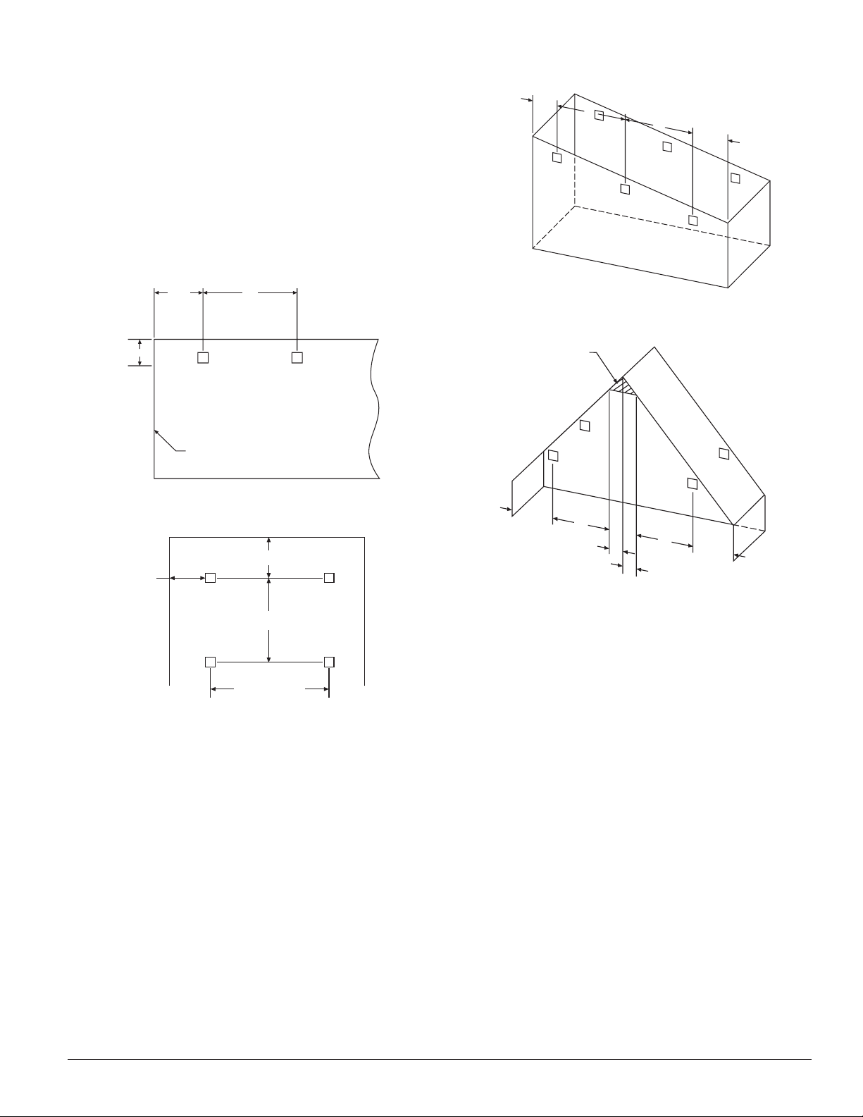
Figure 1. Spacing for smooth ceiling (side view):
Figure 3. Sloped ceiling (shed type):
C0538-00
Figure 4. Sloped ceiling (peaked type):
Figure 2. Spacing for smooth ceiling (top view):
In the case of peaked or sloped ceilings, codes may specify
spacing of detectors by using horizontal spacing from the
peak of the roof or ceiling. Figures 3 and 4 show the spacing for both the shed type and peaked type sloped ceilings
On smooth ceilings, beam smoke detectors should generally be mounted between 12 and 18 inches from the ceiling.
In many cases, however, the location and sensitivity of the
detectors shall be the result of an engineering evaluation
that includes the following: structural features, size and
shape of the room and bays, occupancy and uses of the
area, ceiling height, ceiling shape, surface and obstructions,
ventilation, ambient environment, burning characteristics
of the combustible materials present, and the configuration
of the contents in the area to be protected.
D400-18-00 3 I56-494-13R
C0536-00
C0539-00
Mounting Locations
Beam detectors require a stable mounting surface for
proper operation. A surface which moves, shifts, vibrates,
C0537-00
or warps over time will cause false alarm or trouble condi
tions. Initial selection of a proper mounting surface will
eliminate false alarms and nuisance trouble signals.
Mount the detector on a stable mounting surface, such as
brick, concrete, a sturdy load-bearing wall, support col
umn, structural beam, or other surface that is not expected
to experience vibration or movement over time. DO NOT
MOUNT the beam detector on corrugated metal walls,
sheet metal walls, external building sheathing, external
siding, suspended ceilings, steel web trusses, rafters, nonstructural beam, joists, or other such surfaces.
PRINTED IN MEXICO
Page 4
Concrete
or Bric
k
Good Mounting
Surface
Poor Mounting
Surface
Sheet
Metal
Poor Mounting
Surface
Good Mounting
Surface
Figure 5. Good and poor mounting surfaces:
C0540-00
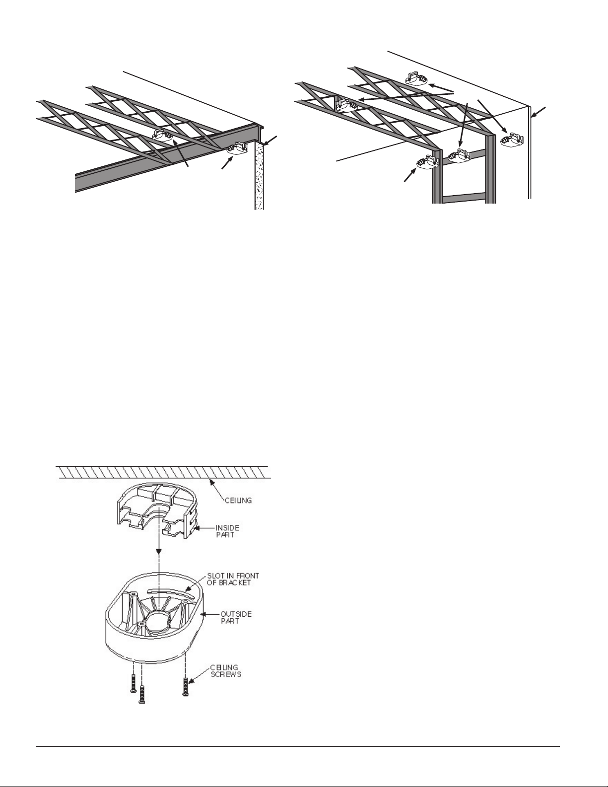
Mounting Brackets
Install a ceiling or wall bracket for both the receiver and
transmitter so that when mounted, the receiver and the
transmitter will be at approximately the same height. Each
ceiling bracket is composed of two parts that should be
assembled with inside part between the ceiling and outside part as shown in Figure 5. The brackets should be
mounted so that the slot in the front of each bracket is
facing the other bracket. Mount the brackets only on solid
structures of the building. To avoid unwanted alarms due
to wall movement, do not mount to flexible walls, such as
sheet metal walls (see MOUNTING LOCATIONS). Mount
brackets with a separation of at least 30 feet but not more
than 330 feet.
Figure 6. Ceiling mount bracket assembly:
Wiring Installation Guidelines
Always install all wiring in compliance with the National
Electrical Code, and/or the applicable local codes, and any
special requirements of the local authority having jurisdiction. Proper wire gauges and suitable means for strain relief
should be used. The conductors used to connect beam
smoke detectors to control panels and accessory devices
should be color-coded to reduce the likelihood of wiring
errors. Improper connections can prevent a system from
responding properly in the event of a fire.
Installation wire used for the beam detector shall be no
smaller than 18 gauge (1.0 square mm). For best sys
tem performance, all wiring should be twisted pair and
installed in separate grounded conduit. Do NOT mix fire
system wiring in the same conduit as any other electrical
wiring. Shielded cable may be used to provide additional
protection against electrical interference.
When installing the beam smoke detector in applica
tions where flexible conduit will be used the BMB Beam
Mounting Bracket kit must be installed with the cable
before wiring the unit, as per the instructions supplied
with the kit.
-
-
For wiring, first remove the pre-cut insulation from the con
ductor to be connected, then use a wire nut to connect the
detector wire to the field wire. If the insulation has been
removed from any unused conductors, make sure they are
terminated properly to avoid short circuits. The transmitter can be wired in one of two ways. Figure 7 shows the
transmitter permanently connected to the receiver. In this
case the transmitter receives its power along with communication for the alignment aid through the connecting
pair of wires. Figure 8 shows an alternative wiring con-
C0741-00
figuration in which the transmitter receives its power from
a remote power source. Temporary wiring can be installed
for the communication needed for transmitter alignment
D400-18-00 4 I56-494-13R
PRINTED IN MEXICO
-
Page 5

CLASS A
RETURN LOOP
INITIATING
LOOP
POWER
TO
DETECTORS
LISTED PANEL
TRANSMITTER
BLUE GREEN
ORANGE
GREEN
BLACK
RED-WHITE
STRIPE
WHITE
WHITE-BLACK
STRIPE
GRAY
VIOLET
WHITE-VIOLET
STRIPE
BROWN
WHITE-
YELLOW
STRIPE
WHITE-RED
STRIPE
TRANSMITTER
ORANGE
GREEN
BLACK
RED-WHITE
STRIPE
WHITE
WHITE-BLACK
STRIPE
GRAY
VIOLET
WHITEVIOLET
STRIPE
BROWN
WHITE-
YELLOW
STRIPE
WHITE-
RED
STRIPE
RECEIVER RECEIVER
EOL
RESISTOR
LISTED
EOL POWER
SUPERVISION
RELAY MODULE
(SHOWN ENERGIZED)
BLUE GREEN
NOTE: FOR PROPER
SUPERVISION, AN
EOL RELAY MUST
BE USED.
Figure 7. Transmitter permanently wired to receiver:
CLASS A
RETURN LOOP
INITIATING
LOOP
POWER
TO
DETECTORS
LISTED PANEL
LISTED
REMOTE
POWER
SOURCE
POWER
INPUTS TO
TRANSMITTER ARE
NONPOLAR
TRANSMITTER
BLUE
GREEN
WHITE
BROWN
BLACK RED
ORANGE
GREEN
BLACK
RED-WHITE
STRIPE
WHITE
WHITE-BLACK
STRIPE
GRAY
VIOLET
WHITE-VIOLET
STRIPE
BROWN
WHITE-
YELLOW
STRIPE
WHITE-RED
STRIPE
TRANSMITTER
BLUE
GREEN
BLACK
RED
ORANGE
GREEN
BLACK
RED-WHITE
STRIPE
WHITE
WHITE-BLACK
STRIPE
GRAY
VIOLET
WHITEVIOLET
STRIPE
BROWN
WHITE-
YELLOW
STRIPE
WHITE-
RED
STRIPE
RECEIVER RECEIVER
EOL
RESISTOR
LISTED
EOL POWER
SUPERVISION
RELAY MODULE
(SHOWN ENERGIZED)
OPTIONAL TEMPORARY WIRING FOR
TRANSMITTER ALIGNMENT AID.
NOTE: FOR PROPER
SUPERVISION, AN
EOL RELAY MUST
BE USED.
C0541-00
Figure 8. Transmitter powered separately:
D400-18-00 5 I56-494-13R
C0542-00
PRINTED IN MEXICO
Page 6

aid. If the remote power configuration is used, the remote
6424 REMOTE OUTPUTS
ORANGE
AUX (–)
TROUBLE
SIGNAL
WHITE-GREEN STRIPE
ALARM
SIGNAL
WHITE-BROWN STRIPE
POWER (+)
POWER (–)
1
2
4
3
5
RTS451 OR RTS451KEY
REMOTE TEST STATIO
N
6424
TEST
BLUE
RESET
YELLOW
AUX (–)
ORANGE
ALARM SIGNAL
WHITE-BROWN STRIPE
WARNING
Additional
Lens
Receiver
power source must comply with all codes and directives
of the Authority Having Jurisdiction. NOTE: The transmitter should be permanently wired to the receiver (Figure
7) whenever possible to allow the alignment LEDs on the
transmitter to be used during the alignment procedure.
Figure 9 shows the remote outputs for trouble and alarm,
while Figure 10 shows the connection necessary for using
the remote test station (RTS451 or RTS451KEY).
NOTE: The test coil which is shipped with the RTS451 and
RTS451KEY is not used on the 6424 Beam Smoke
Detector.
Figure 9. Remote annunciators:
C0543-00
Figure 10. Remote Test Station:
Disconnect the power from the initiating device circuits
before installing the detectors.
1. The clear protective film and warning label on the
smoked lens of both the receiver and transmitter MUST
be removed before they can operate. To remove them,
grasp a free corner of the clear protective film and pull
so that both the film and the warning label are peeled
from the smoked glass lens.
2. Mount brackets and connect cables properly as detailed
above.
3. Insert the flange of the detector mounting bracket into
the keyed hole of the wall or ceiling mounting bracket.
Slide the detector forward into position. The detector
should now hang from the bracket.
4. Insert the correct screw and washer combination (either
wall or ceiling mount) through the slot and into the hole
of the mounting bracket flange. Tighten the screw until
almost snug. The detector should still turn easily in both
directions.
5. Open the sliding access door on the back of the unit.
6. Plug cable connector into slot in metal barrier, observing
proper orientation (see Figures 14 and 15).
7. Repeat for the other unit.
8. IMPORTANT: If the detector spacing is between 30 and
60 feet, the additional filter (included) must be attached
to the receiver lens. Peel the protective backing off the
filter and install as shown in Figure 11.
C0544-00
Installation
Reference Figures 11 through 17 for installation, alignment, and maintenance.
Figure 11. Additional filter required for installations
with 30 to 60 Ft. spacing only:
C0545-00
Alignment
Figure 16. Front View Transmitter and Receiver
D400-18-00 6 I56-494-13R
PRINTED IN MEXICO
Page 7

Figure 12. Wall mounting:
HORIZONTAL
ADJUSTMENT SCREW
(#10-24 x 1-3/8 in.)
METAL WASHER
MOUNTING HUB
MOUNTING HUB
ALIGNMENT
LEDs
STATUS
LEDs
(RECEIVER ONLY)
BEAM LENS
HOLE PLUG
ALIGNMENT ADJUST
POTENTIOMETER
(RECEIVER ONLY)
CABLE EGRESS
HOLE PLUG. USED TO
PLUG UNUSED HOLE.
VERTICAL
ADJUSTMENT
SCREWS (2)
“U” BRACKET
WALL MOUNTING
BRACKET
MOUNTING HOLE
PLASTIC WASHER
Figure 13. Ceiling mounting:
C0546-00
D400-18-00 7 I56-494-13R
C0547-00
PRINTED IN MEXICO
Page 8

Figure 14. Rear view receiver:
ACCESS DOOR
CONNECTOR
16 CONDUCTOR
CABLE
RESET SWITCH
30
55
SENSITIVITY
SELECT SWITCH
N
A
ALIGNMENT
MODE SWITCH
ACCESS DOOR
CONNECTO
R
6 CONDUCTOR
CABLE
A
N
ALIGNMENT
MODE SWITC
H
SW1
L
S
RANGE
SELECT SWITCH
SW2
C0548-00
Figure 15. Rear view transmitter:
C0549-00
D400-18-00 8 I56-494-13R
PRINTED IN MEXICO
Page 9

4 RED LEDs USED
FOR ALIGNMENT
GREEN: FLASHES APPROXIMATELY EVERY
2 SECONDS IF POWERED UP AND
SENSING A SAFE CONDITION.
YELLOW: TURNS ON WHILE A TROUBLE
CONDITION EXISTS.
RED: TURNS ON IF AN ALARM
CONDITION IS SENSED.
LATCHES ON UNTIL RESET.
NOT USED
RECEIVER:
TRANSMITTER:
ALIGNMENT LEDs
ALIGNMENT ADJUST POT
(RECEIVER ONLY)
MAX. MIN.
CAUTION
Figure 17. Alignment adjust pot (receiver only):
C0550-00
accomplished by two individuals. This allows the adjust
ment of the gain pot on the receiver during alignment of the
transmitter without the need for several trips back and forth
between the transmitter and receiver.
A) ALIGNMENT SETUP:
1) At the transmitter, select the proper range using the
range selection switch (SW2) on the transmitter.
Short Range (S): 30 to 100 feet
Long Range (L): 100 to 330 feet
2) If the transmitter is directly wired to the receiver (Figure
7), slide the alignment switch (SW1) on the transmitter
to the A (align) position (see Figure 15). Point the transmitter directly at the receiver, then go to step 5.
3) If the transmitter is wired directly to a power supply, it
should be temporarily wired to the receiver if possible
(see Figure 8). NOTE: Temporarily wiring the transmitter to the receiver is beneficial because it activates the
alignment LEDs on the transmitter to allow alignment
of the transmitter without having to look at the alignment LEDs on the receiver.
-
4) If the transmitter is not wired directly to the receiver,
make sure the SW1 switch remains in the N (normal)
position (see Figure 15) before going to step 5. Point
the transmitter directly at the receiver.
5) At the receiver, select the proper sensitivity using the
switch on the back of the receiver (see Figure 14). The
sensitivity selected depends on the separation of the
transmitter and receiver. The sensitivities and ranges
shown are in accordance with UL standard 286, Smoke
Detectors for Fire Protective Signaling Systems.
SENSITIVITY DISTANCE
30% 30 to 92 feet
C0551-00
30% or 55% 92 to 178 feet
(30% is more sensitive)
55% 178 to 330 feet
The clear protective film and warning label on the smoked
lens of both the receiver and transmitter MUST be removed
before they can operate.
6) Using a small standard screwdriver, make sure the alignment adjust pot on the receiver (see Figure 17) is turned
fully counterclockwise, looking at it from the bottom
(maximum gain). The alignment adjust pot changes the
The alignment of the 6424 is divided into three steps:
alignment setup, alignment of the transmitter, and alignment of the receiver. It is necessary for all three steps to
be executed properly to ensure proper alignment of the
product. If the 6424 is mounted to a recommended surface
(see MOUNTING LOCATIONS) and alignment procedures
are executed properly, false alarms and nuisance trouble
gain of the amplifier to compensate for differences in
separation between the receiver and transmitter and has
no effect on the detector sensitivity.
7) Turn on power to the system.
8) Slide the alignment switch on the receiver to A (see
Figure 14). The yellow trouble LED should light to
signals will be avoided. The alignment procedure is best
D400-18-00 9 I56-494-13R
PRINTED IN MEXICO
Page 10

indicate alignment mode, but the trouble relay will
SENSITIVITY IN %/FT VS DISTANCE
ASSUMING UNIFORM SMOKE DISTRIBUTION
DISTANCE (FEET
)
OBSCURATION (%/FT)
30405060708090
100
11
0
120
130
140
150
160
170
180
190
200
210
220
230
240
250
260
270
280
290
300
310
320
330
1.3
1.2
1.1
1
0.9
0.8
0.7
0.6
0.5
0.4
0.3
0.2
0.1
= 30% Sensitivity Setting
= 55% Sensitivity Settin
g
not activate. If the receiver is left in the alignment
mode for more than an hour, the trouble relay will
activate.
9) Point the receiver directly at the transmitter.
B) RECEIVER ALIGNMENT PROCEDURE:
1) Align the receiver by slowly moving it back and forth,
and up and down until all four LEDs light. (NOTE: If
it is impossible to get all four LEDs to light, the trans
mitter may need to be adjusted. Go to the transmitter
and align it so that all four LEDs light, and then go
back to the receiver and continue with step 2.)
2) Adjust the alignment adjust pot until only three align
ment LEDs are lit.
5) Verify that three alignment LEDs are lit and switch
back to NORMAL MODE (N) at the receiver. It is
important that three alignment LEDs are on (not
four) when leaving alignment mode. This ensures
that the amplifier is not saturated with signal and
will be capable of detecting smoke within its sensitiv
ity limits. Wait at least one minute before continuing.
Do not block or disturb the beam while it is calibrating. Any interference could cause a trouble signal. If
there is a trouble signal during this period, switch the
receiver back to ALIGN MODE to make sure that only
-
three LEDs are lit. Switch back to NORMAL MODE
and wait again. If three alignment LEDs are not on,
repeat the transmitter alignment procedure.
6) When the detector has completed it’s self-calibration,
-
the green (normal) operation LED will flash every two
or three seconds. Alignment is now complete.
-
3) Further align the receiver by slowly moving it back
and forth, and up and down, trying to get all four
LEDs to light.
Sensitivity
Total obscuration can be converted to percent per foot,
assuming uniform smoke density for the entire length of
the beam. The chart below converts total obscuration to
REPEAT STEPS 2 AND 3 UNTIL IT IS IMPOSSIBLE TO
percent per foot at both 30% and 55% sensitivity settings.
GET MORE THAN THREE LEDs TO LIGHT. (NOTE:
If steps 2 and 3 are carefully executed, it should take
two to five tries to align the receiver.)
4) Carefully tighten the horizontal adjustment screws
first and then the two vertical adjustment screws on
the receiver bracket, making sure all three alignment
LEDs remain lit.
C) TRANSMITTER ALIGNMENT PROCEDURE:
1) Slowly move the transmitter back and forth, and up
and down, trying to get all four LEDs to light.
2) If four LEDs light, adjust the alignment adjust pot on
the receiver until only three alignment LEDs are on.
REPEAT STEPS 1 AND 2 UNTIL IT IS IMPOSSIBLE TO
GET MORE THAN THREE LEDs TO LIGHT. (NOTE:
If steps 1 and 2 are carefully executed, it should take
between two and five tries to achieve this.)
3) When it is impossible to get more than three LEDs
to light, carefully tighten the horizontal adjustment
screws and then the vertical adjustment screws on the
transmitter bracket, making sure all three alignment
LEDs stay lit.
4) Slide the alignment switch on the transmitter to the
NORMAL MODE (N) position (see figure 15) and
disconnect any temporary wiring. Carefully close the
door on the transmitter and go to the receiver.
D400-18-00 10 I56-494-13R
Sensitivity Testing
NOTE: Before testing, notify the proper authorities that the
smoke detector system is undergoing maintenance,
and therefore the system will be temporarily out
of service. Disable the zone or system undergoing
maintenance to prevent unwanted alarms.
Detectors must be tested after installation and following
periodic maintenance. The sensitivity of the 6424 may be
tested as follows:
PRINTED IN MEXICO
C0552-00
Page 11

NOTE: Before testing the detector, check for the presence
of the flashing green LED at the receiver, making
sure not to disturb or block the beam. If it does not
flash and the detector is not in trouble or alarm,
power has been lost to the detector (check the wiring).
A. Calibrated Test Filter
1. Test the detector at the receiver.
2. Use the proper side of the test card depending on the
sensitivity setting (55 or 30) of the detector.
If the detector is not in trouble and the unit fails to alarm,
check all related wiring. Once the proper wiring is con
firmed, perform the above calibrated test filter procedure.
If the unit still fails to alarm it should be returned for
repair.
Maintenance
NOTE: Before cleaning the detector lenses, notify the
proper authorities that the smoke detector system
is undergoing maintenance, and therefore the system will be temporarily out of service. Disable the
zone or system undergoing maintenance to prevent
unwanted alarms.
3. Place the NO ALARM section of the test filter over the
receiver lens. The green LED should continue to pulse
and the detector should not alarm after 15 seconds.
4. Place the ALARM section of the test filter over the
lens. The detector should alarm within 15 seconds.
5. The detector can be reset with the local reset, remote
reset, or by momentarily interrupting the power.
6. Notify the proper authorities that the system is back
on line.
Detectors that fail to alarm should be returned for repair.
Units that alarm during the non-alarm test (step 3) should
be cleaned and tested again before being returned. Follow
the maintenance instructions for cleaning.
B. Remote Test Switch
The remote test station, RTS451, can be used with the
6424 beam smoke detector. Follow instructions included
with the test station for proper use. See Figure 9 (Remote
Test Station) for wiring diagram.
1. Carefully clean the lenses of both the receiver and the
transmitter. A damp soft cloth with a mild soap may be
used. Avoid products with solvents or ammonia.
2. After the lenses are clean, switch the receiver to the
align mode. If three and only three alignment LEDs
turn on, slide the align switch back to normal mode
and wait approximately one minute for self calibration.
The green LED should pulse after the calibration time. If
more or fewer LEDs turn on in align mode, see the Beam
Alignment Instructions on page 9 for realignment.
3. Notify the proper authorities that the system is back on
line.
Special Note Regarding Smoke Detector Guards
Smoke detectors are not to be used with detector guards
unless the combination has been evaluated and found
suitable for that purpose.
D400-18-00 11 I56-494-13R
PRINTED IN MEXICO
Page 12

Please refer to insert for the Limitations of Fire Alarm Systems
Three-Year Limited Warranty
System Sensor warrants its enclosed smoke detector to be free from
defects in materials and workmanship under normal use and service for a
period of three years from date of manufacture. System Sensor makes no
other express warranty for this smoke detector. No agent, representative,
dealer, or employee of the Company has the authority to increase or alter
the obligations or limitations of this Warranty. The Company’s obliga
tion of this Warranty shall be limited to the repair or replacement of any
part of the smoke detector which is found to be defective in materials or
workmanship under normal use and service during the three year period
commencing with the date of manufacture. After phoning System Sensor’s
toll free number 800-SENSOR2 (736-7672) for a Return Authorization
number, send defective units postage prepaid to: System Sensor, Repair
FCC Statement
This device complies with part 15 of the FCC Rules. Operation is subject to the following two conditions: (1) This device may not cause harmful inter
ference, and (2) this device must accept any interference received, including interference that may cause undesired operation.
Note: This equipment has been tested and found to comply with the limits for a Class B digital device, pursuant to Part 15 of the FCC Rules. These
limits are designed to provide reasonable protection against harmful interference in a residential installation. This equipment generates, uses and
canradiate radio frequency energy and, if not installed and used in accordance with the instructions, may cause harmful interference to radio commu
nications. However, there is no guarantee that interference will not occur in a particular installation. If this equipment does cause harmful interference
to radio or television reception, which can be determined by turning the equipment off and on, the user is encouraged to try to correct the interference
by one or more of the following measures:
– Reorient or relocate the receiving antenna.
– Increase the separation between the equipment and receiver.
– Connect the equipment into an outlet on a circuit different from that to which the receiver is connected.
– Consult the dealer or an experienced radio/TV technician for help.
D400-18-00 12 I56-494-13R
©2004 System Sensor PRINTED IN MEXICO
Department, RA #__________, 3825 Ohio Avenue, St. Charles, IL 60174.
Please include a note describing the malfunction and suspected cause
of failure. The Company shall not be obligated to repair or replace units
which are found to be defective because of damage, unreasonable use,
modifications, or alterations occurring after the date of manufacture. In
-
no case shall the Company be liable for any consequential or incidental
damages for breach of this or any other Warranty, expressed or implied
whatsoever, even if the loss or damage is caused by the Company’s neg
ligence or fault. Some states do not allow the exclusion or limitation of
incidental or consequential damages, so the above limitation or exclusion
may not apply to you. This Warranty gives you specific legal rights, and
you may also have other rights which vary from state to state.
-
-
-
 Loading...