

Page 1
INSTALLATION AND MAINTENANCE INSTRUCTIONS
546-8000 Cover Tamper Switch
For use with System Sensor Pressure Switches:
EPS10-1, EPS10-2, EPS40-1, EPS40-2, EPS120-1, EPS120-2
Specifications
Contact Ratings: 5A @ 125/250 VAC
2.5A @ 6/12/24 VAC
Operating Temperature Range: -40° to +160°F (-40° to +71°C)
Shipping Weight: 0.115 lbs.
NOTICE: This manual should be left with the owner/user
of this equipment.
General Information
The System Sensor 546-8000 cover tamper switch mounts
to EPS series pressure switches to monitor removal of the
cover. Cover removal produces a switch output. The unit
will reset when the product cover is reinstalled.
Wiring Instructions
1. Remove the pressure switch cover using the security
wrench provided with the pressure switch.
2. Attach the cover switch with the two screws provided
(see Figure 1).
3. Route wires away from the pressure switch mechanism.
4. Wire the circuit as shown in Figures 2, 3, or 4, or as required by the installation requirements and as approved
by the authority having jurisdiction. Clip the unused
wire from the tamper switch and use the wire nut to protect from shorting.
5. Perform the required system tests and include the cover
tamper switch in the test by alternately replacing and removing the cover to produce the desired circuit effects.
6. After testing, secure the cover with the security wrench.
A Division of Pittway
3825 Ohio Avenue, St. Charles, Illinois 60174
1-800-SENSOR2, FAX: 630-377-6495
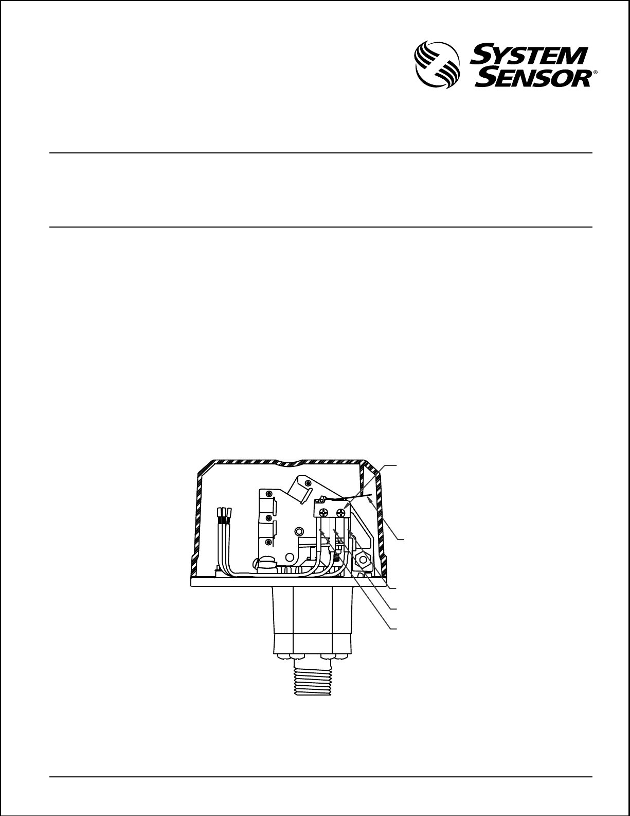
Figure 1. Wire routing inside EPS Series pressure switch:
C
A
SWITCH
B
SCREWS
SWITCH
ARM
NORMALLY
CLOSED
NORMALLY
OPEN
COM
A78-2616-01
D770-14-00 1 I56-919-02
Page 2
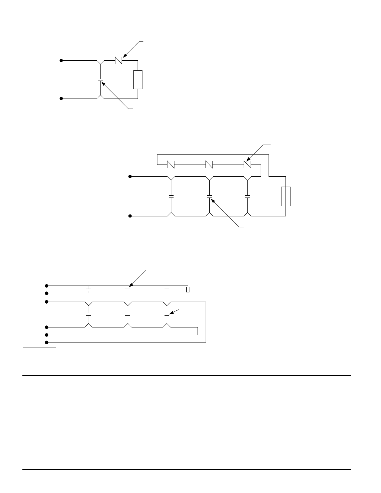
Figure 2. Class B initiating circuit with single device:
COVER
TAMPER
SWITCH
1
CONTROL
PANEL
2
END OF LINE
DEVICE
INITIATING
DEVICE
A78-2617-00
Figure 3. Class B initiating circuit with multiple devices:
1
CONTROL
PANEL
2
Figure 4. Class A 4-wire initiating circuit with multiple devices:
INITIATING
DEVICES
COVER
TAMPER
SWITCHES
END OF LINE
DEVICE
A78-2618-00
COVER
TAMPER
SUPERVISORY ZONE
CONTROL
PANEL
SWITCHES
Three-Year Limited Warranty
System Sensor warrants its enclosed cover tamper switch to be free from
defects in materials and workmanship under normal use and service for a
period of three years from date of manufacture. System Sensor makes no
other express warranty for this cover tamper switch. No agent, representative, dealer, or employee of the Company has the authority to increase or
alter the obligations or limitations of this Warranty. The Company’s obligation of this Warranty shall be limited to the repair or replacement of any
part of the cover tamper switch which is found to be defective in materials
or workmanship under normal use and service during the three year period commencing with the date of manufacture. After phoning System
Sensor’s toll free number 800-SENSOR2 (736-7672) for a Return Authorization number, send defective units postage prepaid to: System Sensor,
END OF LINE
DEVICE
INITIATING
DEVICES
A78-2619-00
Repair Department, RA #__________, 3825 Ohio Avenue, St. Charles, IL
60174. Please include a note describing the malfunction and suspected
cause of failure. The Company shall not be obligated to repair or replace
units which are found to be defective because of damage, unreasonable
use, modifications, or alterations occurring after the date of manufacture.
In no case shall the Company be liable for any consequential or incidental
damages for breach of this or any other Warranty, expressed or implied
whatsoever, even if the loss or damage is caused by the Company’s negligence or fault. Some states do not allow the exclusion or limitation of incidental or consequential damages, so the above limitation or exclusion may
not apply to you. This Warranty gives you specific legal rights, and you
may also have other rights which vary from state to state.
D770-14-00 2 I56-919-02
© System Sensor 1996
 Loading...