

Page 1
INSTALLATION AND MAINTENANCE INSTRUCTIONS
Cover Tamper Switch
Specifications
Contact Ratings: 5.0A @ 125/250 VAC
2.5A @ 24 VDC
Overall Dimensions: 11/4˝H x 2˝W x 3/4˝D
Operating Temperature Range: 32° to 120°F (0° to 49°C)
Shipping Weight: 0.025 lb.
A Division of Pittway
3825 Ohio Avenue, St. Charles, Illinois 60174
1-800-SENSOR2, FAX: 630-377-6495
NOTICE: This manual should be left with the owner/user
of this equipment.
CAUTION
Do not leave unused wires exposed. Do not use in potentially explosive atmospheres.
General Information
This cover tamper switch mounts to all System Sensor
WFD, WFDT, OSY2 and PIBV2 terminal block units. Cover
removal produces a switch output. The unit will reset when
the product cover is reinstalled.
Installation Guidelines
Before installing any cover tamper switch, be thoroughly
familiar with:
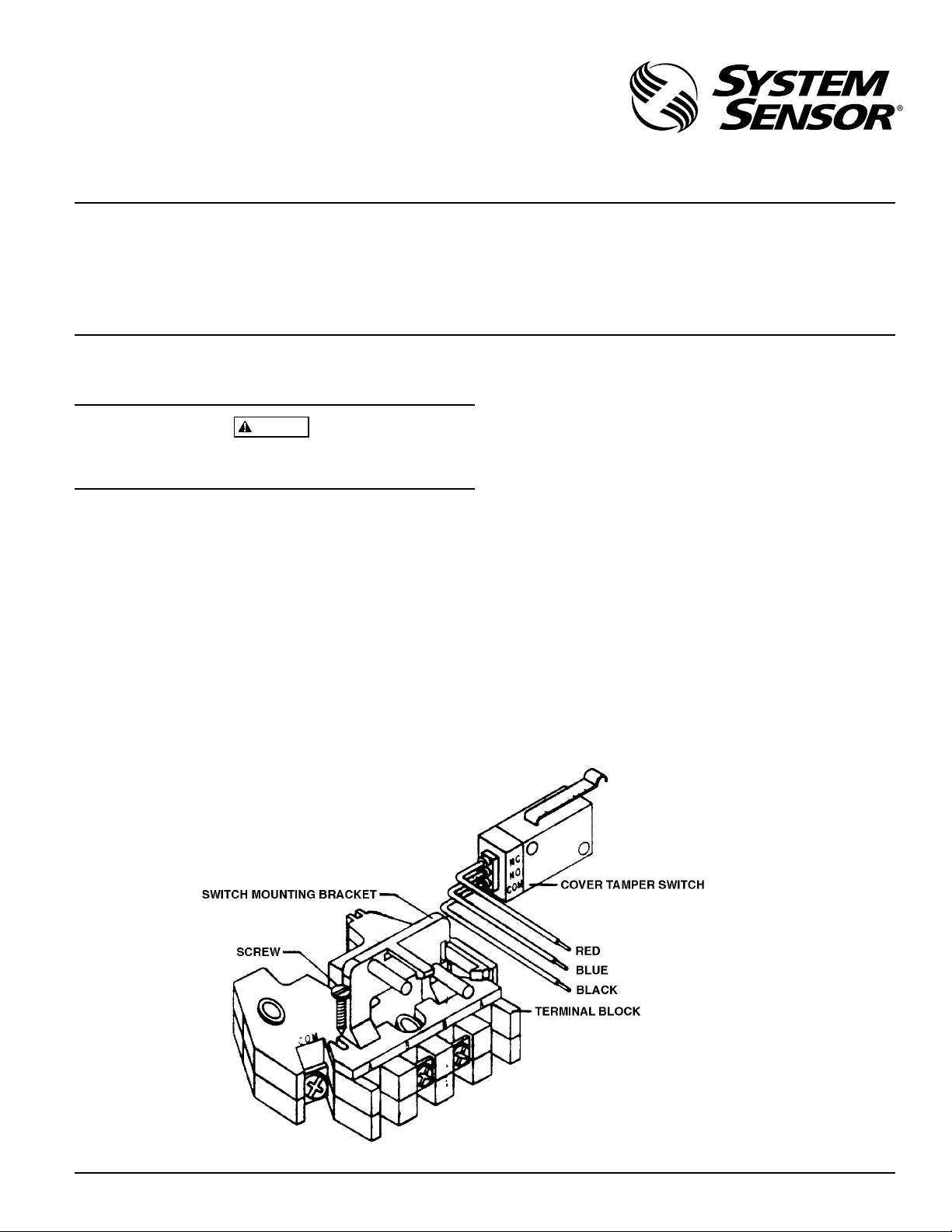
Figure 1. Assembly Diagram:
NFPA 72: National Fire Alarm Code
NFPA 13: Installation of Sprinkler Systems, specifically
section 3.17.
NFPA 25: Inspection, Testing and Maintenance of Sprin-
kler Systems, specifically chapters 4 and 5.
Other applicable NFPA standards, local codes and the requirements of the authority having jurisdiction.
Failure to follow these directions may result in failure of the
device to report an alarm or trouble condition. System Sensor is not responsible for devices that have been improperly
installed, tested or maintained.
Mounting Instructions
1. Install switch mounting bracket onto terminal block us-
ing the 2 screws provided, shown in Figure 1.
2. Snap the switch onto the switch mounting bracket in po-
sition shown in Figure 1.
A78-1661-00
D770-05-00 1 I56-403-03
Page 2
WARNING
High voltage. Electrocution hazard. Do not handle live AC
wiring or work on a device to which AC power is applied.
Doing so may result in severe injury of death.
Field Wiring
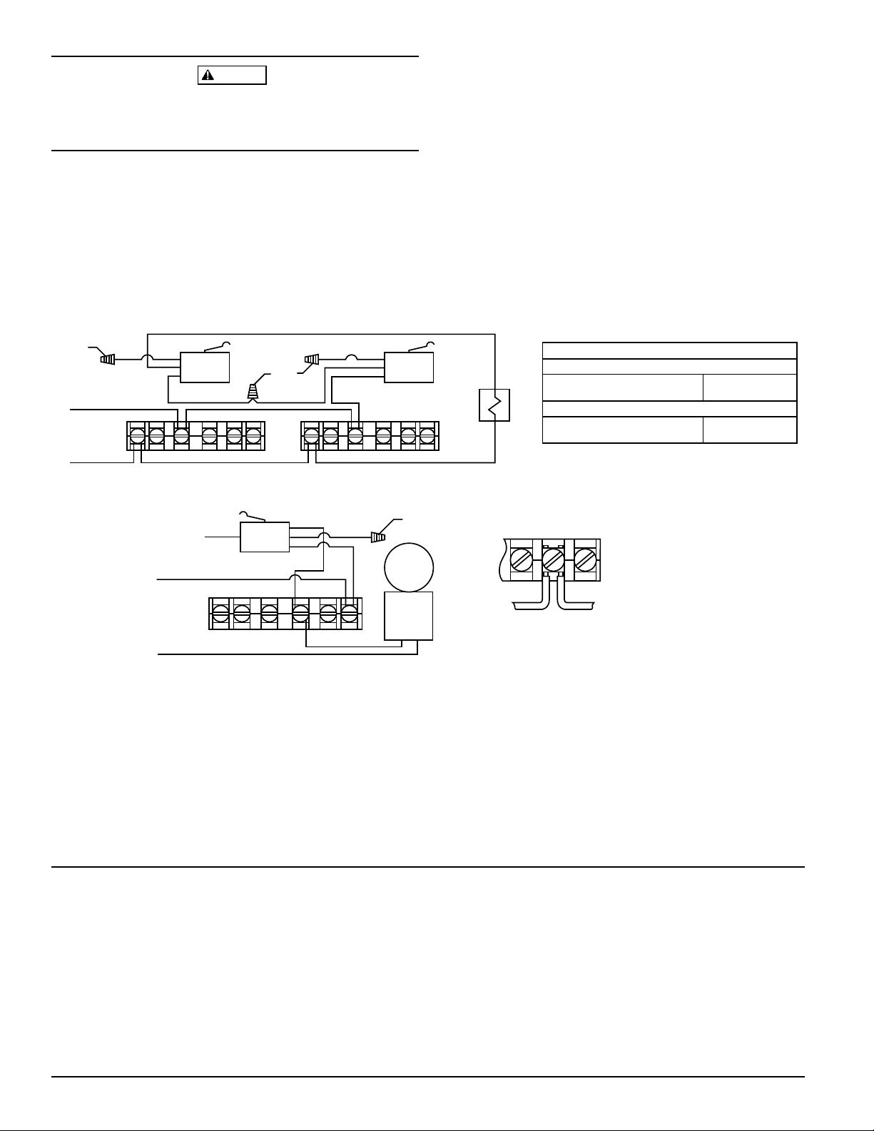
1) Wire as required per wiring diagram (Figure 2), placing
the stripped wire lead under the correct terminal plate.
Extra wire lead should be clipped and terminated with a
wire nut to avoid shorting to housing.
Figure 2. Field Wiring:
Blue
Wire
Nut
to nonsilenceable
initiating zone
of listed FACP
Red
COM COM
NC
NO
COM
BB
Typical Fire Alarm Control Panel Connection
Red
Wire
Nut
BlackBlueBlack
COM COM
BB
AAAA
NC
NO
COM
NOTE: Where one wire already exists under the terminal
plate, connect the cover tamper wire under the opposite side of the terminal plate.
2) When connected to a listed sprinkler/fire alarm control
panel, the initiating circuit must be non-silenceable.
Wire Code:
Cover Tamper Switch:
(Non Alarm
Condition)
(Cover Off)
end-of-line
resistor
Waterflow or Supervisory Switch:
Com to B = Open Circuit
Com to A = Closed Circuit
Black / Blue: Open
Black / Red: Closed
Cover
Tamper
Switch
to power
source
compatible
with bell
NC
NO
COM
Red
B
Blue
Black
A
COM
Wire
Nut
local
bell
Break wire as shown for
supervision of connection.
DO NOT allow stripped wire
leads to extend beyond
switch housing. DO NOT
loop wires.
Typical Local Bell Connection
NOTE:
A78-1662-01
Local bell will activate
when cover is removed.
Operational Testing
Always notify a central station monitoring waterflow or supervisory switch alarms before repairing, maintaining, or
testing cover tamper switch devices.
Three-Year Limited Warranty
System Sensor warrants its enclosed cover tamper switch to be free from
defects in materials and workmanship under normal use and service for a
period of three years from date of manufacture. System Sensor makes no
other express warranty for this cover tamper switch. No agent, representative, dealer, or employee of the Company has the authority to increase or
alter the obligations or limitations of this Warranty. The Company’s obligation of this Warranty shall be limited to the repair or replacement of any
part of the cover tamper switch which is found to be defective in materials
or workmanship under normal use and service during the three year period commencing with the date of manufacture. After phoning System
Sensor’s toll free number 800-SENSOR2 (736-7672) for a Return Authorization number, send defective units postage prepaid to: System Sensor,
D770-05-00 2 I56-403-03
1) Replace the cover and tighten the security screws with
the security wrench. Store the wrench in a secure place.
2) Verify that circuit has reset by checking FACP.
Repair Department, RA #__________, 3825 Ohio Avenue, St. Charles, IL
60174. Please include a note describing the malfunction and suspected
cause of failure. The Company shall not be obligated to repair or replace
units which are found to be defective because of damage, unreasonable
use, modifications, or alterations occurring after the date of manufacture.
In no case shall the Company be liable for any consequential or incidental
damages for breach of this or any other Warranty, expressed or implied
whatsoever, even if the loss or damage is caused by the Company’s negligence or fault. Some states do not allow the exclusion or limitation of incidental or consequential damages, so the above limitation or exclusion may
not apply to you. This Warranty gives you specific legal rights, and you
may also have other rights which vary from state to state.
© System Sensor 1996
 Loading...