

Page 1

INSTALLATION AND MAINTENANCE INSTRUCTIONS
WARNING
I56-5151-001
5151 Plug-In Heat Detector
SPECIfICATIONS
Height: 1.64 inches (42 mm)
Diameter: 4.0 inches (102 mm)
Weight 2.8 oz. (80g)
Operating Temperature Range: 32° to 100°F (0° to 38°C)
Operating Humidity Range: 10% to 93% Relative Humidity noncondensing
Operating voltage: 8.5 to 35VDC
Standby Current: 80μA @24VDC
Alarm Current: 10mA Min. 130mA Max. (Must be limited by control panel)
Latching Alarm: Reset by momentary power interruption
Sensitivity: 135°F (57°C) Fixed or 15°F/min rate-of-rise
BEfORE INSTALLING
This detector must be installed in compliance with the control panel installation manual and meet the requirements of the authority having jurisdiction.
Inaddition, the National Fire Protection Association has published codes, standards, and recommended practices for the installation and use of detectors,
NFPA 72.
Therefore, the installer must be familiar with these requirements, with local
codes, and any special requirements of the authority having jurisdiction.
NOTICE: This manual should be left with the owner/user of this equipment.
IMPORTANT: The detector must be tested and maintained regularly following
NFPA 72 requirements. The detector should be cleaned at least once a year.
GENERAL DESCRIPTION
The 5151 is a rate-of-rise with fixed temperature alarm, conventional 2-wire
thermal detector. This detector is designed to provide open area protection
with 50-foot spacing capability as approved by UL 521, RTI rating is classified
as FAST in accordance with FM 3210.
Two LEDs on each detector provide local 360° visible alarm indication. They
flash every five seconds indicating that power is applied and the detector
is working properly. The LEDs latch on in alarm. LEDs will be off when a
trouble condition exists indicating that the detector sensitivity is outside the
listed limit. Remote LED annunciator capability is standard and may be implemented through an optional accessory RA100Z. The alarm can be reset only
by a momentary power interruption. This detector may be tested by activating
the internal reed switch with a magnet.
BASE WIRING GUIDE
Refer to the installation instructions for the plug-in detector base for electrical
specifications and wiring instructions. The base provides screw terminals for
power and remote annunciator connections.
INSTALLATION
NOTE: All wiring must conform to applicable local codes, ordinances, and
regulations.
NOTE: Verify that all detector bases are installed, that the initiating-device
circuits have been tested, and that the wiring is correct. (Refer to detector base
manual for testing procedure.)
Remove power from initiating-device circuits before installing detectors.
1. Install detectors:
a. Place the detector into the detector base.
b. Turn the detector clockwise until the detector drops into place.
c. Continue turning detector clockwise to lock it in place.
2. Tamper Resistance:
The detector bases can be made tamper resistant. When capability
is enabled, detectors cannot be removed from the base without the
use of a tool. See the detector base installation manual of the detector
base for details in using this capability.
3. After all detectors have been installed, apply power to the control unit.
4. Test the detector using the magnet as described under TESTING.
5. Reset the detector at the system control panel.
6. Notify the proper authorities that the system is back on line.
TAMPER RESISTANCE
The detector bases include a feature that, when activated, prevents removal
of the detector without the use of a tool. Refer to the installation instruction
manual of the detector base to make use of this capability.
TESTING
Before testing, notify the proper authorities that the smoke detector system is
undergoing maintenance and will temporarily be out of service. Disable the
zone or system undergoing maintenance to prevent unwanted alarms. Detectors must be tested after installation and as part of periodic maintenance. Test
5151 as follows:
NOTE: Before testing the detector, check to ensure the LEDs blink. If they do
not, the detector has lost power (check the wiring), it is defective (return it for
repair), or the detector sensitivity is outside the listed limits.
A. Test Magnet (p/n M02-04-01 or M02-09-00)
1. Place the magnet against the cover in the location designated by the
raised mark to activate the test feature (see Figure 1).
2. The LEDs should latch ON within 5 seconds indicating alarm and annunciating the panel.
B. Direct Heat Method (Hair dryer of 1000-1500 watts)
1. A hair dryer of 1000-1500 watts should be used to test the thermistor.
Direct the heat toward the thermistors, holding the heat source approximately 12 inches from the detector in order to avoid damaging the plastic
housing.
2. The LEDs on the detector should light when the temperature at the detector reaches the set point.
3. Reset the detector at the system control panel. The detector will reset
only after it has had sufficient time to cool.
Notify the proper authorities that the system is back on line.
Detectors that fail these tests should be cleaned as described under MAINTENANCE and retested. If the detectors still fail these tests, they should be
returned for repair.
MAINTENANCE
NOTE: Before cleaning notify the proper authorities that the system is undergoing maintenance, and therefore the system will temporarily be out of service. Disable the loop or system undergoing maintenance to prevent unwanted
alarms.
It is recommended that the sensor be removed from its mounting base for
easier cleaning and that sensors be cleaned at least once a year. Use a vacuum
cleaner to remove dust from the sensing chamber.
3825 Ohio Avenue, St. Charles, Illinois 60174
1-800-SENSOR2, FAX: 630-377-6495
www.systemsensor.com
SS-400-011 1 I56-5151-001
Page 2
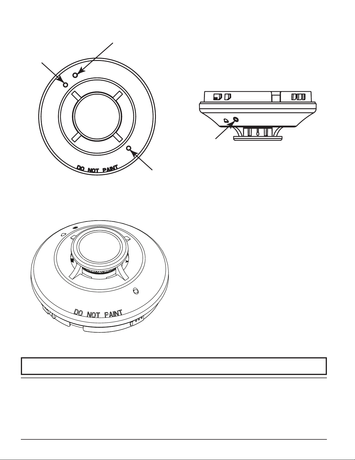
fIGURE 1. VIEWS SHOWING POSITION Of TEST MAGNET:
TEST MAGNET
LED
MARKER
LED
TEST
MAGNET
MARKER
C0152-00
fIGURE 2.
C0189-00
Please refer to insert for the Limitations of Fire Alarm Systems
System Sensor warrants its enclosed heat detector to be free from defects in materials
and workmanship under normal use and service for a period of three years from date of
manufacture. System Sensor makes no other express warranty for this heat detector. No
agent, representative, dealer, or employee of the Company has the authority to increase
or alter the obligations or limitations of this Warranty. The Company’s obligation of this
Warranty shall be limited to the repair or replacement of any part of the heat detector
which is found to be defective in materials or workmanship under normal use and service during the three year period commencing with the date of manufacture. After phoning System Sensor’s toll free number 800-SENSOR2 (736-7672) for a Return Authorization
number, send defective units postage prepaid to: System Sensor, Repair Department, RA
SS-400-011 2 I56-5151-001
©2011 System Sensor
THREE-YEAR LIMITED WARRANTY
#__________, 3825 Ohio Avenue, St. Charles, IL 60174. Please include a note describing
the malfunction and suspected cause of failure. The Company shall not be obligated to
repair or replace units which are found to be defective because of damage, unreasonable
use, modifications, or alterations occurring after the date of manufacture. In no case shall
the Company be liable for any consequential or incidental damages for breach of this
or any other Warranty, expressed or implied whatsoever, even if the loss or damage is
caused by the Company’s negligence or fault. Some states do not allow the exclusion or
limitation of incidental or consequential damages, so the above limitation or exclusion
may not apply to you. This Warranty gives you specific legal rights, and you may also
have other rights which vary from state to state.
 Loading...