

System Sensor 1451, 5451, 2451, 2451TH, 4451HT Installation And Maintenance Instructions Manual
...Page 1

INSTALLATION AND MAINTENANCE INSTRUCTIONS
1451 Plug-in Ionization
Smoke Detector
Specifications
Size
Height: 2.4 inches (6.1 cm)
Diameter: 4.0 inches (10.1 cm)
Weight: 0.6 lb. (277 g)
Operating Temperature Range: 0° to +49°C (32° to 120°F)
Operating Humidity Range: 10% to 93% Relative Humidity Non-condensing
Latching Alarm: Reset by momentary power interruption.
Before installing
Please thoroughly read the System Sensor manual I56-407,
Applications Manual for System Smoke Detectors, which
provides detailed information on detector spacing, placement, zoning, wiring, and special applications. Copies of
this manual are available at no charge from System Sensor.
(For installation in Canada refer to CAN/ULC-S524, Stan-
dard for the Installation of Fire Alarm Systems, and CEC
Part 1, Sec. 32.)
Model 1451 has been approved for marine use in dry locations by Underwriters Laboratory, Inc. The detector is to be
used in dry interior locations only.
Spacing
Spacing of 30 ft. on a smooth ceiling as per NFPA 72E.
Where conditions or response requirements vary, other
spacing may apply.
A Division of Pittway
3825 Ohio Avenue, St. Charles, Illinois 60174
1-800-SENSOR2, FAX: 630-377-6495
NOTICE: This manual should be left with the owner/user
of this equipment.
IMPORTANT: This sensor must be tested and maintained
regularly following NFPA 72 requirements. This sensor
should be cleaned at least once a year.
General Description
Model 1451 dual chamber ionization detectors utilize state-ofthe-art, unipolar sensing chambers. These detectors are designed to provide open area protection, and to be used with
compatible UL-listed control panels only. The capability of
plugging these detectors into a variety of special bases makes
them more versatile than equivalent direct-wired models.
Two LEDs on each detector light to provide a local 360° visible alarm indication. Remote LED annunciator capability
is available as an optional accessory. These detectors also
have the latching alarm feature. The alarm can be reset
only by a momentary power interruption. For testing, these
detectors have an internal magnetically activated reed
switch.
Base Selection And Wiring Guide
Refer to the installation instructions for the plug-in detector
bases for wiring instructions. System Sensor has available a
variety of detector bases for this smoke detector, including 2wire applications with and without relays and/or current limiting resistors, 4-wire and 120VAC applications. (Note: the
120VAC detector base is not available in Canada.)
All bases are provided with screw terminals for power,
ground, remote annunciator connections, and relay contact
connections, if applicable. The electrical ratings for each
detector-base combination are also included in the base installation instructions.
D400-01-01 1 I56-278-05
Technical Manuals Online! - http://www.tech-man.com
Page 2
Installation
NOTE: All wiring must conform to applicable local codes,
ordinances, and regulations.
NOTE: Verify that all detector bases are installed, that the
initiating-device circuits have been tested, and that
the wiring is correct.
CAUTION
Dust covers can be used to help limit dust entry to the detector, but they are not a substitute for removing the detector during building construction. Remove any dust covers
before placing system in service.
WARNING
Remove power from initiating-device circuits before installing detectors.
1. Install Detectors:
a. Place the detector into the detector base.
b. Turn the detector clockwise until the detector drops
into place.
c. Continue turning detector clockwise to lock it in
place.
2. Tamper-proof Feature
The detector bases include a feature that, when activated, prevents removal of the detector without the use
of a tool. See the installation instruction manual of the
detector base for details in using this feature.
3. After all detectors have been installed, apply power to
the control unit.
4. Test the detector as described under TESTING.
5. Reset the detector at the system control panel.
Testing
Before testing, notify the proper authorities that the smoke
detector system is undergoing maintenance and will temporarily be out of service. Disable the zone or system undergoing maintenance to prevent unwanted alarms.
Detectors must be tested after installation and periodic
maintenance. The 1451 may be tested as follows:
Before testing the detector, look for the presence of the
flashing LEDs. If they do not flash, either power has been
lost to the detector (check the wiring), or it is defective (return for repair).
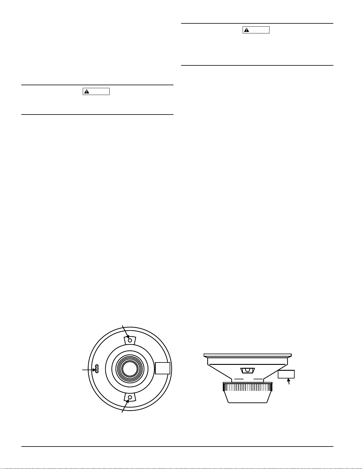
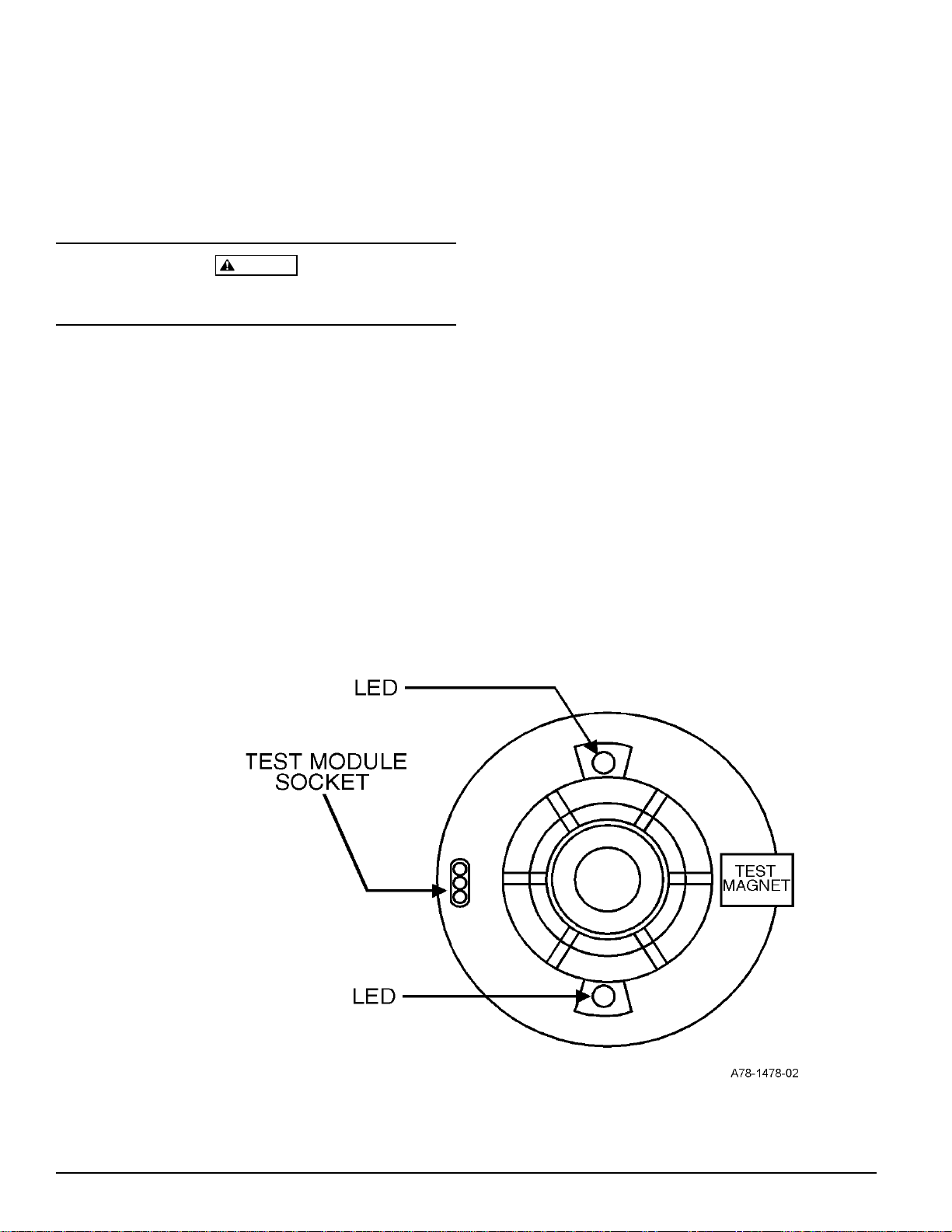
A. Test Magnet (System Sensor Model No. M02-04-00)
1. Place the magnet against the cover opposite the test
module socket. (See Figure 1.)
2. The LEDs on the detector should latch on within 30
seconds.
3. Reset the detector at the system control panel.
6. Notify the proper authorities that the system is in
operation.
Figure 1. Botom and side views showing test magnet position:
LED
TEST MODULE
SOCKET
LED
TEST
MAGNET
PAINTED
SURFACE
TEST
MAGNET
A78-1161-00
D400-01-01 2 I56-278-05
Technical Manuals Online! - http://www.tech-man.com
Page 3
B. Test Module (System Sensor Model No. MOD400R)
The MOD400 or MOD400R is used with a digital or analog voltmeter to check the detector sensitivity as described in the test module’s manual.
4. After cleaning, snap the screen into the cover, then place
the cover and screen assembly on the detector, turning
clockwise until it is locked in place.
5. Reinstall the detector.
C. Aerosol Generator (Gemini 501)
Set the generator to represent 4%/ft. to 5%/ft. obscuration as described in the Gemini 501 manual. Using the
bowl shaped applicator, apply aerosol until unit alarms.
Notify the proper authorities that the system is back on
line.
Detectors that fail these tests should be cleaned as described under MAINTENANCE and retested. If the detectors still fail these tests they should be returned for repair.
Maintenance
It is recommended that the detector be removed from its
mounting base to facilitate easier cleaning. The detector is
cleaned as follows:
NOTE: Before removing the detector, notify the proper au-
thorities that the smoke detector system is undergoing maintenance, and will temporarily be out of
service. Disable the zone or system undergoing
maintenance to prevent unwanted alarms.
6. Test the detector as described under TESTING.
7. Notify the proper authorities that the system is back on
line.
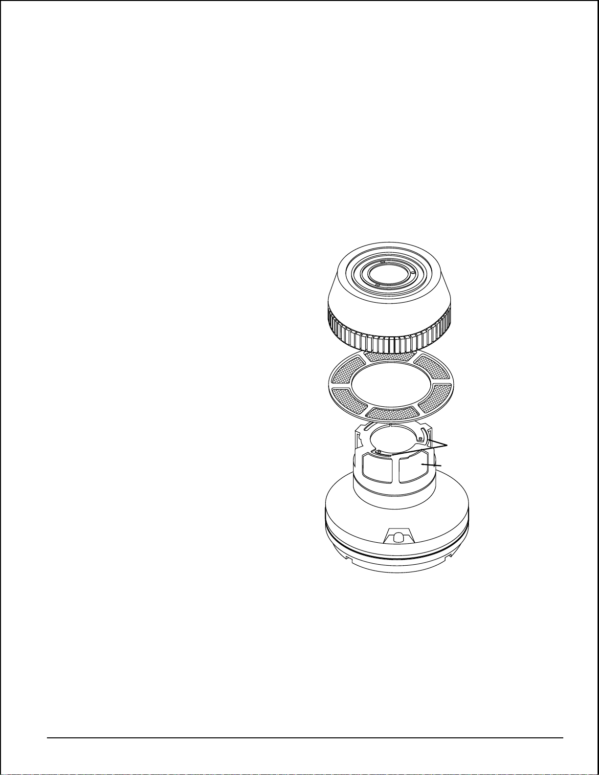
Figure 2:
REMOVABLE
COVER
FOR
CLEANING
REMOVABLE SCREEN
(P/N RS14)
1. Remove the detector screen and cover assembly by depressing the three lock prongs on the top of the cover,
rotating the cover counterclockwise, and pulling the
screen and cover assembly away from the detector. (See
Figure 2.) Usage of a System Sensor CRT400 cover removal tool is recommended.
2. Remove the screen from the cover.
3. Use a vacuum cleaner to remove dust from the screen,
the cover, and the sensing chamber.
LOCK PRONG
SENSING CHAMBER
A78-2340-00
D400-01-01 3 I56-278-05
Technical Manuals Online! - http://www.tech-man.com
Page 4

WARNING
The Limitations of Property Protection Smoke Detectors
This smoke detector is designed to activate and initiate emergency action, but will do so only when it is used in conjunction with an authorized
fire alarm system. This detector must be installed in accordance with
NFPA standard 72.
Smoke detectors will not work without power. AC or DC powered
smoke detectors will not work if the power supply is cut off.
Smoke detectors will not sense fires which start where smoke does not
reach the detectors. Smoldering fires typically do not generate a lot of
heat which is needed to drive the smoke up to the ceiling where the
smoke detector is usually located. For this reason, there may be large delays in detecting a smoldering fire with either an ionization type detector
or a photoelectric type detector. Either one of them may alarm only after
flaming has initiated which will generate the heat needed to drive the
smoke to the ceiling.
Smoke from fires in chimneys, in walls, on roofs or on the other side of a
closed door(s) may not reach the smoke detector and alarm it. A detector
cannot detect a fire developing on another level of a building quickly or at
all. For these reasons, detectors shall be located on every level and in
every bedroom within a building.
Smoke detectors have sensing limitations, too. Ionization detectors and
photoelectric detectors are required to pass fire tests of the flaming and
smoldering type. This is to ensure that both can detect a wide range of
types of fires. Ionization detectors offer a broad range of fire sensing capability but they are somewhat better at detecting fast flaming fires than
slow smoldering fires. Photoelectric detectors sense smoldering fires better
than flaming fires which have little, if any, visible smoke. Because fires develop in different ways and are often unpredictable in their growth, neither type of detector is always best, and a given detector may not always
provide early warning of a specific type of fire.
In general, detectors cannot be expected to provide warnings for fires resulting from inadequate fire protection practices, violent explosions, escaping gases which ignite, improper storage of flammable liquids like
cleaning solvents which ignite, other similar safety hazards, arson, smoking in bed, children playing with matches or lighters, etc. Smoke detectors
used in high air velocity conditions may have a delay in alarm due to dilution of smoke densities created by frequent and rapid air exchanges. Additionally, high air velocity environments may create increased dust
contamination, demanding more frequent maintenance.
Smoke detectors cannot last forever. Smoke detectors contain electronic
parts. Even though smoke detectors are made to last over 10 years, any
part can fail at any time. Therefore, smoke detectors shall be replaced after
being in service for 10 years. The smoke detector system that this detector
is used in must be tested regularly per NFPA 72. This smoke detector
should be cleaned regularly per NFPA 72 or at least once a year.
Three-Year Limited Warranty
System Sensor warrants its enclosed smoke detector to be free from defects in materials and workmanship under normal use and service for a
period of three years from date of manufacture. System Sensor makes no
other express warranty for this smoke detector. No agent, representative,
dealer, or employee of the Company has the authority to increase or alter
the obligations or limitations of this Warranty. The Company’s obligation
of this Warranty shall be limited to the repair or replacement of any part of
the smoke detector which is found to be defective in materials or workmanship under normal use and service during the three year period commencing with the date of manufacture. After phoning System Sensor’s toll
free number 800-SENSOR2 (736-7672) for a Return Authorization number,
send defective units postage prepaid to: System Sensor, Repair Depart-
D400-01-01 4 I56-278-05
Technical Manuals Online! - http://www.tech-man.com
ment, RA #__________, 3825 Ohio Avenue, St. Charles, IL 60174. Please
include a note describing the malfunction and suspected cause of failure.
The Company shall not be obligated to repair or replace units which are
found to be defective because of damage, unreasonable use, modifications, or alterations occurring after the date of manufacture. In no case
shall the Company be liable for any consequential or incidental damages
for breach of this or any other Warranty, expressed or implied whatsoever,
even if the loss or damage is caused by the Company’s negligence or fault.
Some states do not allow the exclusion or limitation of incidental or consequential damages, so the above limitation or exclusion may not apply to
you. This Warranty gives you specific legal rights, and you may also have
other rights which vary from state to state.
© System Sensor 1996
Page 5

INSTALLATION AND MAINTENANCE INSTRUCTIONS
2451 and 2451TH Photoelectronic
Plug-in Smoke Detectors
Specifications
Size
Height: 2.4 inches (61 cm)
Add 0.5 inches (13 cm) for thermal model 2451TH
Diameter: 4.0 inches (101 cm)
Weight: 0.5 lb. (277 g)
Operating Temperature Range: 0° to 49°C (32° to 120°F)
Operating Humidity Range: 10% to 93% Relative Humidity
Maximum Air Velocity: 3000 Ft./Min. (15 M/S)
Locking Alarm: Reset by momentary power interruption
Fixed Temperature Thermal: 135°F (57°C)
Before Installing
Please thoroughly read the System Sensor publication, I56407, Applications Guide for System Smoke Detectors, which
provides detailed information on detector spacing, placement, zoning, wiring, and special applications. Copies of
this guide are available at no charge from System Sensor.
(For installations in Canada, refer to CAN4-S524, Standard
for the Installation of Fire Alarm Systems and CEC Part 1,
Sec. 32.)
NOTICE: This manual should be left with the owner/user
of this equipment.
Two LEDs on each detector light to provide a local 360° visible alarm indication. They flash every ten seconds indicating that power is applied and the detector is operating
properly. The LEDs light continuously in alarm. Remote
LED annunciator capability is available as an optional accessory. These detectors also have the Latching Alarm feature. The alarm can be reset only by a momentary power
interruption. These detectors may be tested by activating
the internal reed switch with a magnet, or by inserting a
calibrated test card in a test slot after removing the detector
cover.
A Division of Pittway
3825 Ohio Avenue, St. Charles, Illinois 60174
1-800-SENSOR2, FAX: 630-377-6495
IMPORTANT: This sensor must be tested and maintained
regularly following NFPA 72 requirements. This sensor
should be cleaned at least once a year.
General Description
The 2451 photoelectronic detectors utilize state-of-the-art,
optical sensing chambers. These detectors are designed to
provide open area protection, and to be used with compatible UL-listed control panels only. Model 2451TH has the
same specifications as Model 2451, with the addition of a
built-in fixed temperature (135°F - 57°C) thermal detection
unit. The capability of plugging these detectors into a variety of special bases makes them more versatile than
equivalent direct-wired models.
D400-02-01 1 I56-277-08
Technical Manuals Online! - http://www.tech-man.com
The 2451 has been approved for marine use in dry locations
by Underwriters Laboratory, Inc. The detector is to be used
in dry interior locations only.
Base Selection and Wiring Guide
Refer to the installation instructions for the Plug-in Detector Bases for base selection and wiring instructions. System
Sensor has a variety of detector bases available for this
smoke detector. This includes 2-wire applications with and
without relays and/or current limiting resistors, 4-wire and
120VAC applications. (Note: the 120VAC detector base is
not available in Canada.)
All bases are provided with screw terminals for power,
ground, remote annunciator connections and relay contact
connections, if applicable. The electrical ratings for each
detector-base combination are also included in the base
installation instructions.
Page 6
Installation
NOTE: Wiring must conform to applicable local codes, or-
dinances, and regulations.
3. Afer all detectors have been installed, apply power to the
control unit.
NOTE: Verify that all detector bases are installed, that the
initiating-device circuits have been tested, and that
the wiring is correct. (Refer to detector base
manual for testing procedure.)
WARNING
Disconnect power from initiating-device circuits before installing detectors.
1. Install detectors:
a. Place the detector into the detector base
b. Turn the detector clockwise until the detector drops
into place.
c. Continue turning detector clockwise to lock it in
place.
2. Tamper-Resistance: This detector includes a tamper-resistant feature that prevents removal of the detector
without the use of a tool. To make the detector tamperresistant, break off the smaller tab at the scribed line on
the tamper-resistant tab, on the detector mounting
bracket, then install the detector. To remove the detector
from the bracket once it has been made tamper-resistant, use a pocket screwdriver, or similar tool, to depress
the tamper-resistant tab located in the slot on the
mounting bracket. Then, turn the detector counterclockwise until it separates from the base.
4. Test the detector using the magnet or the test card as described under TESTING.
5. Reset the detector at the system control panel.
6. Notify the proper authorities that the system is back on
line.
CAUTION
Dust covers can be used to help limit dust entry to the detector, but they are not a substitute for removing the detector during building construction. Remove any dust covers
before placing system in service.
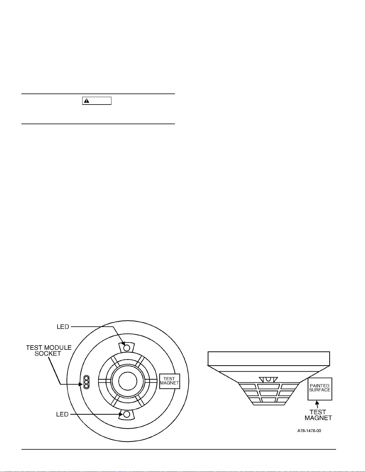
Figure 1. Bottom and side views showing position of test magnet:
LED
PAINTED
TEST MODULE
SOCKET
TEST
MAGNET
SURFACE
TEST
MAGNET
LED
D400-02-01 2 I56-277-08
Technical Manuals Online! - http://www.tech-man.com
A78-1213-00
Page 7
Testing
Before testing, notify the proper authorities that the smoke
detector system is undergoing maintenance and will temporarily be out of service. Disable the zone or system undergoing maintenance to prevent unwanted alarms.
Detectors must be tested after installation and periodic
maintenance. To test the 2451:
NOTE: Before testing the detector, check to ensure that the
LEDs are blinking. If they are not, the detector has
lost power (check the wiring) or it is defective (return for repair).
E. Direct Heat Test (2451TH only)
To test the bi-metallic thermal collector, aim a heat
source, such as a low powered heat gun or blow dryer,
across the detector. Hold the heat source about 12 inches
(30 cm) from the detector to avoid damaging the plastic.
When the temperature rises to greater than 135°F
(57°C), the detector should latch into the alarm. The bimetallic collector automatically resets after the test.
Notify the proper authorities that the detection system is
back on line.
A. Test Magnet (System Sensor model no. M02-04-00)
1. Place the magnet against the cover opposite the test
module slot to activate the test feature (see Figure 1).
2. The LEDs should latch on within 5 seconds indicating
alarm and annunciating the panel.
B. Calibrated Test Card (System Sensor no. R59-18-00)
1. Remove the detector cover by placing a small bladed
screwdriver in the side slot of the detector cover,
twisting it slightly until the cover can be turned counterclockwise for removal.
2. Insert the NO ALARM end of the test card fully into
the test slot (see Figure 2) then slide it counterclockwise until it stops.
3. Wait for at least 20 seconds. The detector should NOT
alarm.
4. Remove the test card by sliding it clockwise before removing, then insert the ALARM end.
5. The LEDs should latch on within 20 seconds indicating alarm and annunciating the panel.
6. Put the cover back by gently rotating it clockwise until it locks in place.
C. Test Module (System Sensor no. MOD400R)
The MOD400R is used with your DMM or voltmeter to
check the detector sensitivity as described in the
MOD400R’s manual.
Detectors that fail these tests should be cleaned as described under MAINTENANCE and retested. If the detectors still fail these tests they should be returned for repair.
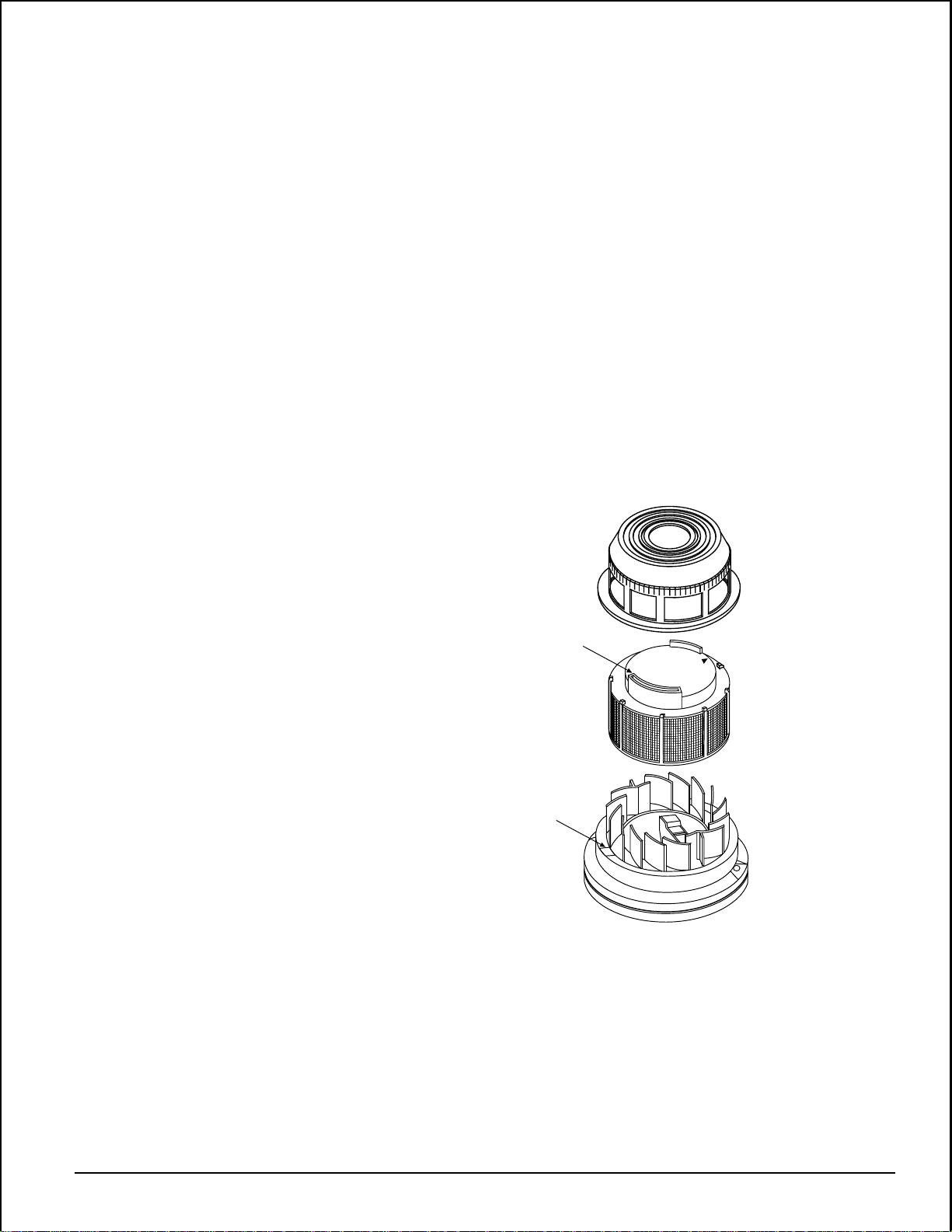
Figure 2:
REMOVABLE HEAD COVER
TEST SLOT
CLEANABLE SCREEN
P/N RS24 (W/O THERMAL)
HEAD COVER
REMOVAL SLOT
VANED CHAMBER
D. Aerosol Generator (Gemini 501)
Set the generator to represent 4% to 5%/Ft. obscuration
as described in the Gemini 501 Manual. Using the bowl
shaped applicator, apply aerosol until the unit alarms.
D400-02-01 3 I56-277-08
Technical Manuals Online! - http://www.tech-man.com
A78-1213-01
Page 8

Maintenance
It is recommended that the detector be removed from its
mounting base to facilitate easier cleaning. The detector is
cleaned as follows:
NOTE: Before removing the detector, notify the proper
authorities that the smoke detector system is undergoing maintenance and will temporarily be out
of service. Disable the zone or system undergoing
maintenance to prevent unwanted alarms.
1. Remove the detector cover by placing a small bladed
screwdriver in the side slot of the detector cover, twisting it slightly until the cover can be turned counterclockwise for removal.
2. Vacuum the screen carefully without removing it. If further cleaning is required continue with Step 3, otherwise
skip to Step 6.
The Limitations of Property Protection Smoke Detectors
This smoke detector is designed to activate and initiate emergency action, but will do so only when it is used in conjunction with an authorized
fire alarm system. This detector must be installed in accordance with
NFPA standard 72.
Smoke detectors will not work without power. AC or DC powered
smoke detectors will not work if the power supply is cut off.
Smoke detectors will not sense fires which start where smoke does not
reach the detectors. Smoldering fires typically do not generate a lot of
heat which is needed to drive the smoke up to the ceiling where the
smoke detector is usually located. For this reason, there may be large delays in detecting a smoldering fire with either an ionization type detector
or a photoelectric type detector. Either one of them may alarm only after
flaming has initiated which will generate the heat needed to drive the
smoke to the ceiling.
Smoke from fires in chimneys, in walls, on roofs or on the other side of a
closed door(s) may not reach the smoke detector and alarm it. A detector
cannot detect a fire developing on another level of a building quickly or at
all. For these reasons, detectors shall be located on every level and in
every bedroom within a building.
Smoke detectors have sensing limitations, too. Ionization detectors and
photoelectric detectors are required to pass fire tests of the flaming and
3. Remove the screen by pulling it straight out (see Figure
2). Vacuum the inside.
4. Clean the vaned chamber piece by vacuuming or blowing out dust and particles.
5. To replace the screen, orient it so that the arrow on top
aligns with the test module socket of the detector. Carefully push the screen onto the base making sure it fits
tightly to the chamber.
6. Replace the cover by gently rotating it clockwise until it
locks in place.
7. Reinstall the detector.
8. Notify the proper authorities that the system is back on
line.
WARNING
smoldering type. This is to ensure that both can detect a wide range of
types of fires. Ionization detectors offer a broad range of fire sensing capability but they are somewhat better at detecting fast flaming fires than
slow smoldering fires. Photoelectric detectors sense smoldering fires better
than flaming fires which have little, if any, visible smoke. Because fires develop in different ways and are often unpredictable in their growth, neither type of detector is always best, and a given detector may not always
provide early warning of a specific type of fire.
In general, detectors cannot be expected to provide warnings for fires resulting from inadequate fire protection practices, violent explosions, escaping gases which ignite, improper storage of flammable liquids like
cleaning solvents which ignite, other similar safety hazards, arson, smoking in bed, children playing with matches or lighters, etc. Smoke detectors
used in high air velocity conditions may have a delay in alarm due to dilution of smoke densities created by frequent and rapid air exchanges. Additionally, high air velocity environments may create increased dust
contamination, demanding more frequent maintenance.
Smoke detectors cannot last forever. Smoke detectors contain electronic
parts. Even though smoke detectors are made to last over 10 years, any
part can fail at any time. Therefore, smoke detectors shall be replaced after
being in service for 10 years. The smoke detector system that this detector
is used in must be tested regularly per NFPA 72. This smoke detector
should be cleaned regularly per NFPA 72 or at least once a year.
Three-Year Limited Warranty
System Sensor warrants its enclosed smoke detector to be free from defects in materials and workmanship under normal use and service for a
period of three years from date of manufacture. System Sensor makes no
other express warranty for this smoke detector. No agent, representative,
dealer, or employee of the Company has the authority to increase or alter
the obligations or limitations of this Warranty. The Company’s obligation
of this Warranty shall be limited to the repair or replacement of any part of
the smoke detector which is found to be defective in materials or workmanship under normal use and service during the three year period commencing with the date of manufacture. After phoning System Sensor’s toll
free number 800-SENSOR2 (736-7672) for a Return Authorization number,
send defective units postage prepaid to: System Sensor, Repair Depart-
D400-02-01 4 I56-277-08
Technical Manuals Online! - http://www.tech-man.com
ment, RA #__________, 3825 Ohio Avenue, St. Charles, IL 60174. Please
include a note describing the malfunction and suspected cause of failure.
The Company shall not be obligated to repair or replace units which are
found to be defective because of damage, unreasonable use, modifications, or alterations occurring after the date of manufacture. In no case
shall the Company be liable for any consequential or incidental damages
for breach of this or any other Warranty, expressed or implied whatsoever,
even if the loss or damage is caused by the Company’s negligence or fault.
Some states do not allow the exclusion or limitation of incidental or consequential damages, so the above limitation or exclusion may not apply to
you. This Warranty gives you specific legal rights, and you may also have
other rights which vary from state to state.
© System Sensor 1996
Page 9

INSTALLATION AND MAINTENANCE INSTRUCTIONS
4451HT and 4451HTA Plug-in
Fixed Intermediate Temperature
Thermal Detectors
Specifications
Diameter: 4.1 inches (104 mm)
Height: 2.1 inches (53 mm)
Weight: 5 ounces (150 g)
Installation Temperatures: 32° to 150°F (0° to 66°C)
Operating Humidity Range: 10% to 93% Relative Humidity
Latching Alarm: Reset by momentary power interruption
Sensitivity: 190°F (88°C)
Operating Voltage: 15-35 VDC
Standby Current: 100 µA
Before Installing
This detector must be installed in compliance with the control panel installation manual and meet the requirements of
the authority having jurisdiction. In addition, the National
Fire Protection Association has published codes, standards,
and recommended practices for the installation and use of
the above appliances (NFPA 72). For installation in Canada,
refer to CAN/ULC-S524 and CEC Part 1, Sec. 32. Therefore,
the installer must be familiar with these requirements, with
local codes, and any special requirements of the authority
having jurisdiction.
NOTICE: This manual should be left with the owner/user
of this equipment.
IMPORTANT: This detector must be tested and maintained
regularly following NFPA 72 requirements. The detector
should be cleaned at least once a year.
General Description
The 4451HT and 4451HTA detectors are fixed intermediate
temperature alarm thermal detectors utilizing a state-ofthe-art dual thermistor sensing circuit. These detectors are
designed to be used with compatible control panels only.
Two LEDs on each detector light to provide 360° visibility
of the detector indication. Remote LED annunciator capability is provided as standard, and the RA400Z remote LED
annunciator is available as an optional accessory.
Base Selection And Wiring Guide
Refer to the installation instructions for the plug-in detector
bases for base selection and wiring instructions. System
Sensor has available a variety of detector bases for these
heat detectors, including 2-wire applications with and
without relays and/or current limiting resistors for use with
control panels that require one. These detectors are only to
be used with 400 and 400B series bases.
A Division of Pittway
3825 Ohio Avenue, St. Charles, Illinois 60174
1-800-SENSOR2, FAX: 630-377-6495
D400-54-00 1 I56-690-04
Technical Manuals Online! - http://www.tech-man.com
Install the System Sensor plug-in base to be used with the
detector following the instructions in the base manual.
Page 10
Installation
NOTE: All wiring must conform to applicable installation
codes and regulations.
NOTE: Verify that all detector bases are installed, that the
initiating-device circuits have been tested, and that
the wiring is correct. (Refer to detector base
manual for testing procedure.)
Tamper-Resistance Feature
The detector bases include a feature that, when activated,
prevents removal of the detector without the use of a tool.
Refer to the installation instruction manual of the detector
base to make use of this capability.
2. After all detectors have been installed, apply power to
the control unit.
CAUTION
Disconnect the power from initiating-device circuits before
installing detectors.
1. Install Detectors:
a. Insert the detector into the detector base.
b. Turn the detector clockwise until the detector drops
into place.
c. Continue turning detector clockwise to lock it in place.
Figure 1. Test magnet position:
3. Test the detector using the magnet as described under
TESTING.
4. Reset the detector at the system control panel.
5. Notify the proper authorities the system is in operation.
D400-54-00 2 I56-690-04
Technical Manuals Online! - http://www.tech-man.com
Page 11

Testing
Before testing, notify the proper authorities that the heat
detector system is undergoing maintenance, and therefore
the system will temporarily be out of service. Disable the
zone or system undergoing maintenance to prevent unwanted alarms.
Detectors must be tested after installation and periodic
maintenance. Test the detector as follows:
Maintenance
The 4451HT and 4451HTA detectors have been designed to
be as maintenance-free as possible. Normal air-borne dust,
however, can accumulate on the detector’s sensing elements and cause them to become less sensitive. All detectors should be tested and cleaned at least once a year, and
those in dustier areas should be tested and cleaned more
often. Detectors must also be cleaned and tested immediately after a fire.
A. Test Magnet (System Sensor Model M02-04)
1. Position the magnet against the cover opposite the
test module socket. (See Figure 1.)
2. The LEDs on the detector should light within 10 seconds. If the LEDs fail to light, check the power to the
detector and the wiring in the detector base.
3. Reset the detector at the system control panel.
B. Test Module (System Sensor Model MOD400R)
The MOD400R is used with a DMM or voltmeter to
check the detector sensitivity as described in the
module’s manual.
C. Direct Heat Method (Heat Gun)
1. From the side of the detector, direct the heat toward
the sensor. Hold the heat source about 15 cm away to
prevent damage to the cover during testing.
Before cleaning, notify the proper authorities that the system is undergoing maintenance and therefore the system
will temporarily be out of service. Disable the loop or system undergoing maintenance to prevent unwanted alarms.
1. Remove detector from mounting base.
2. Use a vacuum cleaner to remove dust from the sensing
chamber.
3. Reinstall the detector.
4. Test the detector as described under TESTING.
CAUTION
Avoid exposing the detector cover to the heat source for
more than 15 seconds. Extended periods of extreme heat
can melt the plastic and damage the cover.
NOTE: If a detector goes into alarm, it will reset only if the
detector has cooled and if its power is momentarily
interrupted. Check the control panel being used to
determine whether the RESET switch (or some
other auxiliary device or control) momentarily cuts
off power to the detector loop.
Detectors that fail these tests should be cleaned as described under MAINTENANCE and retested. If the detectors still fail these tests they should be returned for repair.
D400-54-00 3 I56-690-04
Technical Manuals Online! - http://www.tech-man.com
Page 12

The Limitations of Property Protection Heat Detectors
This heat detector is designed to activate and initiate emergency action,
but will do so only when it is used in conjunction with an authorized fire
alarm system. This detector must be installed in accordance with NFPA
Standard 72.
Heat detectors will not work without power. AC or DC-powered smoke
detectors will not work if the power supply is cut off for any reason.
Heat detectors are designed to protect property, not life. They do not
provide early warning of fire and cannot detect smoke, gas, combustion
particles, or flame. They alarm when temperatures at the heat detector
reach 57°C (135°F). Given the rapid growth of certain types of fires, heat
detectors cannot be expected to provide adequate warning of fires
resulting from smoking in bed, inadequate fire protection practices,
violent explosions, escaping gas, improper storage of flammable liquids
like cleaning solvents, other safety hazards, or arson.
Three-Year Limited Warranty
System Sensor warrants its enclosed heat detector to be free from defects
in materials and workmanship under normal use and service for a period
of three years from date of manufacture. System Sensor makes no other
express warranty for this heat detector. No agent, representative, dealer, or
employee of the Company has the authority to increase or alter the obligations or limitations of this Warranty. The Company’s obligation of this
Warranty shall be limited to the repair or replacement of any part of the
heat detector which is found to be defective in materials or workmanship
under normal use and service during the three year period commencing
with the date of manufacture. After phoning System Sensor’s toll free
number 800-SENSOR2 (736-7672) for a Return Authorization number,
send defective units postage prepaid to: System Sensor, Repair Depart-
WARNING
Heat detectors do not always detect fires because the fire may be a
slow-smoldering, low-heat type (producing smoke), or because they
may not be near where the fire occurs, or because the heat of the fire
may bypass them. Heat detectors will not detect smoke, gas, flames, or
combustion particles.
Heat detectors are components in professionally-installed fire alarm
systems. They will not function if they have been improperly wired
into the fire alarm system or if power to them is cut off for any reason.
Heat detectors cannot last forever. They should be tested and maintained
following the instructions in this manual. To be safe, they should be
replaced 15 years after installation.
Refer to NFPA 72 for application.
ment, RA #__________, 3825 Ohio Avenue, St. Charles, IL 60174. Please
include a note describing the malfunction and suspected cause of failure.
The Company shall not be obligated to repair or replace units which are
found to be defective because of damage, unreasonable use, modifications, or alterations occurring after the date of manufacture. In no case
shall the Company be liable for any consequential or incidental damages
for breach of this or any other Warranty, expressed or implied whatsoever,
even if the loss or damage is caused by the Company’s negligence or fault.
Some states do not allow the exclusion or limitation of incidental or consequential damages, so the above limitation or exclusion may not apply to
you. This Warranty gives you specific legal rights, and you may also have
other rights which vary from state to state.
D400-54-00 4 I56-690-04
Technical Manuals Online! - http://www.tech-man.com
© System Sensor 1996
Page 13

INSTALLATION AND MAINTENANCE INSTRUCTIONS
5451 Plug-in Rate-of-Rise
Thermal Detector with
Fixed Temperature Alarm
Specifications
Diameter: 4.1 inches (104 mm)
Height: 2.1 inches (53 mm)
Weight: 5 ounces (150 g)
Installation Temperatures: 32° to 100°F (0° to 38°C)
Operating Humidity Range: 10% to 93% Relative Humidity
Latching Alarm: Reset by momentary power interruption
Sensitivity 135°F (57°C) Fixed or 15°F/min rate-of-rise
Operating Voltage: 15-35 VDC
Standby Current: 100 µA
Before Installing
This detector must be installed in compliance with the
control panel installation manual and meet the requirements of the authority having jurisdiction. In addition, the
National Fire Protection Association has published codes,
standards, and recommended practices for the installation
and use of detectors, NFPA 72.
(For installation in Canada, refer to CAN/ULC-S524, Standard for the Installation of Fire Alarm Systems and CEC
Part 1, Sec. 32.)
General Description
Model 5451 is a rate-of-rise with fixed temperature alarm
thermal detector utilizing a state-of-the-art dual thermistor
sensing circuit. These detectors are designed to provide
open area protection with 50-foot spacing capability, and
are to be used with compatible control panels only.
Two LEDs on each detector light to provide 360° visibility
of the detector indication. Remote LED annunciator capability is provided as standard, and the RA400Z remote LED
annunciator is available as an optional accessory.
A Division of Pittway
3825 Ohio Avenue, St. Charles, Illinois 60174
1-800-SENSOR2, FAX: 630-377-6495
Therefore, the installer must be familiar with these requirements, with local codes, and any special requirements of the authority having jurisdiction.
NOTICE: This manual should be left with the owner/user
of this equipment.
IMPORTANT: This detector must be tested and maintained regularly following NFPA 72 requirements. The detector should be cleaned at least once a year.
Base Selection and Wiring Guide
Refer to the installation instructions for the plug-in detector
bases for base selection and wiring instructions. System
Sensor has available a variety of detector bases for these
heat detectors, including 2-wire applications with and
without relays and/or current limiting resistors for use with
control panels that require one. This detector is only to be
used with 400 and 400B series bases.
Install the System Sensor plug-in base to be used with the
detector following the instructions in the base manual.
D400-29-00 1 I56-580-03
Technical Manuals Online! - http://www.tech-man.com
Page 14
Installation
NOTE: All wiring must conform to applicable installation
codes and regulations.
NOTE: Verify that all detector bases are installed, that the
initiating-device circuits have been tested, and that
the wiring is correct. (Refer to detector base
manual for testing procedure.)
WARNING
Disconnect the power from initiating-device circuits before
installing detectors.
Tamper Resistance
The detector bases include a feature that, when activated,
prevents removal of the detector without the use of a tool.
Refer to the installation instruction manual of the detector
base to make use of this capability.
Testing
Before testing, notify the proper authorities that the heat
detector system is undergoing maintenance, and therefore
the system will temporarily be out of service. Disable the
zone or system undergoing maintenance to prevent unwanted alarms.
1. Install Detectors:
Detectors must be tested after installation and periodic
maintenance. The 5451 may be tested as follows:
a. Insert the detector into the detector base.
b. Turn the detector clockwise until the detector drops
A. Test Magnet (System Sensor Model No. M02-04)
into place.
c. Continue turning detector clockwise to lock it in
place.
2. After all detectors have been installed, apply power to
the control unit.
1. Position the magnet against the cover opposite the
test module socket. (See Figure 1.)
2. The LEDs on the detector should light within 10 seconds. If the LEDs fail to light, check the power to the
detector and the wiring in the detector base.
3. Test the detector using the magnet as described under
TESTING.
3. Reset the detector at the system control panel.
4. Reset the detector at the system control panel.
5. Notify the proper authorities that the system is in operation.
Figure 1. Bottom and Side Views Showing Position of Test Magnet:
D400-29-00 2 I56-580-03
Technical Manuals Online! - http://www.tech-man.com
Page 15

B. Test Module (System Sensor Model No. MOD400 or
MOD400R)
The MOD400 or MOD400R is used with a DMM or volt
meter to check the detector sensitivity as described in
the module’s manual.
C. Direct Heat Method (Hair dryer of 1000 - 1500 watts)
Maintenance
The 5451 detector has been designed to be as maintenancefree as possible. Normal air-borne dust, however, can accumulate on the detector’s sensing elements and cause them
to become less sensitive. All detectors should be tested and
cleaned at least once a year, and those in dustier areas
should be tested and cleaned more often. Detectors must
also be cleaned and tested immediately after a fire.
From the side of the detector, direct the heat toward the
sensor. Hold the heat source about 15 cm away to prevent damage to the cover during testing.
NOTE: If a detector goes into alarm, it will reset only if the
detector has cooled and if its power is momentarily
interrupted. Check the control panel being used to
determine whether the RESET switch (or some
other auxiliary device or control) momentarily cuts
off power to the detector loop.
Detectors that fail these tests should be cleaned as described under MAINTENANCE and retested. If the detectors still fail these tests they should be returned for repair.
Before cleaning, notify the proper authorities that the system is undergoing maintenance and therefore the system
will temporarily be out of service. Disable the loop or system undergoing maintenance to prevent unwanted alarms.
1. Remove detector from mounting base.
2. Use a vacuum cleaner to remove dust from the sensing
chamber.
3. Reinstall the detector.
4. Test detector as described under TESTING.
D400-29-00 3 I56-580-03
Technical Manuals Online! - http://www.tech-man.com
Page 16

WARNING
The Limitations of Property Protection Heat Detectors
This heat detector is designed to activate and initiate emergency action,
but will do so only when it is used in conjunction with an authorized fire
alarm system. This detector must be installed in accordance with NFPA
Standard 72.
Heat detectors will not work without power. AC or DC-powered smoke
detectors will not work if the power supply is cut off for any reason.
Heat detectors are designed to protect property, not life. They do not
provide early warning of fire and cannot detect smoke, gas, combustion
particles, or flame. They alarm when temperatures at the heat detector
reach 57°C (135°F). Given the rapid growth of certain types of fires, heat
detectors cannot be expected to provide adequate warning of fires
resulting from smoking in bed, inadequate fire protection practices,
violent explosions, escaping gas, improper storage of flammable liquids
like cleaning solvents, other safety hazards, or arson.
Three-Year Limited Warranty
System Sensor warrants its enclosed heat detector to be free from defects
in materials and workmanship under normal use and service for a period
of three years from date of manufacture. System Sensor makes no other
express warranty for this heat detector. No agent, representative, dealer, or
employee of the Company has the authority to increase or alter the obligations or limitations of this Warranty. The Company’s obligation of this
Warranty shall be limited to the repair or replacement of any part of the
heat detector which is found to be defective in materials or workmanship
under normal use and service during the three year period commencing
with the date of manufacture. After phoning System Sensor’s toll free
number 800-SENSOR2 (736-7672) for a Return Authorization number,
send defective units postage prepaid to: System Sensor, Repair Depart-
Heat detectors do not always detect fires because the fire may be a
slow-smoldering, low-heat type (producing smoke), or because they
may not be near where the fire occurs, or because the heat of the fire
may bypass them. Heat detectors will not detect smoke, gas, flames, or
combustion particles.
Heat detectors are components in professionally installed fire alarm
systems. They will not function if they have been improperly wired
into the fire alarm system or if power to them is cut off for any reason.
Heat detectors cannot last forever. They should be tested and maintained
following the instructions in this manual. To be safe, they should be
replaced after they have been installed for 15 years.
Refer to NFPA 72 for application.
ment, RA #__________, 3825 Ohio Avenue, St. Charles, IL 60174. Please
include a note describing the malfunction and suspected cause of failure.
The Company shall not be obligated to repair or replace units which are
found to be defective because of damage, unreasonable use, modifications, or alterations occurring after the date of manufacture. In no case
shall the Company be liable for any consequential or incidental damages
for breach of this or any other Warranty, expressed or implied whatsoever,
even if the loss or damage is caused by the Company’s negligence or fault.
Some states do not allow the exclusion or limitation of incidental or consequential damages, so the above limitation or exclusion may not apply to
you. This Warranty gives you specific legal rights, and you may also have
other rights which vary from state to state.
D400-29-00 4 I56-580-03
Technical Manuals Online! - http://www.tech-man.com
© System Sensor 1996
Page 17

INSTALLATION AND MAINTENANCE INSTRUCTIONS
B401B Plug-in Detector Base
For use with the following smoke detectors:
1451, 2451, and 2451TH
Specifications
Base Diameter: 6.2 inches (15.7 cm)
Base Height: 1.1 inches (2.8 cm)
Weight: 0.3 lb. (130 g)
Mounting: 4-inch square box with or without plaster ring. Min. Depth–1.5 inches
4-inch octagon box. Min. Depth–1.5 inches
3-1/2 inch octagon box. Min. Depth–1.5 inches
Operating Temperature Range: 0° to +49°C (32° to 120°F)
Operating Humidity Range: 10% to 93% Relative Humidity, noncondensing
Electrical Ratings — includes base and detector
System Voltage: 12/24 VDC
Maximum Ripple Voltage: 4 Volts peak to peak
Start-up Capacitance: 0.02 µF Maximum
Standby Ratings: 8.5 VDC Minimum; 35 VDC Maximum
120 µA Maximum
Alarm Ratings: 4.2 VDC Minimum at 10 mA; 6.6 VDC Maximum at 100 mA
(Alarm current must be limited to 100 mA by the control panel. If used, the RA400
remote lamp operates within specified detector alarm currents.)
Reset Voltage: 2.5 VDC Minimum
Reset Time: 0.3 Seconds Maximum
Start-up Time: 34.0 Seconds Maximum
3825 Ohio Avenue, St. Charles, Illinois 60174
1-800-SENSOR2, FAX: 630-377-6495
A Division of Pittway
Before Installing
Please thoroughly read the System Sensor manual I56-407,
Guide for Proper Use of System Smoke Detectors, which
provides detailed information on detector spacing, placement, zoning, wiring, and special applications. Copies of
this manual are available at no charge from System Sensor.
(For installations in Canada, refer to CAN4-S524, Standard
for the Installation of Fire Alarm Systems, and CEC Part 1,
Sec. 32.)
NOTICE: This manual should be left with the owner/user
of this equipment.
IMPORTANT: The detector used with this base must be
tested and maintained regularly following NFPA 72 requirements. The detector used with this base should be cleaned
at least once a year.
General Description
The B401B plug-in detector base is used with System Sensor model 2451 and 2451TH photoelectronic detector heads
and model 1451A ionization detector heads. The capability
of plugging these detectors into a variety of special bases
makes them more versatile than equivalent direct-wired
models. Refer to the System Sensor catalog for other available plug-in detector bases.
This base is intended for use in 2-wire systems, with screw
terminals provided for power, ground, and remote annunciator connections.
D450-01-01 1 I56-298-08
Technical Manuals Online! - http://www.tech-man.com
Page 18

Mounting
This detector base mounts directly to 3-1/2-inch and 4-inch
octagon boxes, and 4-inch square boxes (with or without
plaster rings). To mount, remove the decorative ring by
turning it in either direction to unhook the snaps, then
separate the ring from the base.
Install the base to the box using the screws supplied with
the junction box and the appropriate mounting slots in the
base (see Figure 1). Place decorative ring onto base, then
turn in either direction until the ring snaps in place.
Installation Guidelines
All wiring must be installed in compliance with the National Electrical Code and the local codes having jurisdiction. Proper wire gauges should be used. The conductors
used to connect smoke detectors to control panels and accessory devices should be color-coded to reduce the likelihood of wiring errors. Improper connections can prevent a
system from responding properly in the event of a fire.
For signal wiring (the wiring between interconnected detectors), it is recommended that the wire be no smaller
than 18 gauge (1.0 square mm). Wire sizes up to 12 gauge
wire (2.5 square mm) may be used with the base. For best
system performance, the power (+) and (–) loop wires
should be twisted pair and installed in separate grounded
conduit to protect the loop from extraneous electrical interference.
Smoke detectors and alarm system control panels have
specifications for allowable loop resistance. Consult the
control panel manufacturer’s specifications for the total
Figure 1. Mounting base to box:
SNAP ON
DECORATIVE
RING
SCREWS (NOT
SHORTING
SPRING
SUPPLIED)
DETECTOR
BASE
BOX (NOT
SUPPLIED)
A78-1175-01
loop resistance allowed for the particular model control
panel being used before wiring the detector loops.
Locate installations where the normal ambient temperatures do not exceed 100° F.
Figure 2. Typical wiring diagram for 2-wire detector systems:
2
1
REMOTE
ANNUNCIATOR
2-WIRE CONTROL PANEL
D450-01-01 2 I56-298-08
3
4
REMOTE
ANNUNCIATOR
CLASS A OPTIONAL WIRING
2
1
3
4
E
O
L
Technical Manuals Online! - http://www.tech-man.com
A78-1175-04
Page 19

Wiring Instructions
Tamper-resistance Feature
CAUTION
For system supervision — For terminals 2, 3, and 4 do not
use looped wire under terminals. Break wire run to provide
system supervision of connections.
Wire connections are made by simply stripping insulation
from the end of the wire, sliding the bare end of the wire
under the clamping plate, and tightening the clamping
plate screw. Use the strip gauge molded into the base for
ease of wiring to terminals 1 through 4.
System Sensor smoke detectors and mounting bases are
marked with a compatibility identifier located as the last
digit of a five digit code stamped on the back of the product. Connect detectors/mounting bases only to compatible
control units as indicated in System Sensor’s compatibility
chart which contains a current list of UL listed control units
and detector head/base combinations. A copy of this list is
available from System Sensor upon request.
The zone wiring of the detector base should be checked
before the detector heads are installed in them. To make
this possible, this base contains a special spring-type shorting jumper. After a detector base is properly wired and
mounted on an electrical box, make sure that the jumper
spring is in contact with the base of Terminal 3. This temporary connection shorts the negative-in and negative-out
leads and permits the wiring of the loop to be checked for
continuity.
CAUTION
Do not use the tamper-resistance feature if the XR2 removal
tool is to be used.
The tamper-resistant tab, in the detector mounting bracket,
can make the detector tamper-resistant by making it necessary to use a small screwdriver or similar tool to detach the
detector from the bracket.
To make the detector tamper-resistant, use needle-nose pliers to break the smaller tab at the scribed line on the
tamper- resistance tab. Figure 3A shows the location of this
tab on the detector mounting bracket. To remove a detector
from the bracket after it has been made tamper resistant,
use a small screwdriver or other similar tool, to depress the
tamper-resistance tab in the slot on the mounting bracket,
and rotate the detector counterclockwise (see Figure 3B).
NOTE: The decorative ring must be removed before the
smoke detector can be detached from the base after the tamper-resistant capability is enabled.
The tamper-resistance feature can be defeated by breaking
and removing the plastic lever from the base. However, this
prevents ever using the feature again.
Once all the detector bases have been wired and mounted,
and the loop wiring has been checked, the detector heads
may be installed in the bases. The shorting spring in the
base will disengage automatically when the detector head
is removed from the base. DO NOT remove the shorting
spring since it reengages as the detector head is turned into
the base, completing the circuit.
Figure 3A. Activating the tamper-resistance feature:
BREAK TAB AT
PLASTIC LEVER
D450-01-01 3 I56-298-08
DOTTED LINE BY
TWISTING TOWARD
CENTER OF BASE.
Technical Manuals Online! - http://www.tech-man.com
Figure 3B. Removing detector head from the base:
USE SMALL-BLADED
SCREWDRIVER TO
PUSH PLASTIC LEVER
IN DIRECTION OF
ARROW.
A78-1175-03
Page 20

The Limitations of Property Protection Smoke Detectors
The smoke detector used with this base is designed to activate and initiate emergency action, but will do so only when it is used in conjunction
with an authorized fire alarm system. This detector must be installed in
accordance with NFPA standard 72.
Smoke detectors will not work without power. AC or DC powered
smoke detectors will not work if the power supply is cut off.
Smoke detectors will not sense fires which start where smoke does not
reach the detectors. Smoldering fires typically do not generate a lot of
heat which is needed to drive the smoke up to the ceiling where the
smoke detector is usually located. For this reason, there may be large delays in detecting a smoldering fire with either an ionization type detector
or a photoelectric type detector. Either one of them may alarm only after
flaming has initiated which will generate the heat needed to drive the
smoke to the ceiling.
Smoke from fires in chimneys, in walls, on roofs or on the other side of a
closed door(s) may not reach the smoke detector and alarm it. A detector
cannot detect a fire developing on another level of a building quickly or at
all. For these reasons, detectors shall be located on every level and in
every bedroom within a building.
Smoke detectors have sensing limitations, too. Ionization detectors and
photoelectric detectors are required to pass fire tests of the flaming and
WARNING
smoldering type. This is to ensure that both can detect a wide range of
types of fires. Ionization detectors offer a broad range of fire sensing capability but they are somewhat better at detecting fast flaming fires than
slow smoldering fires. Photoelectric detectors sense smoldering fires better
than flaming fires which have little, if any, visible smoke. Because fires develop in different ways and are often unpredictable in their growth, neither type of detector is always best, and a given detector may not always
provide early warning of a specific type of fire.
In general, detectors cannot be expected to provide warnings for fires resulting from inadequate fire protection practices, violent explosions, escaping gases which ignite, improper storage of flammable liquids like
cleaning solvents which ignite, other similar safety hazards, arson, smoking in bed, children playing with matches or lighters, etc. Smoke detectors
used in high air velocity conditions may have a delay in alarm due to dilution of smoke densities created by frequent and rapid air exchanges. Additionally, high air velocity environments may create increased dust
contamination, demanding more frequent maintenance.
Smoke detectors cannot last forever. Smoke detectors contain electronic
parts. Even though smoke detectors are made to last over 10 years, any
part can fail at any time. Therefore, smoke detectors shall be replaced after
being in service for 10 years. The smoke detector system that this detector
is used in must be tested regularly per NFPA 72. This smoke detector
should be cleaned regularly per NFPA 72 or at least once a year.
Three-Year Limited Warranty
System Sensor warrants its enclosed smoke detector base to be free from
defects in materials and workmanship under normal use and service for a
period of three years from date of manufacture. System Sensor makes no
other express warranty for this smoke detector base. No agent, representative, dealer, or employee of the Company has the authority to increase or
alter the obligations or limitations of this Warranty. The Company’s obligation of this Warranty shall be limited to the repair or replacement of any
part of the smoke detector base which is found to be defective in materials
or workmanship under normal use and service during the three year period commencing with the date of manufacture. After phoning System
Sensor’s toll free number 800-SENSOR2 (736-7672) for a Return Authorization number, send defective units postage prepaid to: System Sensor,
D450-01-01 4 I56-298-08
Technical Manuals Online! - http://www.tech-man.com
Repair Department, RA #__________, 3825 Ohio Avenue, St. Charles, IL
60174. Please include a note describing the malfunction and suspected
cause of failure. The Company shall not be obligated to repair or replace
units which are found to be defective because of damage, unreasonable
use, modifications, or alterations occurring after the date of manufacture.
In no case shall the Company be liable for any consequential or incidental
damages for breach of this or any other Warranty, expressed or implied
whatsoever, even if the loss or damage is caused by the Company’s negligence or fault. Some states do not allow the exclusion or limitation of incidental or consequential damages, so the above limitation or exclusion may
not apply to you. This Warranty gives you specific legal rights, and you
may also have other rights which vary from state to state.
© System Sensor 1996
Page 21

INSTALLATION AND MAINTENANCE INSTRUCTIONS
B401BR Plug-in Detector Base
For use with the following detectors: 1451, 2451, and 2451TH
Specifications
Base Diameter: 6.2 inches (157 mm) typical
Base Height: 1.1 inches (29 mm) typical
Weight: 0.3 lb. (130 g) typical
Mounting: 4 inch square box with or without plaster ring. Min. Depth: 1.5 inches
4 inch octagon box. Min. Depth: 1.5 inches
3-1/2 inch octagon box. Min. Depth: 1.5 inches
Operating Temperature Range: –10° to 60°C (14° to 140°F)
Note: Do not install where normal ambient temperature extends beyond 0° to 49°
(32° to 120°F)
Operating Humidity Range: 10% to 93% Relative Humidity
Electrical Ratings — includes base and detector
System Voltage: 24 VDC
Maximum Ripple Voltage: 4 Volts peak to peak
Start-up Capacitance: 0.02 µF Maximum
Standby Ratings: 17 VDC Minimum
32 VDC Maximum
120 µA Maximum
Alarm Ratings: 10 mA Minimum at 10.5 VDC
62 mA Maximum at 32 VDC
The optional RA400Z Remote Annunciator operates within the specified detector
alarm currents.
Reset Voltage: 2.50 VDC Minimum
Reset Time: 0.3 Sec Maximum
Start-up Time: 34.0 Sec Maximum
3825 Ohio Avenue, St. Charles, Illinois 60174
1-800-SENSOR2, FAX: 630-377-6495
A Division of Pittway
Before Installing
Please thoroughly read the System Sensor manual I56-407,
Guide for Proper Use of System Smoke Detectors, which
provides detailed information on detector spacing,
placement, zoning, wiring, and special applications. Copies
of this manual are available at no charge from System
Sensor. (For installations in Canada, refer to CAN4-S524,
Standard for the Installation of Fire Alarm Systems, and
CEC Part 1, Sec. 32.)
NOTICE: This manual should be left with the owner/user
of this equipment.
IMPORTANT: The detector used with this base must be
tested and maintained regularly following NFPA 72 requirements. The detector used with this base should be cleaned
at least once a year.
D450-02-00 1 I56-352-05
Technical Manuals Online! - http://www.tech-man.com
General Description
The plug-in detector base B401BR is used with System Sensor 400 Series photoelectronic, ionization, and heat detector heads. The ability to accept a variety of detector heads
makes this base more versatile than equivalent direct-wired
models. Refer to the System Sensor catalog for other available plug-in detector bases.
This B401BR base is intended for use in 2-wire systems,
with screw terminals provided for power, ground, and remote annunciator connections. The B401BR base also contains a resistor to provide current limiting in the alarm
state.
Page 22

Mounting
This detector base mounts directly to 3-1/2 inch and 4 inch
octagon boxes, and 4 inch square boxes (with or without
plaster rings). To mount, remove decorative ring by turning
it in either direction to unhook the snaps, then separate the
ring from the base.
Figure 1. Mounting detector to box:
Install the base to the box using the screws supplied with
the junction box and the appropriate mounting slots in the
base. Place decorative ring onto base, then turn in either direction until the ring snaps in place (see Figure 1).
Installation Guidelines
All wiring must be installed in compliance with the National Electrical Code and the local codes having jurisdiction. Proper wire gauges should be used. The conductors
used to connect smoke detectors to control panels and accessory devices should be color-coded to prevent wiring
mistakes. Improper connections can prevent a system from
responding properly in the event of a fire.
For signal wiring (the wiring between interconnected detectors), it is recommended that the wire be no smaller
than 18 gauge (1.0 square mm). Wire sizes up to 12 gauge
wire (2.5 square mm) may be used with the base. For best
system performance, the power (+ and –) loop wires
should be twisted pair and installed in separate grounded
conduit to protect the loop from electrical interference.
Smoke detectors and alarm system control panels have
specifications for allowable loop resistance. Consult the
control panel manufacturer’s specifications for the total
loop resistance allowed for the particular model control
panel being used before wiring the detector loops.
SNAP ON
DECORATIVE
RING
SCREWS (NOT
SUPPLIED)
SHORTING
SPRING
DETECTOR
BASE
BOX (NOT
SUPPLIED)
A78-1175-01
CAUTION
For system supervision — For terminals 2, 3, and 5 do not
use looped wire under terminals. Break wire run to provide
system supervision of connections.
available from System Sensor upon request.
The zone wiring of the detector base should be checked
before the detector heads are installed in them. To make
this possible, this base contains a special spring-type short-
ing jumper. After a detector base is properly wired and
Wire connections are made by simply stripping insulation
from the end of the wire, sliding the bare end of the wire
under the clamping plate, and tightening the clamping
plate screw. Use the strip gauge molded into the base for
ease of wiring to terminals.
System Sensor smoke detectors and mounting bases are
marked with a compatibility identifier located as the last
digit of a five digit code stamped on the back of the product. Connect detectors/mounting bases only to compatible
control units as indicated in System Sensor’s compatibility
mounted on an electrical box, make sure that the jumper
spring is in contact with the base of Terminal 3. This tem-
porary connection shorts the negative-in and negative-out
leads and permits the wiring of the loop to be checked for
continuity.
Once all the detector bases have been wired and mounted,
and the loop wiring has been checked, the detector heads
may be installed in the bases. The shorting spring in the
base will disengage when the detector head is turned into
place.
chart which contains a current list of UL listed control units
and detector head/base combinations. A copy of this list is
D450-02-00 2 I56-352-05
Technical Manuals Online! - http://www.tech-man.com
Page 23

Figure 2. Typical wiring diagram for 2-wire detector systems:
–
NOTE: For system supervision - Do not loop wire under
terminals 2, 3, and 5. Break wire run to ensure
system supervision of connections.
–
+
2
1
3
5
4
REMOTE
ANNUNCIATOR
2-WIRE CONTROL PANEL
+
+
–
Tamper-resist Feature
CAUTION
Do not use the tamper resist feature if the XR5 removal tool
is to be used.
This detector base also includes an optional tamper resist
feature that, when activated, prevents removal of the detector without the use of a tool.
2
–
+
1
3
5
4
E
O
L
REMOTE
ANNUNCIATOR
OPTIONAL FAULT TOLERANT WIRING
A78-1175-10
Note: Head removal after the tamper resist feature has
been activated first requires removal of the decorative ring.
The tamper resist feature can be defeated by breaking and
removing the plastic lever from the base. However, this permanently defeats the tamper resist feature.
To activate this feature, break the tab from the detector
base, as shown in Figure 3A, and install the detector. To remove the detector from the base once the tamper resist feature has been activated, insert a small-bladed screwdriver
into the slot in the side of the base and press the plastic lever away from the detector head (see Figure 3B). This allows the detector to be rotated counterclockwise and
removed.
BREAK TAB AT
PLASTIC LEVER
DOTTED LINE BY
TWISTING TOWARD
CENTER OF BASE.
Figure 3B. Removing detector head from base:Figure 3A. Activating tamperproof feature:
USE SMALL-BLADED
SCREWDRIVER TO
PUSH PLASTIC LEVER
IN DIRECTION OF
ARROW.
A78-1175-03
D450-02-00 3 I56-352-05
Technical Manuals Online! - http://www.tech-man.com
Page 24

WARNING
The Limitations of Property Protection Smoke Detectors
The smoke detector used with this base is designed to activate and initiate emergency action, but will do so only when it is used in conjunction
with an authorized fire alarm system. This detector must be installed in
accordance with NFPA standard 72.
Smoke detectors will not work without power. AC or DC powered
smoke detectors will not work if the power supply is cut off.
Smoke detectors will not sense fires which start where smoke does not
reach the detectors. Smoldering fires typically do not generate a lot of
heat which is needed to drive the smoke up to the ceiling where the
smoke detector is usually located. For this reason, there may be large delays in detecting a smoldering fire with either an ionization type detector
or a photoelectric type detector. Either one of them may alarm only after
flaming has initiated which will generate the heat needed to drive the
smoke to the ceiling.
Smoke from fires in chimneys, in walls, on roofs or on the other side of a
closed door(s) may not reach the smoke detector and alarm it. A detector
cannot detect a fire developing on another level of a building quickly or at
all. For these reasons, detectors shall be located on every level and in
every bedroom within a building.
Smoke detectors have sensing limitations, too. Ionization detectors and
photoelectric detectors are required to pass fire tests of the flaming and
smoldering type. This is to ensure that both can detect a wide range of
types of fires. Ionization detectors offer a broad range of fire sensing capa-
bility but they are somewhat better at detecting fast flaming fires than
slow smoldering fires. Photoelectric detectors sense smoldering fires better
than flaming fires which have little, if any, visible smoke. Because fires de-
velop in different ways and are often unpredictable in their growth, nei-
ther type of detector is always best, and a given detector may not always
provide early warning of a specific type of fire.
In general, detectors cannot be expected to provide warnings for fires re-
sulting from inadequate fire protection practices, violent explosions, es-
caping gases which ignite, improper storage of flammable liquids like
cleaning solvents which ignite, other similar safety hazards, arson, smok-
ing in bed, children playing with matches or lighters, etc. Smoke detectors
used in high air velocity conditions may have a delay in alarm due to dilu-
tion of smoke densities created by frequent and rapid air exchanges. Addi-
tionally, high air velocity environments may create increased dust
contamination, demanding more frequent maintenance.
Smoke detectors cannot last forever. Smoke detectors contain electronic
parts. Even though smoke detectors are made to last over 10 years, any
part can fail at any time. Therefore, smoke detectors shall be replaced after
being in service for 10 years. The smoke detector system that this detector
is used in must be tested regularly per NFPA 72. This smoke detector
should be cleaned regularly per NFPA 72 or at least once a year.
Three-Year Limited Warranty
System Sensor warrants its enclosed smoke detector base to be free from
defects in materials and workmanship under normal use and service for a
period of three years from date of manufacture. System Sensor makes no
other express warranty for this smoke detector base. No agent, representative, dealer, or employee of the Company has the authority to increase or
alter the obligations or limitations of this Warranty. The Company’s obligation of this Warranty shall be limited to the repair or replacement of any
part of the smoke detector base which is found to be defective in materials
or workmanship under normal use and service during the three year period commencing with the date of manufacture. After phoning System
Sensor’s toll free number 800-SENSOR2 (736-7672) for a Return Authorization number, send defective units postage prepaid to: System Sensor,
D450-02-00 4 I56-352-05
Technical Manuals Online! - http://www.tech-man.com
Repair Department, RA #__________, 3825 Ohio Avenue, St. Charles, IL
60174. Please include a note describing the malfunction and suspected
cause of failure. The Company shall not be obligated to repair or replace
units which are found to be defective because of damage, unreasonable
use, modifications, or alterations occurring after the date of manufacture.
In no case shall the Company be liable for any consequential or incidental
damages for breach of this or any other Warranty, expressed or implied
whatsoever, even if the loss or damage is caused by the Company’s negli-
gence or fault. Some states do not allow the exclusion or limitation of inci-
dental or consequential damages, so the above limitation or exclusion may
not apply to you. This Warranty gives you specific legal rights, and you
may also have other rights which vary from state to state.
© System Sensor 1996
Page 25

INSTALLATION AND MAINTENANCE INSTRUCTIONS
B401 PLUG-IN DETECTOR BASE
For use with the following smoke detectors:
US Models: 1151, 1451, 2151, 2451, 2451TH, 5451
European Models: 1151E, 1451E, 2151E, 2451E, 5451E
Australian Models: 1151AUS, 1451AUS, 2151AUS, 2451AUS,4451AUS, 5451AUS
Specifications
Base Diameter: 10.2 cm (4.0 inches)
Base Height: 2.0 cm (0.8 inches)
Weight: 152 g (0.32 lb.)
Mounting: 50 mm box
60 mm box
Operating Temperature Range: –10° to +60°C (14° to 140°F) — European Installation
0° to 49°C (32° to 120°F) — US/Australian Installation
Operating Humidity Range: 10% to 93% Relative Humidity
Electrical Ratings — includes base and detector
Base And Smoke Detector Base And Heat Detector
System Voltage: 12/24 VDC 24 VDC
Maximum Ripple Voltage: 4 Volts peak to peak 4 Volts peak to peak
Start-up Capacitance: 0.02 µF Maximum 0.02 µF Maximum
Standby Ratings:* 8.5 VDC Minimum 15 VDC Minimum
35 VDC Maximum 35 VDC Maximum
120 µA Maximum 100 µA Maximum
Alarm Ratings: 4.2 VDC Minimum at 10 mA** 4.2 VDC Minimum at 10 mA**
6.6 VDC Maximum at 100 mA** 6.6 VDC Maximum at 100 mA**
Reset Voltage: 2.5 VDC Minimum 2.5 VDC Minimum
Reset Time: 0.3 Seconds Maximum 0.3 Seconds Maximum
Start-up Time: 34 Seconds Maximum 34 Seconds Maximum
* 1151E: 30 µA Maximum.
** Alarm current MUST be limited to 100 mA maximum by the control panel.
If used, the RA400Z Remote Annunciator operates within the specified
detector alarm currents.
3825 Ohio Avenue, St. Charles, Illinois 60174
1-800-SENSOR2, FAX: 630-377-6495
A Division of Pittway
Before Installing
Please thoroughly read System Sensor manual I56-407,
Guide for Proper Use of System Smoke Detectors, which provides detailed information on detector spacing, placement,
zoning, wiring, and special applications. Copies of this
manual are available at no charge from System Sensor.
NOTICE: This manual should be left with the owner/user
of this equipment.
IMPORTANT: The detector used with this base must be
tested and maintained regularly following NFPA 72 requirements. The detector used with this base should be cleaned
at least once a year.
D450-08-00 1 I56-338-07
Technical Manuals Online! - http://www.tech-man.com
General Description
This B401 plug-in detector base is used with System Sensor
smoke and heat detector heads. The capability of plugging
these detectors into a variety of special bases makes them
more versatile than equivalent direct-wired models. Refer
to the System Sensor catalog for other available plug-in detector bases.
The B401 base is intended for use in 2-wire systems, with
screw terminals provided for power and remote annunciator connections.
Page 26
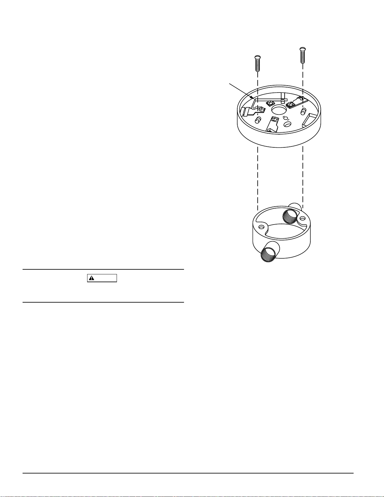
Mounting
Figure 1 shows mechanical mounting details. These detector bases mount to typical junction boxes. Attach the base
to the box using the screws supplied with the junction box.
Installation Guidelines
All wiring must be installed in compliance with applicable
codes and the authority having jurisdiction. Proper wire
gauges should be used. The conductors used to connect
smoke detectors to control panels and accessory devices
should be color-coded to reduce the likelihood of wiring errors. Improper connections can prevent a system from responding properly in the event of a fire.
For signal wiring (the wiring between interconnected detectors), it is recommended that the wire be no smaller
than 18 gauge. Wire sizes up to 12 gauge may be used with
the base. For best system performance, the power (+) and
(–) loop wires should be twisted pair and installed in separate grounded conduit to protect the loop from extraneous
electrical interference.
Smoke detectors and alarm system control panels have
specifications for allowable loop resistance. Consult the
control panel manufacturer’s specifications for the total
loop resistance allowed for the control panel being used before wiring the detector loops.
Figure 1. Mounting base to box:
SHORTING
SPRING
Wiring Instructions
CAUTION
Do not loop wire under terminals. Break wire run to ensure
supervision of connections.
Wire connections are made by stripping about 3/8" of insu-
lation from the end of the wire (use strip gauge molded in
base), sliding the bare end of the wire under the clamping
plate, and tightening the clamping plate screw.
Two-wire initiating devices receive their power from the
initiating circuit of a control panel. Electrical specifications
of the control panel and the detector-base combination
must be compatible for the system to function properly.
System Sensor maintains a list of two-wire detectors and
control panels that are listed as compatible. The 2-Wire
Compatibility Chart is available from System Sensor at no
charge.
A78-1468-01
D450-08-00 2 I56-338-07
Technical Manuals Online! - http://www.tech-man.com
Page 27
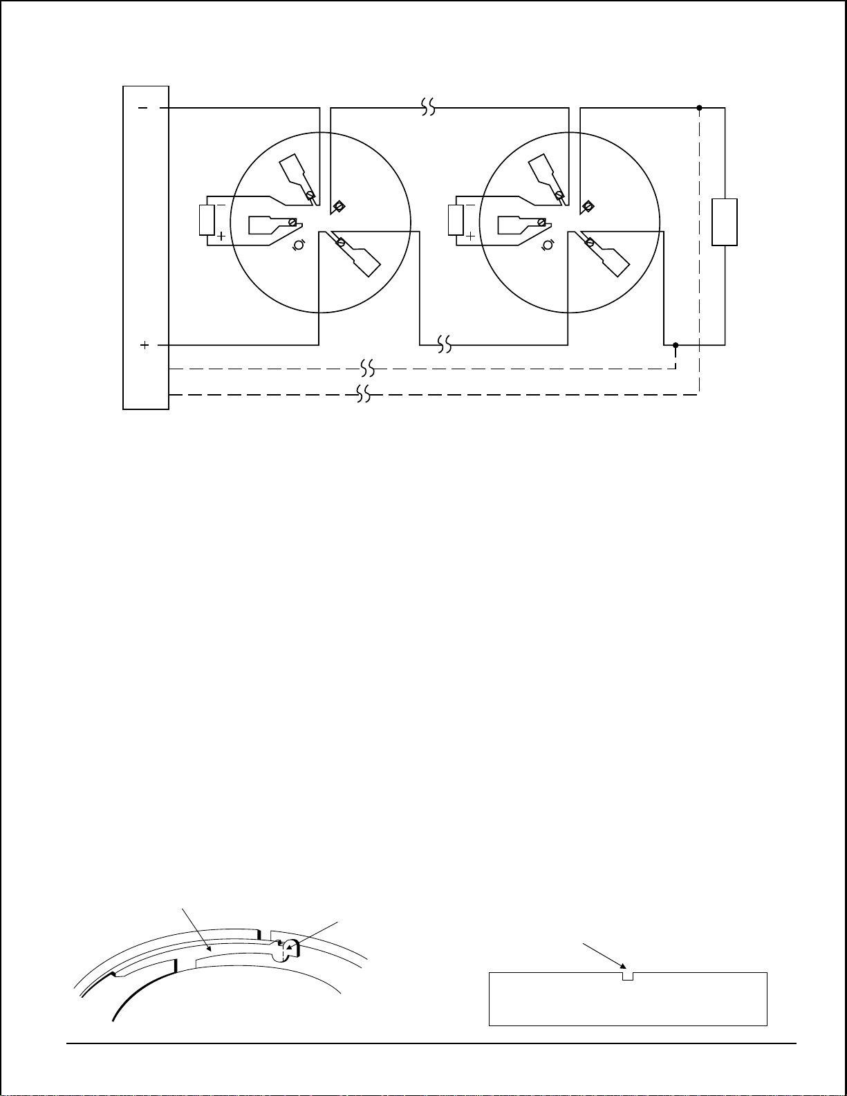
Figure 2. Typical 2-wire detector wiring configuration:
2
3
4
REMOTE
ANNUNCIATOR
2-WIRE CONTROL PANEL
1
5
The zone wiring of the detector bases should be checked
before the detector heads are installed. To make this
possible, this base contains a special spring-type shorting
jumper (shown in Figure 1). After a detector base is
properly wired and mounted to an electrical box, make
sure that the shorting spring is in contact with terminal 3.
This temporary connection permits the wiring of the loop
to be checked for continuity before installation of the
detector heads. The shorting spring in the base
automatically disengages when the detector head is
removed from the base. DO NOT remove the shorting
spring since it reengages as the detector head is turned in
the base, completing the circuit.
2
REMOTE
ANNUNCIATOR
CLASS A OPTIONAL WIRING
1
5
3
4
E
O
L
To make the detector tamper-resistant, remove the smaller
tab by breaking it at the scribed line on the tamper-resistant
tab before installing the detector (see Figure 3A). The
tamper-resistant tab is on the detector mounting base.
To remove a tamper-resistant detector from the base, use a
pocket screwdriver, or similar tool, to depress the tamperresistant tab and turn the detector counterclockwise. The
tab is accessible through the slot on the mounting base (see
Figure 3B).
The tamper-resistance feature can be defeated by breaking
and removing the plastic lever from the base. However, this
permanently disables the tamper-resistance feature.
A78-1175-04
Tamper-resistance Feature
This detector includes an optional tamper-resistance feature that prevents its removal from the base without the
use of a tool.
NOTE: DO NOT use the tamper-resistant feature if the XR-
5 removal tool is to be used.
Figure 3A. Activating tamper-resistance feature: Figure 3B. Removing detector head from base:
BREAK TAB AT
PLASTIC LEVER
D450-08-00 3 I56-338-07
DOTTED LINE BY
TWISTING TOWARD
CENTER OF BASE.
Technical Manuals Online! - http://www.tech-man.com
Optional Remote Annunciator Units
The model RA400Z remote LED annunciator is available as
an optional accessory. This unit has a rectangular plate that
fits U.S. single-gang light switch boxes. If a different type of
remote annunciator is used, it must be rated for the appropriate voltage, which is 2.75 to 3.0V.
USE SMALL-BLADED
SCREWDRIVER TO
PUSH PLASTIC LEVER
IN DIRECTION OF
ARROW.
A78-1468-02
Page 28

WARNING
The Limitations of Property Protection Smoke Detectors
The smoke detector used with this base is designed to activate and initiate emergency action, but will do so only when it is used in conjunction
with an authorized fire alarm system. This detector must be installed in
accordance with NFPA standard 72.
Smoke detectors will not work without power. AC or DC powered
smoke detectors will not work if the power supply is cut off.
Smoke detectors will not sense fires which start where smoke does not
reach the detectors. Smoldering fires typically do not generate a lot of
heat which is needed to drive the smoke up to the ceiling where the
smoke detector is usually located. For this reason, there may be large delays in detecting a smoldering fire with either an ionization type detector
or a photoelectric type detector. Either one of them may alarm only after
flaming has initiated which will generate the heat needed to drive the
smoke to the ceiling.
Smoke from fires in chimneys, in walls, on roofs or on the other side of a
closed door(s) may not reach the smoke detector and alarm it. A detector
cannot detect a fire developing on another level of a building quickly or at
all. For these reasons, detectors shall be located on every level and in
every bedroom within a building.
Smoke detectors have sensing limitations, too. Ionization detectors and
photoelectric detectors are required to pass fire tests of the flaming and
smoldering type. This is to ensure that both can detect a wide range of
types of fires. Ionization detectors offer a broad range of fire sensing capability, but they are somewhat better at detecting fast flaming fires than
slow smoldering fires. Photoelectric detectors sense smoldering fires better
than flaming fires which have little, if any, visible smoke. Because fires develop in different ways and are often unpredictable in their growth, neither type of detector is always best, and a given detector may not always
provide early warning of a specific type of fire.
In general, detectors cannot be expected to provide warnings for fires resulting from inadequate fire protection practices, violent explosions, escaping gases which ignite, improper storage of flammable liquids like
cleaning solvents which ignite, other similar safety hazards, arson, smoking in bed, children playing with matches or lighters, etc. Smoke detectors
used in high air velocity conditions may have a delay in alarm due to dilution of smoke densities created by frequent and rapid air exchanges. Additionally, high air velocity environments may create increased dust
contamination, demanding more frequent maintenance.
Smoke detectors cannot last forever. Smoke detectors contain electronic
parts. Even though smoke detectors are made to last over 10 years, any
part can fail at any time. Therefore, smoke detectors shall be replaced after
being in service for 10 years. The smoke detector system that this detector
is used in must be tested regularly per NFPA 72. This smoke detector
should be cleaned regularly per NFPA 72 or at least once a year.
Three-Year Limited Warranty
System Sensor warrants its enclosed smoke detector base to be free from
defects in materials and workmanship under normal use and service for a
period of three years from date of manufacture. System Sensor makes no
other express warranty for this smoke detector base. No agent, representative, dealer, or employee of the Company has the authority to increase or
alter the obligations or limitations of this Warranty. The Company’s obligation of this Warranty shall be limited to the repair or replacement of any
part of the smoke detector base which is found to be defective in materials
or workmanship under normal use and service during the three year period commencing with the date of manufacture. After phoning System
Sensor’s toll free number 800-SENSOR2 (736-7672) for a Return Authorization number, send defective units postage prepaid to: System Sensor,
D450-08-00 4 I56-338-07
Technical Manuals Online! - http://www.tech-man.com
Repair Department, RA #__________, 3825 Ohio Avenue, St. Charles, IL
60174. Please include a note describing the malfunction and suspected
cause of failure. The Company shall not be obligated to repair or replace
units which are found to be defective because of damage, unreasonable
use, modifications, or alterations occurring after the date of manufacture.
In no case shall the Company be liable for any consequential or incidental
damages for breach of this or any other Warranty, expressed or implied
whatsoever, even if the loss or damage is caused by the Company’s negligence or fault. Some states do not allow the exclusion or limitation of incidental or consequential damages, so the above limitation or exclusion may
not apply to you. This Warranty gives you specific legal rights, and you
may also have other rights which vary from state to state.
© System Sensor 1996
Page 29

INSTALLATION AND MAINTENANCE INSTRUCTIONS
B402B Plug-in Detector Base
For use with the following smoke detectors:
1451, 2451, and 2451TH
Specifications
Base Diameter: 6.2 inches (15.7 cm)
Base Height: 1.1 inches (2.8 cm)
Weight: 0.3 lb. (130 g)
Mounting: 4 inch square box with or without plaster ring. Min. Depth: 1.5 inches
4 inch octagon box. Min. Depth: 1.5 inches
3-1/2 inch octagon box. Min. Depth: 1.5 inches
Operating Temperature Range: 0° to +49°C (32° to 120°F)
Operating Humidity Range: 10% to 93 % Relative Humidity, Non-condensing
Electrical Ratings — includes base and detector
System Voltage: 24 VDC
Maximum Ripple Voltage: 4 Volts peak to peak
Start-up Capacitance: 0.02 µF Maximum
Standby Ratings: 20 VDC Minimum
29 VDC Maximum
120 µA Maximum
Alarm Ratings: 17 mA Minimum
36 mA Maximum
Reset Voltage: 1.4 VDC Minimum
Reset Time: 0.3 Seconds Maximum
(If used, the RA400 remote lamp operates within the specified
detector alarm currents.)
Start-up Time: 34.0 Seconds Maximum
Relay Contact Ratings
Resistive or Inductive (60% Power Factor):
Form A: 2.0A @ 30 VAC/DC
Form C: 2.0A @ 30 VAC/DC
0.6A @ 110 VDC
1.0A @ 125 VAC
3825 Ohio Avenue, St. Charles, Illinois 60174
1-800-SENSOR2, FAX: 630-377-6495
A Division of Pittway
Before Installing
Please read the System Sensor manual I56-407, Guide for
Proper Use of System Smoke Detectors, which provides de-
tailed information on detector spacing, placement, zoning,
wiring, and special applications. Copies of this manual are
available at no charge from System Sensor. (For installations in Canada, refer to CAN4-S524, Standard for the In-
stallation of Fire Alarm Systems, and CEC Part 1, Sec. 32.)
NOTICE: This manual should be left with the owner/user
of this equipment.
IMPORTANT: The detector used with this base must be
tested and maintained regularly following NFPA 72 requirements. The detector used with this base should be cleaned
at least once a year.
D450-03-00 1 I56-374-04
Technical Manuals Online! - http://www.tech-man.com
General Description
The plug-in detector base B402B is used with System Sensor model 2451 and 2451TH photoelectronic detector
heads, and model 1451 ionization detector head. The capability of plugging these detectors into a variety of special
bases makes them more versatile than equivalent directwired models. Refer to the System Sensor catalog for other
available plug-in detector bases.
This B402B base is intended for use in 4-wire systems, with
screw terminals provided for power, remote annunciator,
and relay contact connections. These bases also contain a
resistor to provide current limiting in the alarm state.
Page 30
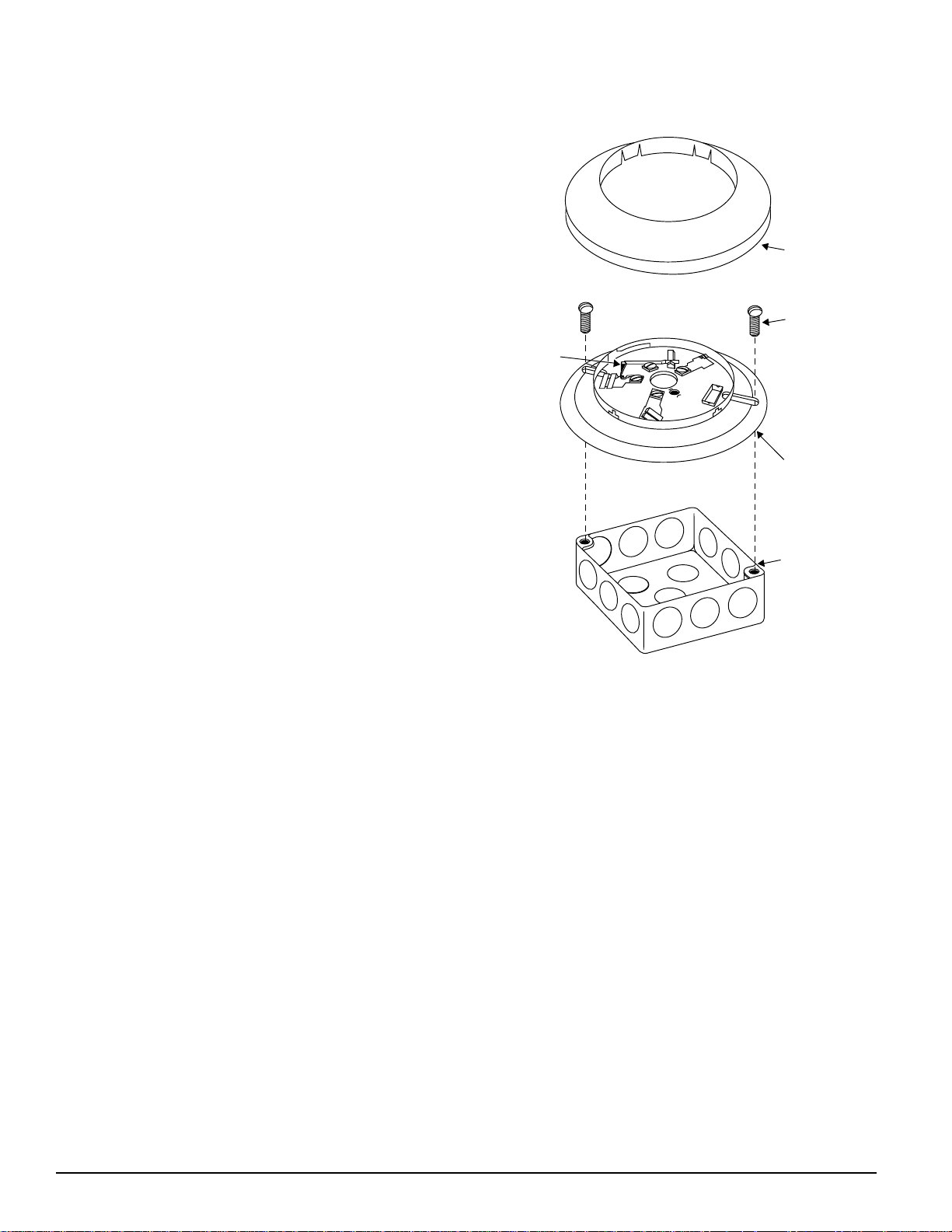
Mounting
This detector base mounts directly to 3-1/2-inch and 4-inch
octagon boxes, and 4-inch square boxes (with or without
plaster). To mount the base, remove the decorative ring by
rotating it in either direction to unhook the snaps before
separating the ring from the base. Use the screws supplied
with the junction box to attach the base to the box through
the appropriate slots in the base (see Figure 1). Position the
decorative ring around the base and rotate it in either direction until the ring snaps into place.
Installation Guidelines
All wiring must be installed in compliance with the National Electrical Code, all applicable local codes, and any
special requirements of the authority having jurisdiction,
using the proper wire size. The conductors used to connect
smoke detectors to control panels and accessory devices
should be color-coded to reduce the likelihood of wiring errors. Improper connections can prevent a system from responding properly in the event of a fire.
For signal wiring (the wiring between interconnected detectors), it is recommended that the wire be no smaller
than 18 gauge (1.0 square mm). The screws and clamping
plate in the base can accommodate wire sizes up to 12
gauge (2.5 square mm). For best system performance, the
power (+ and -) loop wire should be twisted pair and installed in separate grounded conduit to minimize the effects of electrical interference.
Figure 1. Mounting base to box:
SHORTING
SPRING
SNAP ON
DECORATIVE
RING
SCREWS (NOT
SUPPLIED)
DETECTOR
BASE
BOX (NOT
SUPPLIED)
Smoke detectors and alarm system control panels have
specifications for allowable loop resistance. Read the
manual for the control to determine the total loop resistance allowed before wiring the detector loops.
Locate installations where normal ambient temperature
does not exceed 100° F.
Wiring Instructions
Wire connections are made by stripping approximately 3/
8" (1 cm) insulation from the end of each wire, sliding the
bare end of the wire under the clamp plate, and tightening
the clamping plate screw. Use the strip gauges molded into
the inside and underside of the base for ease of wiring to
terminals 1 through 5 and to terminals 12 through 14, respectively.
The zone wiring of the detector base should be checked
before installing the smoke detector head. To make this
possible, this base contains a special-type shorting jumper.
After the detector base is wired and attached to the electrical box, make sure that the shorting spring is in contact
with the base of terminal 3. This temporary connection
A78-1175-01
shorts the positive-in and positive-out leads and permits
the wiring of the loop to be checked for continuity.
Once all the detector bases have been wired and mounted,
and the loop wiring has been checked, the detector heads
may be installed in the bases. The shorting spring in the
base will disengage automatically when the detector head
is removed from the base. DO NOT remove the shorting
spring since it reengages as the detector head is turned into
the base, completing the circuit.
D450-03-00 2 I56-374-04
Technical Manuals Online! - http://www.tech-man.com
Page 31
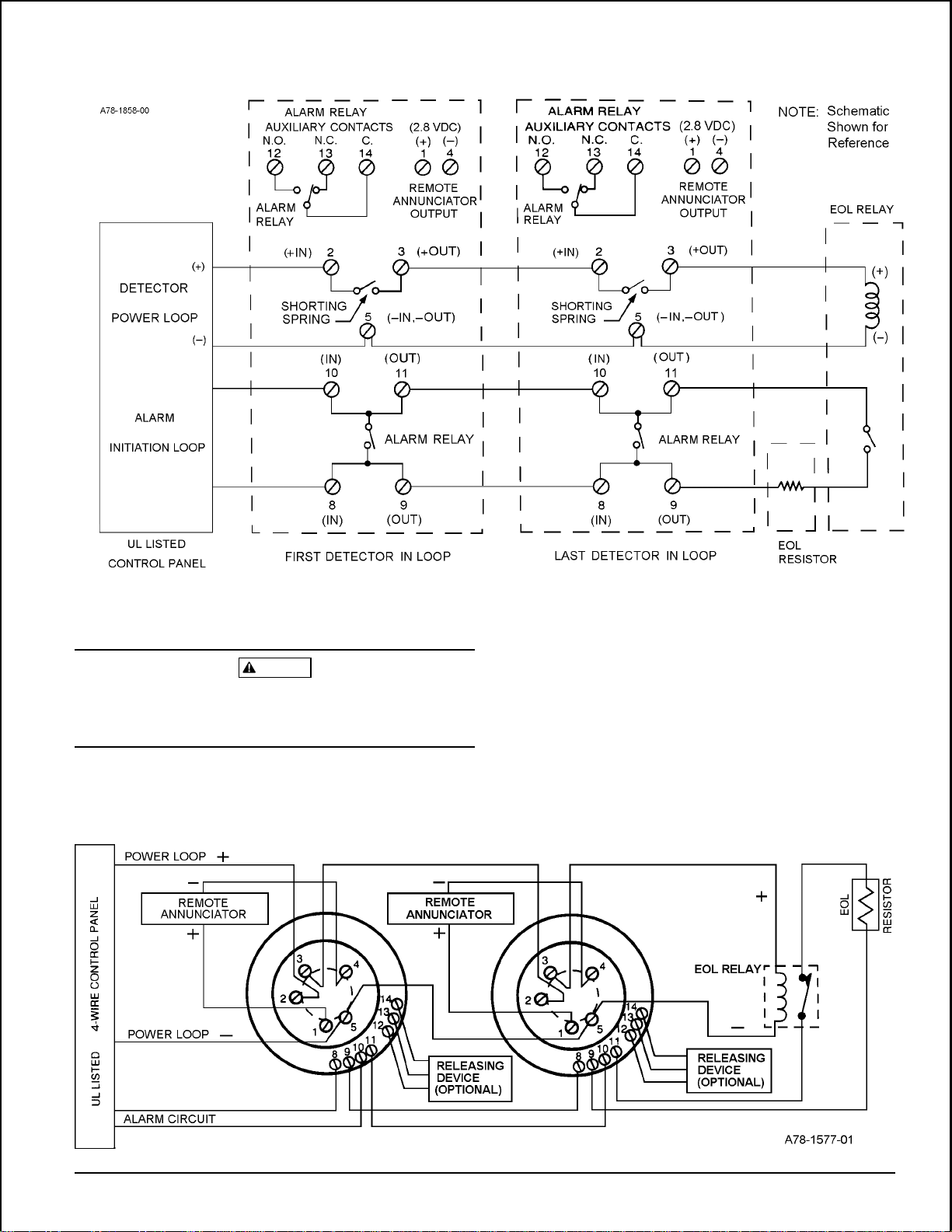
NOTE: For wiring or releasing device, refer to
manufacturer's installation instructions.
CAUTION
For system supervision–DO NOT use looped wire under terminals 2, 3, and 5. Break wire run to provide supervision of
system.
Figure 2. Typical wiring diagram:
D450-03-00 3 I56-374-04
Technical Manuals Online! - http://www.tech-man.com
Page 32

Tamperproof Feature
USE SMALL-BLADED
SCREWDRIVER TO
PUSH PLASTIC LEVER
IN DIRECTION OF
ARROW.
the small hole on the side of the base and push the plastic
lever away from the detector head (see Figure 3B). This
CAUTION
will allow the detector to be rotated counterclockwise for
removal.
Do not use the tamperproof feature if the XR5 removal tool
is to be used.
NOTE: Head removal after the tamperproof feature has
been activated first requires removal of the decora-
This detector base can be made tamperproof to prevent the
tive ring.
removal of the detector head without the use of a tool. To
activate this feature, break off the tab on the detector base
as shown in Figure 3A, then install the detector. To remove
the detector from the base once the tamperproof feature
The tamperproof feature may be defeated by breaking and
removing the plastic lever from the base; however, this prevents ever using the feature again.
has been activated, place a small-bladed screwdriver into
Figure 3A. Activating tamperproof feature: Figure 3B. Removing detector head from base:
BREAK TAB AT
PLASTIC LEVER
DOTTED LINE BY
TWISTING TOWARD
CENTER OF BASE.
A78-1175-03A
WARNING
The Limitations of Property Protection Smoke Detectors
The smoke detector used with this base is designed to activate and initiate emergency action, but will do so only when it is used in conjunction
with an authorized fire alarm system. This detector must be installed in
accordance with NFPA standard 72.
Smoke detectors will not work without power. AC or DC powered
smoke detectors will not work if the power supply is cut off.
Smoke detectors will not sense fires which start where smoke does not
reach the detectors. Smoldering fires typically do not generate a lot of
heat which is needed to drive the smoke up to the ceiling where the
smoke detector is usually located. For this reason, there may be large delays in detecting a smoldering fire with either an ionization type detector
or a photoelectric type detector. Either one of them may alarm only after
flaming has initiated which will generate the heat needed to drive the
smoke to the ceiling.
Smoke from fires in chimneys, in walls, on roofs or on the other side of a
closed door(s) may not reach the smoke detector and alarm it. A detector
cannot detect a fire developing on another level of a building quickly or at
all. For these reasons, detectors shall be located on every level and in
every bedroom within a building.
Smoke detectors have sensing limitations, too. Ionization detectors and
photoelectric detectors are required to pass fire tests of the flaming and
smoldering type. This is to ensure that both can detect a wide range of
Three-Year Limited Warranty
System Sensor warrants its enclosed smoke detector base to be free from
defects in materials and workmanship under normal use and service for a
period of three years from date of manufacture. System Sensor makes no
other express warranty for this smoke detector base. No agent, representative, dealer, or employee of the Company has the authority to increase or
alter the obligations or limitations of this Warranty. The Company’s obligation of this Warranty shall be limited to the repair or replacement of any
part of the smoke detector base which is found to be defective in materials
or workmanship under normal use and service during the three year period commencing with the date of manufacture. After phoning System
Sensor’s toll free number 800-SENSOR2 (736-7672) for a Return Authorization number, send defective units postage prepaid to: System Sensor,
D450-03-00 4 I56-374-04
Technical Manuals Online! - http://www.tech-man.com
types of fires. Ionization detectors offer a broad range of fire sensing capability but they are somewhat better at detecting fast flaming fires than
slow smoldering fires. Photoelectric detectors sense smoldering fires better
than flaming fires which have little, if any, visible smoke. Because fires develop in different ways and are often unpredictable in their growth, neither type of detector is always best, and a given detector may not always
provide early warning of a specific type of fire.
In general, detectors cannot be expected to provide warnings for fires resulting from inadequate fire protection practices, violent explosions, escaping gases which ignite, improper storage of flammable liquids like
cleaning solvents which ignite, other similar safety hazards, arson, smoking in bed, children playing with matches or lighters, etc. Smoke detectors
used in high air velocity conditions may have a delay in alarm due to dilution of smoke densities created by frequent and rapid air exchanges. Additionally, high air velocity environments may create increased dust
contamination, demanding more frequent maintenance.
Smoke detectors cannot last forever. Smoke detectors contain electronic
parts. Even though smoke detectors are made to last over 10 years, any
part can fail at any time. Therefore, smoke detectors shall be replaced after
being in service for 10 years. The smoke detector system that this detector
is used in must be tested regularly per NFPA 72. This smoke detector
should be cleaned regularly per NFPA 72 or at least once a year.
Repair Department, RA #__________, 3825 Ohio Avenue, St. Charles, IL
60174. Please include a note describing the malfunction and suspected
cause of failure. The Company shall not be obligated to repair or replace
units which are found to be defective because of damage, unreasonable
use, modifications, or alterations occurring after the date of manufacture.
In no case shall the Company be liable for any consequential or incidental
damages for breach of this or any other Warranty, expressed or implied
whatsoever, even if the loss or damage is caused by the Company’s negligence or fault. Some states do not allow the exclusion or limitation of incidental or consequential damages, so the above limitation or exclusion may
not apply to you. This Warranty gives you specific legal rights, and you
may also have other rights which vary from state to state.
© System Sensor 1996
A78-1175-03B
Page 33

INSTALLATION AND MAINTENANCE INSTRUCTIONS
B404B Plug-in Detector Base
For use with 1451, 2451, AND 2451TH detectors
Specifications
Base Diameter: 6.2 inches (15.7 cm)
Base Height: 0.95 inches (2.9cm)
Weight: 0.6 lb. (260 g)
Mounting: 4-inch square box with or without plaster ring. Min. depth–1.5 inches
4-inch octagon box. Min. depth–1.5 inches
3-1/2-inch octagon box. Min. depth–1.5 inches
Operating Temperature Range: 0° to 49°C (32° to 120°F)
Operating Humidity Range: 10% to 93% Relative Humidity
Electrical Ratings - includes base and detector
System Voltage: 120 VAC, 60 Hz
Relay Contact Ratings
Resistive or Inductive (60% power factor) load
Form A: 2.0A @ 30VAC/DC
Form C: 2.0A @ 30VAC/DC
0.6A @ 110VDC
1.0A @ 125VAC
(If used, the RA400 Remote Lamp operates within the specified detector system voltage.)
Start-up Time: 36.0 Seconds maximum
(After 60 second reset)
3825 Ohio Avenue, St. Charles, Illinois 60174
1-800-SENSOR2, FAX: 630-377-6495
A Division of Pittway
Before Installing
Please thoroughly read the System Sensor manual I56-407,
Guide for Proper Use of System Smoke Detectors. This
manual provides detailed information on detector spacing,
placement, zoning, wiring, and special applications, and is
available at no charge from System Sensor. (For installation
in Canada, refer to CAN/ULC-S524, Standard for the Instal-
lation of Fire Alarm Systems and CEC Part 1, Sec. 32.)
NOTICE: This manual should be left with the owner/user
of this equipment.
IMPORTANT: The detector used with this base must be
tested and maintained regularly following NFPA 72 requirements. The detector should be cleaned at least once a year.
General Description
The B404B detector base is designed for use with System
Sensor model 2451 and 2451TH photoelectronic and 1451
ionization detector heads. The capability of plugging these
detectors into a variety of special bases makes them more
versatile than equivalent direct-wired models. Refer to the
System Sensor catalog for other available plug-in bases.
The B404B base is intended for use in 4-wire systems with
terminals provided for power, remote annunicator, and relay connections. This base also contains a resistor to provide current limiting in the alarm state.
D450-04-00 1 I56-375-03
Technical Manuals Online! - http://www.tech-man.com
Page 34

Base Terminals
No. Function
1 Remote Annunciator (+)
2 Test Coil (+)
3 Not used
4 Remote Annunciator (–)
5 RTC (–)
6 N.O. Supervisory Relay
7 N.O Form A Contacts
8 N.O. Alarm Relay
9 N.O. Form A
10 C. Initiation
11 C. Contacts
12 N.O. Alarm Relay
13 N.C. Form C
14 C. Auxiliary Contacts
Mounting
The detector base mounts directly to 3-1/2 inch and 4-inch
octagon boxes and 4-inch square boxes, with or without
plaster rings. To mount the base, remove the decorative
ring by rotating it in either direction to unhook the snaps
before separating the ring from the base. Use the screws
supplied with the junction box to attach the base to the box
through the appropriate mounting slots in the base.
}
}
}
Figure 1. Base terminals:
Figure 2. Mounting base to box:
Position the decorative ring around the base and rotate it in
either direction until the ring snaps into place (please see
Figure 2).
Installation Guidelines
All wiring must be installed in compliance with the National Electrical Code, all applicable local codes, and any
special requirements of the authority having jurisdiction,
using the proper wire size. The conductors used to connect
smoke detectors to control panels and accessory devices
should be color-coded to reduce the likelihood of wiring errors. Improper connections can prevent a system from responding properly in the event of a fire.
For signal wiring (the wiring between interconnected detectors), it is recommended that the wire be no smaller
than 16 gauge (1.5 square mm), and that two- or three-conductor wire be no smaller than 18 gauge (1.0 square mm).
For best performance, alarm loop conductors should be installed in separate grounded conduit or shielded cable to
protect the alarm loop from extraneous electrical interference.
SNAP ON
DECORATIVE
RING
SCREWS (NOT
SUPPLIED)
SHORTING
SPRING
DETECTOR
BASE
BOX (NOT
SUPPLIED)
Smoke detectors and alarm systems control panels have
specifications for allowable loop resistance. Consult the
control panel manufacturer’s specifications for the total
loop resistance allowed for the particular model control
panel being used before wiring the detector loops.
D450-04-00 2 I56-375-03
Technical Manuals Online! - http://www.tech-man.com
A78-1175-01
Page 35

Figure 3. Typical wiring diagram for 120VAC detector systems:
Locate installations where normal ambient temperatures do
not exceed 100°F.
Wiring Instructions
NOTE: Refer to the manufacturer’s instructions for releas-
ing device wiring.
NOTE: To ensure that electrical connections are super-
vised, do NOT loop wires under terminals 8, 9, 10,
and 11. Cut the wire at each terminal.
To make electrical connections, strip approximately 3/8" (1
cm) insulation from the end of each wire, slide the bare
wire end under the clamping plate, and tighten the clamping plate screw. Use the strip gauges molded into the inside and underside of the base for ease of wiring to
terminals 1 and 4, and to terminals 6 through 14, respectively.
The zone wiring of the detector base should be checked
before installing the smoke detector heads. The base con-
tains a built-in shorting spring to make this possible. After
the detector base is wired and mounted to an electrical box,
position the shorting spring against terminal 3. This temporary connection energizes the supervisory relay and permits the wiring of the loop to checked for continuity.
After all detector bases have been mounted, wired, and the
wiring checked, install the detector heads. The shorting
spring in the base automatically disengages when the detector head is removed from the base. DO NOT remove the
shorting spring since it reengages as the detector head is
turned into the base, completing the circuit.
Tamper-resistance Feature
This detector base can be made tamper resistant so it cannot be removed without the use of a tool. To make the base
tamper resistant, simply break off the tab on the base (see
Figure 4A), before installing the detector.
D450-04-00 3 I56-375-03
Technical Manuals Online! - http://www.tech-man.com
Page 36

To remove the detector from the base after it has been made
tamper resistant, insert a small screwdriver (please see Figure 4B) into the small hole and press the plastic lever away
NOTE: Head removal after activating the tamper-resis-
tance feature first requires removal of the decora-
tive ring.
from the detector. Rotate the detector counterclockwise
and remove.
Figure 4A. Activating tamper-resistance feature: Figure 4B. Removing detector head from base:
BREAK TAB AT
PLASTIC LEVER
The smoke detector used with this base is designed to activate and initiate emergency action, but will do so only when it is used in conjunction
with an authorized fire alarm system. This detector must be installed in
accordance with NFPA standard 72.
Smoke detectors will not work without power. AC or DC powered
smoke detectors will not work if the power supply is cut off.
Smoke detectors will not sense fires which start where smoke does not
reach the detectors. Smoldering fires typically do not generate a lot of
heat which is needed to drive the smoke up to the ceiling where the
smoke detector is usually located. For this reason, there may be large delays in detecting a smoldering fire with either an ionization type detector
or a photoelectric type detector. Either one of them may alarm only after
flaming has initiated which will generate the heat needed to drive the
smoke to the ceiling.
Smoke from fires in chimneys, in walls, on roofs or on the other side of a
closed door(s) may not reach the smoke detector and alarm it. A detector
cannot detect a fire developing on another level of a building quickly or at
all. For these reasons, detectors shall be located on every level and in
every bedroom within a building.
Smoke detectors have sensing limitations, too. Ionization detectors and
photoelectric detectors are required to pass fire tests of the flaming and
DOTTED LINE BY
TWISTING TOWARD
CENTER OF BASE.
The Limitations of Property Protection Smoke Detectors
USE SMALL-BLADED
SCREWDRIVER TO
PUSH PLASTIC LEVER
IN DIRECTION OF
ARROW.
WARNING
smoldering type. This is to ensure that both can detect a wide range of
types of fires. Ionization detectors offer a broad range of fire sensing capability, but they are somewhat better at detecting fast flaming fires than
slow smoldering fires. Photoelectric detectors sense smoldering fires better
than flaming fires which have little, if any, visible smoke. Because fires develop in different ways and are often unpredictable in their growth, neither type of detector is always best, and a given detector may not always
provide early warning of a specific type of fire.
In general, detectors cannot be expected to provide warnings for fires resulting from inadequate fire protection practices, violent explosions, escaping gases which ignite, improper storage of flammable liquids like
cleaning solvents which ignite, other similar safety hazards, arson, smoking in bed, children playing with matches or lighters, etc. Smoke detectors
used in high air velocity conditions may have a delay in alarm due to dilution of smoke densities created by frequent and rapid air exchanges. Additionally, high air velocity environments may create increased dust
contamination, demanding more frequent maintenance.
Smoke detectors cannot last forever. Smoke detectors contain electronic
parts. Even though smoke detectors are made to last over 10 years, any
part can fail at any time. Therefore, smoke detectors shall be replaced after
being in service for 10 years. The smoke detector system that this detector
is used in must be tested regularly per NFPA 72. This smoke detector
should be cleaned regularly per NFPA 72 or at least once a year.
A78-1175-03
Three-Year Limited Warranty
System Sensor warrants its enclosed smoke detector base to be free from
defects in materials and workmanship under normal use and service for a
period of three years from date of manufacture. System Sensor makes no
other express warranty for this smoke detector base. No agent, representative, dealer, or employee of the Company has the authority to increase or
alter the obligations or limitations of this Warranty. The Company’s obligation of this Warranty shall be limited to the repair or replacement of any
part of the smoke detector base which is found to be defective in materials
or workmanship under normal use and service during the three year period commencing with the date of manufacture. After phoning System
Sensor’s toll free number 800-SENSOR2 (736-7672) for a Return Authorization number, send defective units postage prepaid to: System Sensor,
D450-04-00 4 I56-375-03
Technical Manuals Online! - http://www.tech-man.com
Repair Department, RA #__________, 3825 Ohio Avenue, St. Charles, IL
60174. Please include a note describing the malfunction and suspected
cause of failure. The Company shall not be obligated to repair or replace
units which are found to be defective because of damage, unreasonable
use, modifications, or alterations occurring after the date of manufacture.
In no case shall the Company be liable for any consequential or incidental
damages for breach of this or any other Warranty, expressed or implied
whatsoever, even if the loss or damage is caused by the Company’s negligence or fault. Some states do not allow the exclusion or limitation of incidental or consequential damages, so the above limitation or exclusion may
not apply to you. This Warranty gives you specific legal rights, and you
may also have other rights which vary from state to state.
© System Sensor 1996
Page 37

INSTALLATION AND MAINTENANCE INSTRUCTIONS
B406B Plug-in Detector Base
For use with the following smoke detectors:
In US: 1451, 2451, 2451TH, 4451HT, 5451
In Canada: 1451A, 2451A, 2451THA, 4451HTA, 5451A
In Europe: 1451E, 2451E, 4451E, 5451E
Specifications
Base Diameter: 6.2 inches (15.7 cm)
Base Height: 1.1 inches (2.9 cm)
Weight: 0.3 lb. (130 g)
Mounting: 4-inch square box with or without plaster ring. Min. Depth–1.5 inches
4-inch octagon box. Min. Depth–1.5 inches
3-1/2-inch octagon box. Min. Depth–1.5 inches
50 mm box; 60 mm box; 70 mm box
Operating Temperature Range: -10° to 60°C (14° to 140°F)
Note: Do not install in locations where normal ambient temperature
exceeds 50°C (120°F)
Operating Humidity Range: 10% to 93% Relative Humidity
Electrical Ratings – includes base and detector
System Voltage: 24 VDC
Maximum Ripple Voltage: 4 Volts peak to peak
Start-up Capacitance: 0.02µF Maximum
Standby Ratings: 15 VDC Minimum
35 VDC Maximum
120 µA Maximum
Alarm Ratings: 8 V Minimum at 16 mA
12 V Maximum at 100 mA
(Alarm current MUST be limited to 100 mA maximum by the control panel.)
Relay Contact Ratings:
Resistive or Inductive (60% power factor) Load
Form C*: 2.0A @ 30 VAC/DC
0.6A @ 110 VDC
1.0A @ 125 VAC
Reset Voltage: 1.4 VDC Minimum
Reset Time: 0.3 Seconds Maximum
Start-up Time: 34.0 Seconds Maximum
*For Canadian installations relay contact ratings are 2.0A @ 30 VAC/DC.
3825 Ohio Avenue, St. Charles, Illinois 60174
1-800-SENSOR2, FAX: 630-377-6495
A Division of Pittway
Before Installing
Please thoroughly read the System Sensor manual I56-407,
Guide for Proper Use of System Smoke Detectors, which provides detailed information on detector spacing, placement,
zoning, wiring, and special applications. Copies of this
manual are available at no charge from System Sensor. (For
installations in Canada, please refer to CAN4-S524, Standard for the Installation of Fire Alarm Systems and CEC
Part 1, Sec. 32.)
NOTICE: This manual should be left with the owner/user
of this equipment.
IMPORTANT: The detector used with this base must be
tested and maintained regularly following NFPA 72 require-
D450-05-00 1 I56-376-06
Technical Manuals Online! - http://www.tech-man.com
ments. The detector used with this base should be cleaned
at least once a year.
General Description
The B406B plug-in detector base is used with a variety of
System Sensor conventional detector heads. They are capable of accepting a variety of detector heads, which makes
them more versatile than equivalent direct-wired models.
Refer to the System Sensor catalog for other available plugin detector bases.
The B406B base is intended for use in 2-wire systems, with
screw terminals provided for power and relay contact connections. These bases MUST be current limited by the system control panel in the alarm state.
Page 38

Mounting
This detector base mounts directly to 3-1/2-inch and 4inch octagon boxes, and 4-inch square boxes (with or without plaster rings). To mount, remove decorative ring by
turning it in either direction to unhook the snaps, then
separate the ring from the base. Install the base to the box
using the screws supplied with the junction box and the appropriate mounting slots in the base. Place decorative ring
onto base, then turn in either direction until the ring snaps
in place (see Figure 1).
Installation Guidelines
All wiring must be installed in compliance with the National Electrical Code and the local codes having jurisdiction.
Proper wire gauges should be used. The conductors used to
connect smoke detectors to control panels and accessory
devices should be color-coded to prevent wiring mistakes.
Improper connections can prevent a system from responding properly in the event of a fire.
Figure 1. Mounting base to box:
SHORTING
SPRING
SNAP ON
DECORATIVE
RING
SCREWS (NOT
SUPPLIED)
For signal wiring (the wiring between interconnected detectors), it is recommended that the wire be no smaller
than 18 gauge. Wire sizes up to 12 gauge may be used with
the base. For best system performance, the power (+) and
(–) loop wires should be twisted pair and installed in separate grounded conduit to protect the loop from extraneous
electrical interference.
Smoke detectors and alarm system control panels have
specifications for allowable loop resistance. Consult the
control panel manufacturer’s specifications for the total
loop resistance of the particular model control panel being
used before wiring the detector loops.
Wiring Instructions
CAUTION
For system supervision — For terminals 2, 3, and 5 do not
use looped wire under terminals. Break wire run to provide
system supervision of connections.
Wire connections are made by simply stripping insulation
from the end of the wire, sliding the bare end of the wire
under the clamping plate, and tightening the clamping
plate screw. Use the strip gauges molded into the inside
and underside of the base for ease of wiring to terminals 1
through 5, and to terminals 12 through 14, respectively.
System Sensor smoke detectors and mounting bases are
marked with a compatibility identifier located as the last
digit of a five digit code stamped on the back of the product. Connect detectors/mounting bases only to compatible
control units as indicated in System Sensor’s compatibility
chart which contains a current list of UL listed control units
DETECTOR
BASE
BOX (NOT
SUPPLIED)
A78-1175-01
and detector head/base combinations. A copy of this list is
available from System Sensor upon request.
The zone wiring of the detector base should be checked
before the detector heads are installed in them. To make
this possible, this base contains a special spring-type shorting jumper. After a detector base is properly wired and
mounted on an electrical box, make sure that the jumper
spring is in contact with the base of Terminal 3. This temporary connection shorts the positive-in and positive-out
leads and permits the wiring of the loop to be checked for
continuity.
Once all the detector bases have been wired and mounted,
and the loop wiring has been checked, the detector heads
may be installed in the bases. The shorting spring in the
base will disengage automatically when the detector head
is removed from the base. DO NOT remove the shorting
spring since it reengages as the detector head is turned into
the base, completing the circuit.
D450-05-00 2 I56-376-06
Technical Manuals Online! - http://www.tech-man.com
Page 39

Figure 2. Typical wiring diagram:
(+) POWER LOOP
3
2
2-WIRE CONTROL PANEL
(–) POWER LOOP
CLASS A OPTIONAL WIRING
Tamper-resistance Feature
CAUTION
Do not use the tamper-resistance feature if the XR5 removal
tool is to be used.
This detector base includes an optional tamper-resistance
feature that, when activated, prevents removal of the detector without the use of a tool.
To activate this feature, simply break off the tab on the detector base shown in Figure 3A, then install the detector. To
remove the detector from the base once the tamper-resistance feature has been activated, place a small-bladed
screwdriver into the small hole on the side of the base and
4
E
O
14
COM CONTACT
N.C. AUXILIARY
12
13
N.O. FORM C
5
1
L
push plastic lever away from the detector head (see Figure
3B). This will allow the detector to be rotated counterclockwise for removal.
NOTE: Head removal after the tamper-resistance feature
has been activated first requires removal of the
decorative ring.
The tamper-resistance feature may be defeated by breaking
and removing the plastic lever from the base, however this
prevents ever using the feature again.
A78-1577-00
Figure 3A. Activating tamper-resistance feature: Figure 3B. Removing detector head from base:
BREAK TAB AT
PLASTIC LEVER
D450-05-00 3 I56-376-06
DOTTED LINE BY
TWISTING TOWARD
CENTER OF BASE.
Technical Manuals Online! - http://www.tech-man.com
USE SMALL-BLADED
SCREWDRIVER TO
PUSH PLASTIC LEVER
IN DIRECTION OF
ARROW.
A78-1175-03
Page 40

WARNING
The Limitations of Property Protection Smoke Detectors
The smoke detector used with this base is designed to activate and initiate emergency action, but will do so only when it is used in conjunction
with an authorized fire alarm system. This detector must be installed in
accordance with NFPA standard 72.
Smoke detectors will not work without power. AC or DC powered
smoke detectors will not work if the power supply is cut off.
Smoke detectors will not sense fires which start where smoke does not
reach the detectors. Smoldering fires typically do not generate a lot of
heat which is needed to drive the smoke up to the ceiling where the
smoke detector is usually located. For this reason, there may be large delays in detecting a smoldering fire with either an ionization type detector
or a photoelectric type detector. Either one of them may alarm only after
flaming has initiated which will generate the heat needed to drive the
smoke to the ceiling.
Smoke from fires in chimneys, in walls, on roofs or on the other side of a
closed door(s) may not reach the smoke detector and alarm it. A detector
cannot detect a fire developing on another level of a building quickly or at
all. For these reasons, detectors shall be located on every level and in
every bedroom within a building.
Smoke detectors have sensing limitations, too. Ionization detectors and
photoelectric detectors are required to pass fire tests of the flaming and
smoldering type. This is to ensure that both can detect a wide range of
types of fires. Ionization detectors offer a broad range of fire sensing capability but they are somewhat better at detecting fast flaming fires than
slow smoldering fires. Photoelectric detectors sense smoldering fires better
than flaming fires which have little, if any, visible smoke. Because fires develop in different ways and are often unpredictable in their growth, neither type of detector is always best, and a given detector may not always
provide early warning of a specific type of fire.
In general, detectors cannot be expected to provide warnings for fires resulting from inadequate fire protection practices, violent explosions, escaping gases which ignite, improper storage of flammable liquids like
cleaning solvents which ignite, other similar safety hazards, arson, smoking in bed, children playing with matches or lighters, etc. Smoke detectors
used in high air velocity conditions may have a delay in alarm due to dilution of smoke densities created by frequent and rapid air exchanges. Additionally, high air velocity environments may create increased dust
contamination, demanding more frequent maintenance.
Smoke detectors cannot last forever. Smoke detectors contain electronic
parts. Even though smoke detectors are made to last over 10 years, any
part can fail at any time. Therefore, smoke detectors shall be replaced after
being in service for 10 years. The smoke detector system that this detector
is used in must be tested regularly per NFPA 72. This smoke detector
should be cleaned regularly per NFPA 72 or at least once a year.
Three-Year Limited Warranty
System Sensor warrants its enclosed smoke detector base to be free from
defects in materials and workmanship under normal use and service for a
period of three years from date of manufacture. System Sensor makes no
other express warranty for this smoke detector base. No agent, representative, dealer, or employee of the Company has the authority to increase or
alter the obligations or limitations of this Warranty. The Company’s obligation of this Warranty shall be limited to the repair or replacement of any
part of the smoke detector base which is found to be defective in materials
or workmanship under normal use and service during the three year period commencing with the date of manufacture. After phoning System
Sensor’s toll free number 800-SENSOR2 (736-7672) for a Return Authorization number, send defective units postage prepaid to: System Sensor,
D450-05-00 4 I56-376-06
Technical Manuals Online! - http://www.tech-man.com
Repair Department, RA #__________, 3825 Ohio Avenue, St. Charles, IL
60174. Please include a note describing the malfunction and suspected
cause of failure. The Company shall not be obligated to repair or replace
units which are found to be defective because of damage, unreasonable
use, modifications, or alterations occurring after the date of manufacture.
In no case shall the Company be liable for any consequential or incidental
damages for breach of this or any other Warranty, expressed or implied
whatsoever, even if the loss or damage is caused by the Company’s negligence or fault. Some states do not allow the exclusion or limitation of incidental or consequential damages, so the above limitation or exclusion may
not apply to you. This Warranty gives you specific legal rights, and you
may also have other rights which vary from state to state.
© System Sensor 1996
Page 41

INSTALLATION AND MAINTENANCE INSTRUCTIONS
B401R Plug-in Detector Base
For use with the following smoke detectors: 1451E and 2451E
Specifications
Diameter: 10.2 cm (4.0 inches)
Height: 2.0 cm (0.8 inches)
Weight: 152 g (0.34 lb.)
Operating Temperature: –10° to +60°C (14° to 140°F)
Operating Humidity: 10% to 93% Relative Humidity
Electrical Ratings — includes base and detector
Voltage: 24 VDC
Maximum Ripple Voltage: 4 Volts peak to peak
Start-up Capacitance: 0.02 µF Maximum
Standby Ratings: 15 VDC Minimum
32 VDC Maximum
120 µA Maximum
Alarm Ratings: 10 mA Minimum at 10.5 VDC
62mA Maximum at 32 VDC
(If used, the RA400Z Remote Annunciator operates within the specified
detector alarm currents.)
Reset Voltage: 2.5 VDC Minimum
A Division of Pittway
System Sensor Europe
Via Caboto 19, 34143, Trieste, Italy
Before Installing
Please thoroughly read the System Sensor Manual I56-407,
Guide For Proper Use of System Smoke Detectors, which provides detailed information on detector spacing, placement,
zoning, wiring, and special applications. Copies of this
manual are available at no charge from System Sensor.
NOTICE: This manual should be left with the owner/user
of this equipment.
IMPORTANT: The detector used with this base must be
tested and maintained regularly following NFPA 72 requirements. The detector used with this base should be cleaned
at least once a year.
General Description
The B401R plug-in detector base is used with System Sensor model 2451E photoelectronic detector head and model
1451E ionization detector head. The capability of plugging
these detectors into a variety of special bases makes them
more versatile than equivalent direct-wired models. Refer
to the System Sensor catalog for other plug-in detector
bases.
The B401R base is intended for use in 2-wire systems, with
screw terminals provided for power, ground, and remote
annunciator connections. The B401R base also contains a
resistor to provide current limiting in the alarm state.
Technical Manuals Online! - http://www.tech-man.com
1 I56-351-03
Page 42
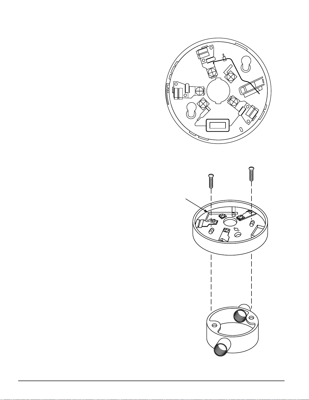
Base Terminals
NO. FUNCTION
1 REMOTE ANNUNCIATOR (+)
2 NEGATIVE (–) V IN, REMOTE ANNUNCIATOR (–)
3 NEGATIVE (–) V OUT
4 NOT USED
5 POSITIVE (+) V IN AND V OUT
NOTE: If remote annunciator is not used, polarity to these
terminals may be reversed.
Mounting
These detector bases mount to typical junction boxes. Install the base to the box using the screws supplied with the
junction box. Figure 2 shows mechanical mounting details.
Wiring Installation Guidelines
All wiring must be installed in compliance with the National Electrical Code and the local codes having jurisdiction. Proper wire gauges should be used. The conductors
used to connect smoke detectors to control panels and accessory devices should be color-coded to prevent wiring
mistakes. Improper connections can prevent a system from
responding properly in the event of a fire.
For signal wiring, (the wiring between interconnected detectors or from detectors to auxiliary devices), it is recommended that single-conductor wire be no smaller than
1.5mm2, and that two- or three-conductor wire be no
smaller than 1.0mm2. For best system performance, alarm
loop conductors should be installed in separate grounded
conduit or shielded cable to protect the alarm loop from extraneous electrical interference.
Figure 1. Terminal layout:
3
2
1
5
4
Figure 2. Mounting base to box:
SHORTING
SPRING
A78-1468-03
Smoke detectors and alarm system control panels have
specifications for allowable loop resistance. Consult the
control panel manufacturer’s specifications for the total
loop resistance allowed for the particular model control
panel being used before wiring the detector loops.
Wiring Instructions
Wire connections are made by stripping about 1 cm (3/8")
of insulation from the end of the wire (use strip gauge
molded in base), sliding the bare end of the wire under the
clamping plate, and tightening the clamping plate screw.
The zone wiring of the detector bases should be checked
before the detector heads are installed. To make this
possible, this base contains a special spring-type shorting
jumper (shown in Figure 2). After a detector base is
properly wired and mounted to an electrical box, make
sure that the shorting spring is in contact with terminal 3.
Technical Manuals Online! - http://www.tech-man.com
A78-1468-01
2 I56-351-03
Page 43
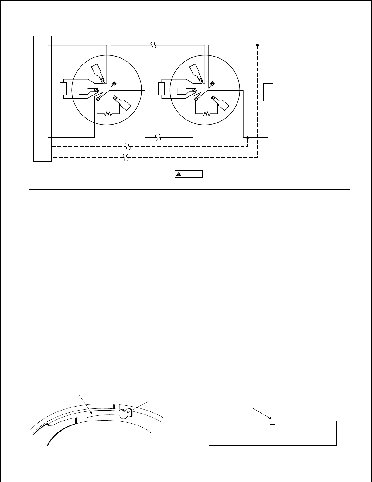
REMOTE
ANNUNCIATOR
2
1
3
5
4
+
–
2-WIRE CONTROL PANEL
+
–
REMOTE
ANNUNCIATOR
2
1
3
5
4
+
–
E
O
L
CLASS A OPTIONAL WIRING
NOTE: IF REMOTE ANNUNCIATOR
IS NOT USED, POLARITY TO
THESE TERMINALS MAY BE
REVERSED.
Figure 3. Typical wiring diagram for 2-wire detector system:
CAUTION
Do not loop wire under terminals. Break wire run to provide supervision of connections.
A78-1175-05
This temporary connection permits the wiring of the loop
to be checked for continuity before installation of the
detector heads.
To activate this feature, break off the tab on the detector
base (see Figure 4), then install the detector. To remove the
detector from the base after the tamper-resistance feature
has been activated, place a small standard screwdriver into
The shorting spring in the base will automatically
disengage when the detector head is removed from the
base. DO NOT remove the shorting spring, since it
reengages as the detector head is turned into the base,
the small hole on the side of the base, and push the plastic
lever away from the detector head (see Figure 5). This will
allow the detector to be rotated counterclockwise for
removal.
completing the circuit.
The tamper-resistance feature may be defeated by breaking
Once all the detector bases have been wired and mounted,
and the loop wiring has been checked, the detector heads
and removing the plastic lever from the base, however this
prevents ever using the feature again.
may be installed in the bases.
Optional Remote Annunciator Units
Tamper-resistance Feature
This detector base also includes an optional tamper-resistance feature that, when activated, prevents removal of the
detector without the use of a tool.
The model RA400Z Remote Annunciator LED is available
as an optional accessory. This unit has a rectangular plate
that fits U.S. single-gang light switch boxes. If a different
type of remote annunciator is used, it must use less than
5ma at 3.0 V.
Figure 4. Activating tamper-resistance feature: Figure 5. Removing detector head from base:
PLASTIC LEVER
BREAK TAB AT
DOTTED LINE BY
TWISTING TOWARD
CENTER OF BASE.
USE SMALL-BLADED
SCREWDRIVER TO
PUSH PLASTIC LEVER
IN DIRECTION OF
ARROW.
Technical Manuals Online! - http://www.tech-man.com
A78-1468-02
3 I56-351-03
Page 44

WARNING
The Limitations of Property Protection Smoke Detectors
The smoke detector used with this base is designed to activate and initiate emergency action, but will do so only when it is used in conjunction
with an authorized fire alarm system. This detector must be installed in
accordance with NFPA standard 72.
Smoke detectors will not work without power. AC or DC powered
smoke detectors will not work if the power supply is cut off.
Smoke detectors will not sense fires which start where smoke does not
reach the detectors. Smoldering fires typically do not generate a lot of
heat which is needed to drive the smoke up to the ceiling where the
smoke detector is usually located. For this reason, there may be large delays in detecting a smoldering fire with either an ionization type detector
or a photoelectric type detector. Either one of them may alarm only after
flaming has initiated which will generate the heat needed to drive the
smoke to the ceiling.
Smoke from fires in chimneys, in walls, on roofs or on the other side of a
closed door(s) may not reach the smoke detector and alarm it. A detector
cannot detect a fire developing on another level of a building quickly or at
all. For these reasons, detectors shall be located on every level and in
every bedroom within a building.
Smoke detectors have sensing limitations, too. Ionization detectors and
photoelectric detectors are required to pass fire tests of the flaming and
smoldering type. This is to ensure that both can detect a wide range of
types of fires. Ionization detectors offer a broad range of fire sensing capability but they are somewhat better at detecting fast flaming fires than
slow smoldering fires. Photoelectric detectors sense smoldering fires better
than flaming fires which have little, if any, visible smoke. Because fires develop in different ways and are often unpredictable in their growth, neither type of detector is always best, and a given detector may not always
provide early warning of a specific type of fire.
In general, detectors cannot be expected to provide warnings for fires resulting from inadequate fire protection practices, violent explosions, escaping gases which ignite, improper storage of flammable liquids like
cleaning solvents which ignite, other similar safety hazards, arson, smoking in bed, children playing with matches or lighters, etc. Smoke detectors
used in high air velocity conditions may have a delay in alarm due to dilution of smoke densities created by frequent and rapid air exchanges. Additionally, high air velocity environments may create increased dust
contamination, demanding more frequent maintenance.
Smoke detectors cannot last forever. Smoke detectors contain electronic
parts. Even though smoke detectors are made to last over 10 years, any
part can fail at any time. Therefore, smoke detectors shall be replaced after
being in service for 10 years. The smoke detector system that this detector
is used in must be tested regularly per NFPA 72. This smoke detector
should be cleaned regularly per NFPA 72 or at least once a year.
Three-Year Limited Warranty
System Sensor warrants its enclosed smoke detector base to be free from
defects in materials and workmanship under normal use and service for a
period of three years from date of manufacture. System Sensor makes no
other express warranty for this smoke detector base. No agent, representative, dealer, or employee of the Company has the authority to increase or
alter the obligations or limitations of this Warranty. The Company’s obligation of this Warranty shall be limited to the repair or replacement of any
part of the smoke detector base which is found to be defective in materials
or workmanship under normal use and service during the three year period commencing with the date of manufacture. After phoning System
Sensor’s toll free number 800-SENSOR2 (736-7672) for a Return Authorization number, send defective units postage prepaid to: System Sensor,
Technical Manuals Online! - http://www.tech-man.com
Repair Department, RA #__________, 3825 Ohio Avenue, St. Charles, IL
60174. Please include a note describing the malfunction and suspected
cause of failure. The Company shall not be obligated to repair or replace
units which are found to be defective because of damage, unreasonable
use, modifications, or alterations occurring after the date of manufacture.
In no case shall the Company be liable for any consequential or incidental
damages for breach of this or any other Warranty, expressed or implied
whatsoever, even if the loss or damage is caused by the Company’s negligence or fault. Some states do not allow the exclusion or limitation of incidental or consequential damages, so the above limitation or exclusion may
not apply to you. This Warranty gives you specific legal rights, and you
may also have other rights which vary from state to state.
4 I56-351-03
© System Sensor 1996
Page 45

INSTALLATION AND MAINTENANCE INSTRUCTIONS
B401BH and B401BHA
3825 Ohio Avenue, St. Charles, Illinois 60174
Sounder Bases
Specifications
Base Diameter: 6 inches (152 mm)
Base Height (less base and sensor): 0.75 inches (19mm)
Weight: 0.3 lb. (140 g)
Operating Temperature Range: 14o to 140oF (–10o to +60oC)
Operating Humidity Range: 10% to 95%, noncondensing
Electrical Ratings
Voltage: 17 to 32 VDC
Standby Current: 1.0 mA maximum
Alarm Current: 15 mA maximum
Maximum Ripple Voltage: 10% of supply voltage
Start-up Capacitance: 200 µF
Horn Input Current Requirement: 600 µA maximum
Sound Output: Greater than 90 dBa measured in anechoic room at 10 feet (3 meters), 24 volts.
85 dBa minimum measured in UL reverberant room.
Before Installing
Please thoroughly read the System Sensor manual I56-407,
Guide for Proper Use of System Smoke Detectors, which provides detailed information on detector spacing, placement,
zoning, wiring, and special applications. Copies of this
manual are available at no charge from System Sensor.
NFPA 72 and NEMA should be observed. (For installation
in Canada, refer to CAN/ULC-S524, Standard for the Instal-
lation of Fire Alarm Systems and CEC Part 1, Sec. 32.)
NOTICE: This manual should be left with the owner/user
of this equipment.
IMPORTANT: The detector used with these bases must be
tested and maintained regularly following NFPA 72 requirements. The detector used with these bases should be
cleaned at least once a year.
General Description
Models B401BH and B401BHA sounder bases are intended
for use with System Sensor 400 Series plug-in sensor heads
in conventional 2-wire plug-in systems. Refer to systems
manuals for the maximum allowable number of units per
loop. The B401BH requires an external 24VDC (nominal)
supply with reverse polarity capability. The connections of
the external supply (terminals 1 and 2) and the initiating
loop (terminals 3, 4, and 5) are isolated in the B401BH to
prevent electrical interaction between them.
When the detector head’s visible LEDs are latched on for
approximately 10 seconds, the associated horn sounds. A
loop of horns can be made to sound by reversing the polar-
ity of the external supply.
NOTE: When the associated system is NOT used as a
supplementary evacuation system, the external
24VDC supply must be treated as a component of
the main power supply system with the result that
it falls under the requirements of NFPA 72.
1-800-SENSOR2, FAX: 630-377-6495
A Division of Pittway
D400-50-00 1 I56-612-03
Technical Manuals Online! - http://www.tech-man.com
Page 46
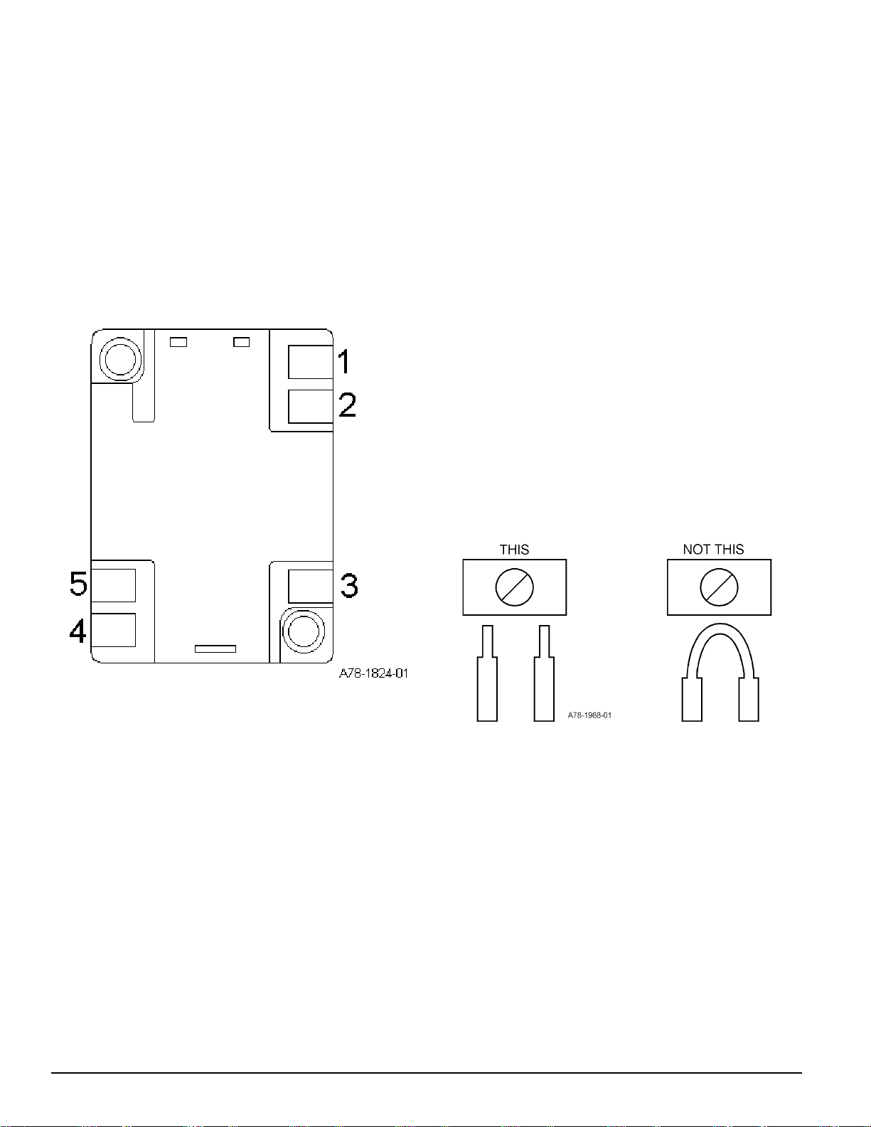
B401BH and B401BHA Terminals
No. Function
1 External Supply Positive (+)
2 External Supply Negative (–)
3 Negative (–) V in
4 Positive (+) V In and V Out
5 Negative (–) V Out
Terminals 3, 4, and 5 are used for the communication/initiating circuit.
Figure 1. Terminal Layout:
Installation Wiring Guidelines
All wiring must be installed in compliance with the National Electrical Code and all applicable local codes and
any special requirements of the authority having jurisdiction, using the proper wire size. The conductors used to
connect smoke detectors to control panels and accessory
devices should be color-coded to reduce the likelihood of
wiring errors. Improper connections can prevent a system
from responding properly in the event of a fire.
For signal wiring (the wiring between interconnected detectors), it is recommended that the wire be no smaller
than AWG 18. However, the screws and clamping plate in
the base can accommodate wire sizes up to AWG 12. The
use of twisted pair wiring or shielded cable for the power
(+ and –) loop is recommended to minimize the effects of
electrical interference on the initiating loop.
Begin electrical connections by stripping about 3/8" insulation from the end of the wire. Then, slide the bare end of
thewire under the clamping plate and tighten the clamping
plate screw. Break the wire at each terminal to ensure that
the connections are supervised, as shown in Figure 2.
Figure 2.
DO NOT loop the wire under the clamping plate.
Check the zone wiring of the detector base before the detector heads are installed. Perform continuity, base polarity,
and dielectric tests on the wiring.
Smoke detectors and alarm system control panels have
specifications for allowable supervision current. Consult
the control panel manufacturer’s specifications for the total
loop current supervision allowed for the control panel being used before wiring the detector loops.
D400-50-00 2 I56-612-03
Technical Manuals Online! - http://www.tech-man.com
Page 47
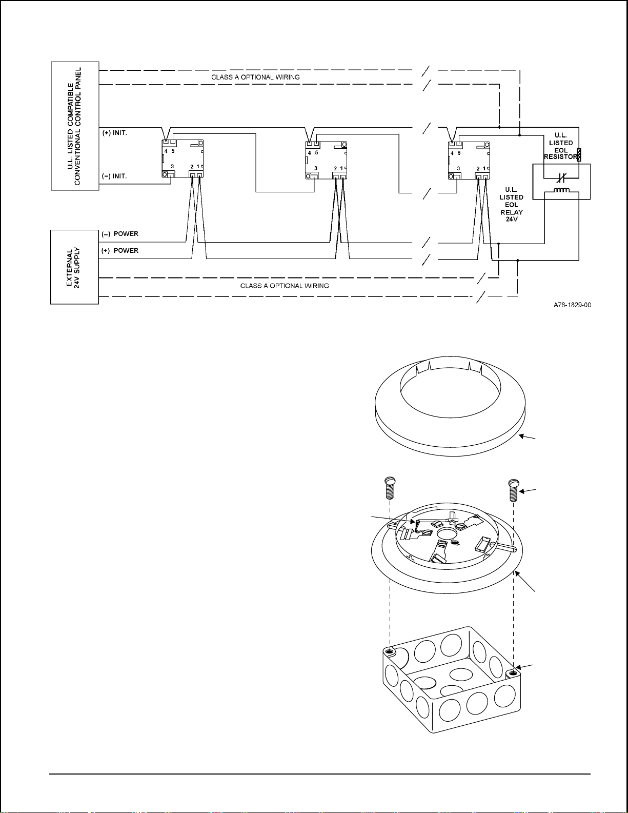
Figure 3. Typical wiring layout:
Wiring Instructions
The shorting spring in the base will disengage automatically when the detector head is removed from the base.
DO NOT remove the shorting spring since it reengages as
the detector head is turned into the base, completing the
circuit.
A typical wiring for a two-wire conventional system is
shown in Figure 3. Refer to this diagram as needed while
wiring the base into the system.
NOTE: Figure 3 shows external 24V supply polarity when
the loop system is in standby (NOT alarming).
Mounting
NOTE: It is recommended that the base be completely
wired before mounting.
See Figure 4. Attach the base directly to an electrical box
using the screws supplied with the box. Then, use the plastic screw covers, supplied with the base, to cover the
screws.
The sounder base is 1.1 inches (28 mm) deep. Electrical
boxes must be 4 inches (102 mm) square by at least 1-1/2
inches (38 mm) deep; 2-1/8 inches (54 mm) is recommended.
Figure 4. Mounting to an electrical box:
SHORTING
SPRING
SNAP ON
DECORATIVE
RING
SCREWS (NOT
SUPPLIED)
DETECTOR
BASE
BOX (NOT
SUPPLIED)
D400-50-00 3 I56-612-03
Technical Manuals Online! - http://www.tech-man.com
A78-1175-01
Page 48

Testing
Before testing, notify the proper authorities that the smoke
detector system is undergoing maintenance and that the
system will be temporarily out of service. Disable the zone
or system undergoing maintenance to prevent unwanted
alarms.
Detectors and bases must be tested after installation and
following periodic maintenance.
The Limitations of Property Protection Smoke Detectors
The sounder in this base will not operate if the power is cut off for any
reason.
The sounder may not be heard. The loudness of the sounder meets or
exceeds the current standards. However, the sounder may not alert a
sound sleeper or one who has recently used drugs or has been drinking
alcoholic beverages. This sounder may not be heard if it is placed in an
area which is separated by a closed door, or if it is located on a different
floor from the person in a hazardous situation, or if it is placed too far
away to be heard over the ambient noise such as traffic, air conditioners,
machinery, or musical appliances that may prevent alert persons from
hearing the alarm.
The sounder may not be heard by persons who are hearing impaired.
In this case, a visual indicator shall also be used.
Test the B401BH/B401BHA as follows:
1. Test the conventional detector head following the procedure in its manual. The B401BH/B401BHA should sound
approximately 10 seconds after the detector alarms.
2. Reverse the polarity of the external 24 VDC supply. This
should cause every base in the loop to sound after approximately 10 seconds.
WARNING
closed door may not reach the smoke detector and alarm it. A detector
cannot quickly detect, or sense at all, a fire developing on another level of
a building. For this reason, detectors shall be located on every level and
in every bedroom within a building.
Smoke detectors have sensing limitations, too. Ionization detectors and
photoelectronic detectors are required to pass fire tests of the flaming and
smoldering types. This is to ensure that both can detect a wide range of
fires. Ionization detectors offer a broad range of fire-sensing capability, but
they are somewhat better at detecting fast-flaming fires than slow-smoldering fires. Photoelectronic detectors sense smoldering fires better than
flaming fires, which have little, if any, visible smoke. Because fires develop
in different ways, and are often unpredictable in their growth, neither type
of detector is always best, and a given detector may not always provide
early warning of a specific type of fire.
This smoke detector used with this base is designed to activate and ini-
tiate emergency action, but will do so only when used in conjunction with
an authorized fire alarm system. This detector must be installed in accordance with NFPA standard 72.
Smoke detectors will not work without power. AC or DC powered
smoke detectors will not work if the power supply is cut off .
Smoke detectors will not sense fires which start where smoke does not
reach the detectors. Smoldering fires typically do not generate a lot of
heat which is needed to drive smoke up to the ceiling where the smoke
detector is usually located. For this reason, there may be large delays in
detecting a smoldering fire with either an ionization-type detector or a
photoelectronic-type detector. Either one of them may alarm only after
flaming has initiated, which will generate the heat needed to drive the
smoke to the ceiling.
Smoke from fires in chimneys, in walls, on roofs, or on the other side of a
Three-Year Limited Warranty
System Sensor warrants its enclosed base to be free from defects in materials and workmanship under normal use and service for a period of three
years from date of manufacture. System Sensor makes no other express
warranty for this base. No agent, representative, dealer, or employee of the
Company has the authority to increase or alter the obligations or limitations of this Warranty. The Company’s obligation of this Warranty shall be
limited to the repair or replacement of any part of the base which is found
to be defective in materials or workmanship under normal use and service
during the three year period commencing with the date of manufacture.
After phoning System Sensor’s toll free number 800-SENSOR2 (736-7672)
for a Return Authorization number, send defective units postage prepaid
to: System Sensor, Repair Department, RA #__________, 3825 Ohio Av-
In general, detectors cannot be expected to provide warnings for fires resulting from inadequate fire protection practices, violent explosions, escaping gases that ignite, improper storage of flammable liquids like
cleaning solvents that ignite, other similar safety hazards, arson, smoking
in bed, children playing with matches or lighters, etc. Smoke detectors
used in high air velocity conditions may have a delay in alarm due to dilution of smoke densities created by frequent and rapid air exchanges. Additionally, high air velocity environments may create increased dust
contamination, demanding more frequent detector maintenance.
Smoke detectors cannot last forever. Smoke detectors contain electronic
parts. Even though detectors are made to last over 10 years, any part can
fail at any time. Therefore, smoke detectors shall be replaced after being in
service for 10 years. The smoke detector system that this detector is used
in must be tested regularly per NFPA 72. This smoke detector should be
cleaned regularly per NFPA 72 or at least once a year.
enue, St. Charles, IL 60174. Please include a note describing the malfunction and suspected cause of failure. The Company shall not be obligated to
repair or replace units which are found to be defective because of damage,
unreasonable use, modifications, or alterations occurring after the date of
manufacture. In no case shall the Company be liable for any consequential
or incidental damages for breach of this or any other Warranty, expressed
or implied whatsoever, even if the loss or damage is caused by the
Company’s negligence or fault. Some states do not allow the exclusion or
limitation of incidental or consequential damages, so the above limitation
or exclusion may not apply to you. This Warranty gives you specific legal
rights, and you may also have other rights which vary from state to state.
D400-50-00 4 I56-612-03
Technical Manuals Online! - http://www.tech-man.com
© System Sensor 1996
Page 49

INSTALLATION AND MAINTENANCE INSTRUCTIONS
B401BR750 Plug-in Detector Base
For use with the following smoke detectors:
1451, 2451, and 2451TH
Specifications
Base Diameter: 6.2 inches (157 mm)
Base Height: 1.1 inches (29 mm)
Weight: 0.3 lb. (130 g)
Mounting: 4-inch square box with or without plaster ring. Min. Depth–1.5 inches
4-inch octagon box. Min. Depth–1.5 inches
3-1/2 inch octagon box. Min. Depth–1.5 inches
Operating Temperature Range: 0° to +49°C (32° to 120°F)
Operating Humidity Range: 10% to 93% Relative Humidity, noncondensing
Electrical Ratings — includes base and detector
System Voltage: 12/24 VDC
Maximum Ripple Voltage: 4 Volts peak to peak
Start-up Capacitance: 0.02 µF Maximum
Standby Ratings: 17 VDC Minimum; 32 VDC Maximum
120 µA Maximum
Alarm Ratings: 10mA Minimum at 13.5 VDC; 39mA Maximum at 32 VDC
(If used, the RA400 remote lamp operates within specified detector alarm currents.)
Reset Voltage: 2.5 VDC Minimum
Reset Time: 0.3 Seconds Maximum
Start-up Time: 34.0 Seconds Maximum
3825 Ohio Avenue, St. Charles, Illinois 60174
1-800-SENSOR2, FAX: 630-377-6495
A Division of Pittway
Before Installing
Please thoroughly read the System Sensor manual I56-407,
Guide for Proper Use of System Smoke Detectors, which
provides detailed information on detector spacing, placement, zoning, wiring, and special applications. Copies of
this manual are available at no charge from System Sensor.
(For installations in Canada, refer to CAN4-S524, Standard
for the Installation of Fire Alarm Systems, and CEC Part 1,
Sec. 32.)
NOTICE: This manual should be left with the owner/user
of this equipment.
IMPORTANT: The detector used with this base must be
tested and maintained regularly following NFPA 72 requirements. The detector used with this base should be cleaned
at least once a year.
General Description
The B401BR750 plug-in detector base is used with System
Sensor model 2451 and 2451TH photoelectronic detector
heads and model 1451A ionization detector heads. The capability of plugging these detectors into a variety of special
bases makes them more versatile than equivalent directwired models. Refer to the System Sensor catalog for other
available plug-in detector bases.
This base is intended for use in 2-wire systems, with screw
terminals provided for power, ground, and remote annunciator connections. It also contains a resistor to provide
current limiting in the alarm state.
D450-09-00 1 I56-451-02
Technical Manuals Online! - http://www.tech-man.com
Page 50

Mounting
This detector base mounts directly to 3-1/2-inch and 4-inch
octagon boxes, and 4-inch square boxes (with or without
plaster rings). To mount, remove the decorative ring by
turning it in either direction to unhook the snaps, then
separate the ring from the base.
Install the base to the box using the screws supplied with
the junction box and the appropriate mounting slots in the
base (see Figure 1). Place decorative ring onto base, then
turn in either direction until the ring snaps in place.
Installation Guidelines
All wiring must be installed in compliance with the National Electrical Code and the local codes having jurisdiction. Proper wire gauges should be used. The conductors
used to connect smoke detectors to control panels and accessory devices should be color-coded to reduce the likelihood of wiring errors. Improper connections can prevent a
system from responding properly in the event of a fire.
Figure 1. Mounting base to box:
SHORTING
SPRING
SNAP ON
DECORATIVE
RING
SCREWS (NOT
SUPPLIED)
DETECTOR
BASE
For signal wiring (the wiring between interconnected detectors), it is recommended that the wire be no smaller
than 18 gauge (1.0 square mm). Wire sizes up to 12 gauge
wire (2.5 square mm) may be used with the base. For best
system performance, the power (+) and (–) loop wires
should be twisted pair and installed in separate grounded
conduit to protect the loop from extraneous electrical interference.
Smoke detectors and alarm system control panels have
specifications for allowable loop resistance. Consult the
control panel manufacturer’s specifications for the total
loop resistance allowed for the particular model control
panel being used before wiring the detector loops.
Locate installations where the normal ambient temperatures do not exceed 100° F.
BOX (NOT
SUPPLIED)
A78-1175-01
D450-09-00 2 I56-451-02
Technical Manuals Online! - http://www.tech-man.com
Page 51

Wiring Instructions
leads and permits the wiring of the loop to be checked for
continuity.
CAUTION
For system supervision — For terminals 2, 3, and 5 do not
use looped wire under terminals. Break wire run to provide
system supervision of connections.
Wire connections are made by simply stripping insulation
from the end of the wire, sliding the bare end of the wire
under the clamping plate, and tightening the clamping
plate screw. Use the strip gauge molded into the base for
ease of wiring to terminals 1 through 5.
System Sensor smoke detectors and mounting bases are
marked with a compatibility identifier located as the last
digit of a five digit code stamped on the back of the product. Connect detectors/mounting bases only to compatible
control units as indicated in System Sensor’s compatibility
chart which contains a current list of UL listed control units
and detector head/base combinations. A copy of this list is
available from System Sensor upon request.
The zone wiring of the detector base should be checked
before the detector heads are installed in them. To make
this possible, this base contains a special spring-type shorting jumper. After a detector base is properly wired and
mounted on an electrical box, make sure that the jumper
spring is in contact with the base of Terminal 3. This temporary connection shorts the negative-in and negative-out
Once all the detector bases have been wired and mounted,
and the loop wiring has been checked, the detector heads
may be installed in the bases. The shorting spring in the
base will disengage automatically when the detector head
is removed from the base. DO NOT remove the shorting
spring since it reengages as the detector head is turned into
the base, completing the circuit.
Tamper-resistance Feature
CAUTION
Do not use the tamper-resistance feature if the XR5 removal
tool is to be used.
The tamper-resistant tab, in the detector mounting bracket,
can make the detector tamper-resistant by making it necessary to use a small screwdriver or similar tool to detach the
detector from the bracket.
To make the detector tamper-resistant, use needle-nose pliers to break the smaller tab at the scribed line on the
tamper- resistance tab. Figure 3A (on page 4) shows the location of this tab on the detector mounting bracket. To remove a detector from the bracket after it has been made
tamper resistant, use a small screwdriver or other similar
tool, to depress the tamper-resistance tab in the slot on the
Figure 2. Typical wiring diagram for 2-wire detector systems:
–
2
–
+
REMOTE
ANNUNCIATOR
2-WIRE CONTROL PANEL
1
3
4
5
–
+
REMOTE
ANNUNCIATOR
+
CLASS A OPTIONAL WIRING
D450-09-00 3 I56-451-02
Technical Manuals Online! - http://www.tech-man.com
NOTE: IF REMOTE ANNUNCIATOR
IS NOT USED, POLARITY TO
THESE TERMINALS MAY BE
2
1
3
4
5
E
O
L
REVERSED.
A78-1175-05
Page 52

mounting bracket, and rotate the detector counterclockwise
(see Figure 3B).
The tamper-resistance feature can be defeated by breaking
and removing the plastic lever from the base. However, this
prevents ever using the feature again.
NOTE: The decorative ring must be removed before the
smoke detector can be detached from the base after the tamper-resistant capability is enabled.
Figure 3A. Activating the tamper-resistance feature: Figure 3B. Removing detector head from base:
BREAK TAB AT
PLASTIC LEVER
The smoke detector used with this base is designed to activate and initiate emergency action, but will do so only when it is used in conjunction
with an authorized fire alarm system. This detector must be installed in
accordance with NFPA standard 72.
Smoke detectors will not work without power. AC or DC powered
smoke detectors will not work if the power supply is cut off.
Smoke detectors will not sense fires which start where smoke does not
reach the detectors. Smoldering fires typically do not generate a lot of
heat which is needed to drive the smoke up to the ceiling where the
smoke detector is usually located. For this reason, there may be large delays in detecting a smoldering fire with either an ionization type detector
or a photoelectric type detector. Either one of them may alarm only after
flaming has initiated which will generate the heat needed to drive the
smoke to the ceiling.
Smoke from fires in chimneys, in walls, on roofs or on the other side of a
closed door(s) may not reach the smoke detector and alarm it. A detector
cannot detect a fire developing on another level of a building quickly or at
all. For these reasons, detectors shall be located on every level and in
every bedroom within a building.
Smoke detectors have sensing limitations, too. Ionization detectors and
photoelectric detectors are required to pass fire tests of the flaming and
DOTTED LINE BY
TWISTING TOWARD
CENTER OF BASE.
The Limitations of Property Protection Smoke Detectors
USE SMALL-BLADED
SCREWDRIVER TO
PUSH PLASTIC LEVER
IN DIRECTION OF
ARROW.
WARNING
smoldering type. This is to ensure that both can detect a wide range of
types of fires. Ionization detectors offer a broad range of fire sensing capability but they are somewhat better at detecting fast flaming fires than
slow smoldering fires. Photoelectric detectors sense smoldering fires better
than flaming fires which have little, if any, visible smoke. Because fires develop in different ways and are often unpredictable in their growth, neither type of detector is always best, and a given detector may not always
provide early warning of a specific type of fire.
In general, detectors cannot be expected to provide warnings for fires resulting from inadequate fire protection practices, violent explosions, escaping gases which ignite, improper storage of flammable liquids like
cleaning solvents which ignite, other similar safety hazards, arson, smoking in bed, children playing with matches or lighters, etc. Smoke detectors
used in high air velocity conditions may have a delay in alarm due to dilution of smoke densities created by frequent and rapid air exchanges. Additionally, high air velocity environments may create increased dust
contamination, demanding more frequent maintenance.
Smoke detectors cannot last forever. Smoke detectors contain electronic
parts. Even though smoke detectors are made to last over 10 years, any
part can fail at any time. Therefore, smoke detectors shall be replaced after
being in service for 10 years. The smoke detector system that this detector
is used in must be tested regularly per NFPA 72. This smoke detector
should be cleaned regularly per NFPA 72 or at least once a year.
A78-1175-03
Three-Year Limited Warranty
System Sensor warrants its enclosed smoke detector base to be free from
defects in materials and workmanship under normal use and service for a
period of three years from date of manufacture. System Sensor makes no
other express warranty for this smoke detector base. No agent, representative, dealer, or employee of the Company has the authority to increase or
alter the obligations or limitations of this Warranty. The Company’s obligation of this Warranty shall be limited to the repair or replacement of any
part of the smoke detector base which is found to be defective in materials
or workmanship under normal use and service during the three year period commencing with the date of manufacture. After phoning System
Sensor’s toll free number 800-SENSOR2 (736-7672) for a Return Authorization number, send defective units postage prepaid to: System Sensor,
D450-09-00 4 I56-451-02
Technical Manuals Online! - http://www.tech-man.com
Repair Department, RA #__________, 3825 Ohio Avenue, St. Charles, IL
60174. Please include a note describing the malfunction and suspected
cause of failure. The Company shall not be obligated to repair or replace
units which are found to be defective because of damage, unreasonable
use, modifications, or alterations occurring after the date of manufacture.
In no case shall the Company be liable for any consequential or incidental
damages for breach of this or any other Warranty, expressed or implied
whatsoever, even if the loss or damage is caused by the Company’s negligence or fault. Some states do not allow the exclusion or limitation of incidental or consequential damages, so the above limitation or exclusion may
not apply to you. This Warranty gives you specific legal rights, and you
may also have other rights which vary from state to state.
© System Sensor 1996
 Loading...