

Page 1
V+ V+
4351E
5351E
5351TE
57mm
B401x
70°C
-30°C
*4351E ALARM
THRESHOLD IS 78°C
105 g
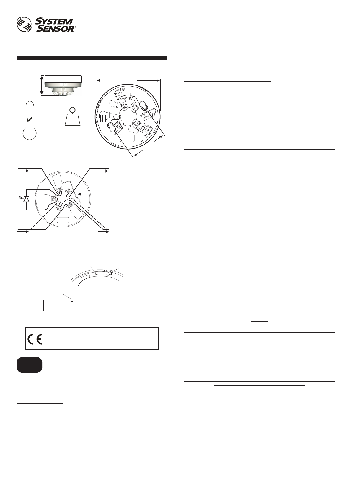
Figure 1: Base Terminal Wiring
V- V-
2
3
1
+
5
Figure 2: Tamper Resist Feature
TO REMOVE, USE A SMALL
SCREWDRIVER TO PUSH
PLASTIC IN THE DIRECTION
OF THE ARROW, WHILST
ROTATING THE SENSOR
ANTI-CLOCKWISE
0832 05
4
R
PLASTIC LEVER
Declaration of Performance Ref:
4351E: 0832-CPD-0061
5351E: 0832-CPD-0062
5351TE: 0832-CPD-0063
SHORTING SPRING
NOTE: WHEN A BASE FITTED WITH A
RESISTOR (R) - BETWEEN TERMINALS
4 AND 5 - IS USED, THE WIRING SHOULD
FOLLOW THE DASHED LINE.
TO ACTIVATE, BREAK TAB ON PLASTIC
LEVER AT DOTTED LINE BY TWISTING
TOWARD CENTRE OF BASE
ENGLISH
INSTALLATION AND MAINTENANCE INSTRUCTIONS
4351E 78°C FIXED TEMPERATURE
5351E 58°C plus RATE OF RISE
GENERAL DESCRIPTION
Model 4351E, 5351E and 5351TE heat detectors use a single thermistor sensing element
combined with state of the art electronics to provide ambient temperature compensation
and fast response. The ability to plug these sensors into a variety of base options extends
panel compatibility and application exibility. These sensors are designed to provide
open area protection and are only to be used with compatible control panels.
A bicolour LED on each sensor lights red to provide a local visible alarm indication, ashes
yellow to indicate a chamber fault or drift compensation limit reached, and may also be
set to ash green to indicate correct operation of the sensor. Remote LED annunciator
capability is available as an optional accessory wired to the standard base terminals.
These sensors also have a latching alarm feature. The alarm can be reset only by a
momentary power interruption.
A dedicated tool is available from System Sensor, which may be used to access operating
data from the sensor.
5351TE 58°C FIXED TEMPERATURE
102 mm
60 mm
A SCHOTTKY DIODE
CONNECTED BETWEEN
TERMINALS 2 AND 3 DOES
NOT AFFECT BASE WIRING.
Pittway Tecnologica
S.r.l,
Via Caboto 19/3,
34147 Trieste, Italy
SPECIFICATIONS
Supply voltage 8 - 30VDC
Air velocity 20m/s (4000 ft/min)
Humidity 5 - 95%RH (non-condensing)
Quiescent current 60µA Typical (4351E 65μA)
Maximum alarm current 80mA (Limited by panel or base resistance)
Latching alarm Reset by momentary power interruption.
The 5351E has been independently tested and certied to EN54-5 Class A1R.
The 5351TE has been independantly tested and certied to EN54-5 Class A2S.
The 4351E has been independently tested and certied to EN54-5 Class BS.
Note: Do not install in locations where the normal ambient temperature range extends
beyond 0°C to 50°C for extended periods.
BASE MOUNTING AND WIRING INSTRUCTIONS
Verify that the sensor base supplied is compatible with the system control panel.
400 series bases may be mounted to standard electrical junction boxes with 50-60 mm
centre xings.
See gure 1 for terminal connections on standard bases. If relay bases are to be used,
please refer to the relevant base instructions.
Notes:
1. Series 300 sensors are polarity conscious, and must be wired as indicated.
2. Do not loop wire under terminals: break the wire run to ensure supervision of
connections.
3. All wiring must conform to applicable local and national codes and regulations.
Each 400 series base is tted with a shorting spring, which may be used to connect across
terminals 2 and 3 to permit loop wiring to be checked before installation of sensor heads.
This spring automatically disengages when the sensor is tted into the base.
Remove power from sensor monitoring circuits before installing sensors.
SENSOR INSTALLATION
1. Insert the sensor into the base and rotate it clockwise until it locks into place.
2. After all sensors have been installed, apply power to the sensor monitoring circuits.
3. Test the sensor as described under TESTING.
4. Reset the sensor at the system control panel.
Tamper-resistance
The sensor bases include a feature that, when activated, prevents removal of the sensor
without the use of a tool. See gure 2 for details.
Dust covers are tted to the sensors to help protect units during shipment and
when rst installed. They are not intended to provide complete protection
against contamination; therefore sensors should be removed before beginning
construction, major re-decoration or other dust producing activity. Dust covers
must be removed before the system can be made operational.
TESTING
Sensors must be tested after installation and following periodic maintenance. Disable the
zone or system undergoing maintenance to prevent unwanted alarms. Test the sensor
as follows:
Direct Heat method
1. Use either a specialised tool such as supplied by No Climb Products Limited, or a
hairdryer of 1000 to 1500 Watts.
2. Direct the heat towards the sensor thermistor from it’s side. Hold the heat source
about 15cm away from the detector to prevent damage during the test.
3. The red LED on the detector should latch into alarm within 40 seconds, and the
control panel should activate into alarm.
Laser test tool method (model no. S300RTU)
Note: this method does not carry out a complete functional test of the sensor.
1. Align the ashing red spot produced by the laser beam with the LED on the sensor.
2. The red LED on the sensor should latch into alarm within a few seconds, and the
control panel should activate into alarm.
The S300RTU test tool is a Class II laser product. Do not direct the beam towards
After completion of all tests notify the proper authorities that the re system is operational.
MAINTENANCE
Before cleaning, disable the system to prevent unwanted alarms.
1. Remove the sensor to be cleaned from the system.
2. Use a vacuum cleaner and/or clean, compressed air to remove dust and debris from
the thermistor and sensor cover.
3. Replace the sensor into the base
4. When all the sensors have been cleaned, restore power to the circuit and test the
sensor as described in TESTING above.
WARNING - LIMITATIONS OF THERMAL SENSORS
Fire sensors must be used in conjunction with compatible equipment.
Heat sensors are designed to protect property, not life. They do not provide early
warning of re and cannot detect smoke, gas, combustion particles or ame.
Heat sensors do not always detect res because the re may be a slow smouldering,
low-heat type (producing smoke) or because they may not be near where the re occurs,
or because the heat of the re may bypass them. Consideration must be made of the
environment when selecting heat sensors.
Fire sensors cannot last forever. Fire sensors contain electronic parts. Even though
sensors are made to last over 10 years, any of these parts could fail at any time.
Therefore, test your re detection system at least semi-annually. Taking care of the re
detection system you have installed will signicantly reduce your product liability risks.
WARNING
CAUTION
CAUTION
a person’s face or eyes
D300-02-01 I56-1719-020
Pittway Tecnologica S.r.l. Via Caboto 19/3, 34147 TRIESTE, Italy
Page 2

V+ V+
4351E
5351E
5351TE
57mm
B401x
70°C
-30°C
*LA SOGLIA DI ALLARME È
78°C PER IL 4351E
Figura1: Cablaggio ai terminali della base
105 g
V- V-
2
3
1
+
5
R
Figura 2: Anti-manomissione
LEVA DI PLASTICA
PER RIMUOVERE UN
RIVELATORE, IUTILIZZARE UN
PICCOLO CACCIAVITE A LAMA
PIATTA PER SPINGERE LA
PLASTICA NELLA DIREZIONE
DELLA FRECCIA
0832 05
4
Declaration of Performance Ref:
4351E: 0832-CPD-0061
5351E: 0832-CPD-0062
5351TE: 0832-CPD-0063
MOLLA DI CORTOCIRCUITO
NOTA: QUANDO SI UTILIZZA UNA BASE
CON UN RESISTORE TRA I TERMINALI 4 E
5, IL CABLAGGIO DOVREBBE SEGUIRE LE
INDICAZIONI TRATTEGGIATE.
PER ATTIVARE IL DISPOSITIVO DI
ANTI-MANOMISSIONE, ROMPERE LA
LINGUETTA LUNGO LA LINEA
TRATTEGGIATA RUOTANDOLA VERSO
IL CENTRO DELLA BASE
ITALIANO
ISTRUZIONI DI INSTALLAZIONE E MANUTENZIONE
4351E - 78°C ALTA TEMPERATURA FISSA
5351E - 58°C TERMOVELOCIMETRICO
DESCRIZIONE GENERALE
I rivelatori d’incendio termici 4351E, 5351E e 5351TE sono dotati di una camera di misura a singolo
termistore combinata ad una sosticata elettronica di controllo che provvede alla compensazione
della temperatura ambiente e risposta rapida. Una varietà di basi adattatrici estende la compatibilità
con le centrali di controllo e permette molteplici applicazioni in campo. Questo sensore è progettato
per l’utilizzo in ambienti aperti ed devono essere utilizzati solamente con centrali di contollo
compatibili.
Ogni rivelatore è dotato di un LED bicolore che indica l’allarme quando acceso in colore rosso è
giallo lampeggiante per indicare lo stato di fault della camera o per avvisare del raggiungimento del
limite della compensazione del drift e, se il rivelatore viene impostato opportunamente, il corretto
funzionamento dell’unità mediante lampeggio a luce verde. Un ulteriore LED, detto avvisatore
remoto, può essere collegato al sensore utilizzando gli opportuni terminali presenti sulla base di
montaggio. La condizione di allarme viene mantenuta nel tempo è può essere terminata solamente
con una rimozione, temporanea, dell’alimentazione.
Uno strumento dedicato, disponibile presso System Sensor, può essere usato per accedere ai dati
operativi del rivelatore.
5351TE - 58°C TEMPERATURA FISSA
102 mm
60 mm
UN DIODO SCHOTTKY TRA I
TERMINALI 2 E 3 NON ALTERA
IL CABLAGGIO DELLA BASE.
Pittway Tecnologica
S.r.l,
Via Caboto 19/3,
34147 Trieste, Italy
DATI TECNICI
Tensione di alimentazione: 8 - 30VDC
Velocità dell’aria: 20m/s (4000ft/min)
Campo umidità ambiente: 5 - 95%UR (condizionato all’assenza di condensa)
Corrente di riposo: 60µA (4351E 65µA)
Massim a corre nte d’a llarme 80mA (Limitata dalla centrale o dalla resistenza presente nella base)
Condizione di allarme: Terminabile mediante temporanea interruzione dell’alimentazione.
Il 4351E è stato testato indipendentemente ed approvato secondo EN54 parte 5, classe BS.
Il 5351E è stato testato indipendentemente ed approvato secondo EN54 parte 5, classe A1R.
Il 5351TE è stato testato indipendentemente ed approvato secondo EN54 parte 5, classe A2S.
Note: Non installare in luoghi dove la temperatura normalmente è inferiore a 0°C o superiore a
50°C.
MONTAGGIO DELLA BASE E COLLEGAMENTO AL CABLAGGIO
Vericare che la base acquistata sia compatibile con la centrale di controllo del sistema.
Basi della serie 400 possono essere montate su scatole di derivazione con centri di ssaggio a 50
oppure 60mm di interasse. Vedere le gura 1 per i collegamenti elettrici.
Note:
1. I rivelatori della 300 sono polarizzati, devono essere collegati come indicato.
2. Interrompere sempre le linee sui morsetti per permettere la corretta supervisione del cablaggio.
3. Il cablaggio deve rispondere ai requisiti dei regolamenti e delle norme nazionali.
Ogni base della serie 400è dotata di una molla di cortocircuito che può essere utilizzata per collegare i
terminali 2 e 3 permettendo così di vericare l’integrità del cablaggio prima di procedere al montaggio
dei rivelatori. Questa molla recupera la posizione di riposo automaticamente all’innesto di un sensore.
INSTALLAZIONE DEL RIVELATORE
1. Posizionare il rivelatore nella base e ruotare in senso orario esercitando una moderata
2. Continuare la rotazione no ad avvertire il blocco.
3. Quando tutti i rivelatori sono stati inseriti, alimentare il sistema.
4. Vericare i rivelatori come descritto nella sezione VERIFICA.
5. Re-inizializzare i rivelatori utilizzando la relativa funzione della centrale di controllo.
Anti-manomissione
Le basi dei rivelatori includono una caratteristica che, quando attivata, previene la rimozione del
rivelatore. Essa rimane ovviamente possibile ma soltanto attraverso un utensile. Vedere gura 2 per
i dettagli.
Ai rivelatori è applicato un parapolvere che previene possibili danneggiamenti causati dal
trasporto e limita l’ingresso nel rivelatore della polvere che si può creare nel momento
dell’installazione. Questa protezione è ad ogni modo limitata; i rivelatori dovrebbero
essere rimossi prima di iniziare interventi di ristrutturazione, costruzione od altre attività
similari che possano produrre notevoli quantità di polvere. Il parapolvere deve essere
VERIFICA
I rivelatori devono essere testati successivamente all’installazione od alla manutenzione. Per
prevenire allarmi indesiderati, disabilitare le segnalazioni di incendio alle zone che saranno vericate
oppure al sistema intero, in accordo a quanto specicato nel manuale d’uso della centrale di controllo.
Vericare il rivelatore come segue:
Risposta al calore, riscaldamento diretto
1. IUsare un apparecchiatura dedicata (No Climb Products Ltd od equivalenti) oppure un
2. Indirizzare il getto d’aria calda lateralmente al rivelatore, in modo che possa attraversare lo
3. Il LED rosso sul rivelatore deve accendersi entro 40 secondi e la centrale di controllo deve
Telecomando laser (Accessorio codice S300RTU)
Nota: Questo test non verica completamente la funzionalità del rivelatore.
1. Allineare il fascio laser (punto lampeggiante rosso) prodotto dall’accessorio al LED del
2. Il LED rosso sul rivelatore deve accendersi entro pochi secondi e la centrale di controllo deve
Lo strumento di test S300RTU contiene un laser di Classe II. Non puntare il fascio verso
Conclusi tutti i test, riattivare il sistema e noticarne la messa in funzione.
MANUTENZIONE
Per prevenire allarmi indesiderati, disabilitare le segnalazioni di incendio alle zone che saranno
vericate oppure al sistema intero, in accordo a quanto specicato nel manuale d’uso della centrale
di controllo.
1. Rimuovere dalla sua base il rivelatore da pulire.
2. Utilizzare un aspirapolvere e/o un dispositivo ad aria compressa pulita per rimuovere la polvere
3. Rimontare il sensore sulla base.
4. Una volta puliti tutti i sensori, alimentare il sistema e testare i rivelatori come descritto nella
I sensori di incendio devono essere utilizzati in combinazione con apparecchiature compatibili.
I sensori di calore sono stati concepiti per proteggere la proprietà, non la vita. Non
garantiscono una rilevazione tempestiva di incendi e non sono in grado di rilevare fumo, gas, particelle
di combustione o amme.
I sensori di calore non sempre rilevano gli incendi in quanto l’incendio può essere del tipo senza amma,
o del tipo con scarsa produzione di calore (formazione di fumo), in quanto potrebbero non trovarsi in
prossimità del punto d’innesco dell’incendio o in quanto il calore dell’incendio li ha bypassati. Al momento
della scelta dei sensori di calore occorre tenere in considerazione l’ambiente in cui verranno installati.
I sensori di incendio non durano in eterno. I sensori di incendio contengono componenti elettronici.
Sebbene i sensori siano stati progettati per durare oltre 10 anni, un qualsiasi loro componente potrebbe
smettere di funzionare in qualsiasi momento. Pertanto si consiglia la revisione del sistema di rilevazione
di incendio almeno ogni sei mesi. La corretta manutenzione del sistema di rilevazione di incendio
installato riduce signicativamente i rischi di responsabilità..
Togliere alimentazione al sistema prima di installare i sensori.
pressione no a quando il rivelatore raggiunge la sua posizione.
rimosso prima di rendere operativo il sistema di rivelazione d’incendio.
asciugacapelli da 1000-1500W.
stesso attraverso le feritoie predisposte sull’involucro esterno.
indicare la condizione di allarme.
rivelatore.
indicare la condizione di allarme.
e lo sporco dal termistore e dal coperchio del sensore.
sezione VERIFICA.
LIMITAZIONI DEI RIVELATORI DI CALORE
ATTENZIONE
CAUTELA
CAUTELA
il viso o gli occhi delle persone.
ATTENZIONE
D300-02-01 I56-1719-020
Pittway Tecnologica S.r.l. Via Caboto 19/3, 34147 TRIESTE, Italy
Page 3

V+ V+
4351E
5351E
5351TE
57mm
B401x
70°C
-30°C
*CEL UMBRAL DE ALARMA
DE 4351E ES 78ºC
Figura 1: Cableado de los Terminales de la Base
V- V-
1
+
Figura 2: Opción de seguridad antimanipulaciones
PARA RETIRAR UN DETECTOR
UNA VEZ ACTIVADA LA OPCIÓN
ANTIMANIPULACIONES,
UTILICE UN DESTORNILLADOR
PEQUEÑO PARA EMPUJAR LA
PESTAÑA DE PLÁSTICO EN LA
DIRECCIÓN DE LA FLECHA.
0832 05
ESPAÑOL
INSTRUCCIONES DE INSTALACIÓN Y MANTENIMIENTO
5351E - TEMPERATURA FIJA A 58 ºC Y TERMOVELOCIMÉTRICOS
DESCRIPCIÓN GENERAL
Los detectores de temperatura modelo 4351E, 5351E y 5351TE utilizan un único termistor como
elemento de detección combinado con circuitería electrónica de última generación para proporcionar
compensación de la temperatura ambiente y una rápida respuesta. La capacidad de conectar estos
detectores a diversas opciones de base amplía la compatibilidad con paneles y la exibilidad de
aplicación. Estos detectores han sido diseñados para proporcionar protección en zonas diáfanas y
sólo se pueden utilizar con paneles de control compatibles.
Un led bicolor en el detector se ilumina en rojo para indicar alarma, parpadea en amarillo para
indicar fallo de cámara o que se ha alcanzado el nivel máximo de compensación por suciedad, y
también se puede ajustar para que parpadee en verde para indicar que el detector está funcionando
correctamente. Se puede disponer de un LED indicador remoto como accesorio opcional conectado
a los terminales de base estándar. Estos detectores también poseen la función de enclavamiento
de alarma. Ésta sólo puede desactivarse mediante una interrupción momentánea del suministro
eléctrico.
System Sensor dispone de una herramienta especíca para acceder a los datos de funcionamiento
del detector.
105 g
2
3
PESTAÑA METÁLICA DE CONTINUIDAD
NOTA: CUANDO SE UTILIZA UNA BASE
4
5
R
Declaration of Performance Ref:
4351E: 0832-CPD-0061
5351E: 0832-CPD-0062
5351TE: 0832-CPD-0063
4351E - TEMPERATURA FIJA A 78 ºC
5351TE - TEMPERATURA FIJA A 58 ºC
CON RESISTENCIA (R) ENTRE LOS
TERMINALES 4 Y 5, EL CABLEADO A
SEGUIR ES EL DE LA LÍNEA DE PUNTOS
PESTAÑA DE
PLÁSTICO
102 mm
60 mm
LA CONEXIÓN DE UN
DIODO SCHOTTKY ENTRE
LOS TERMINALES 2 Y 3 NO
AFECTA AL CABLEADO DE
LA BASE.
PARA ACTIVAR LA OPCIÓN
ANTIMANIPULACIONES, ROMPA
LA PESTAÑA POR LA LÍNEA DE
PUNTOS GIRÁNDOLA HACIA EL
CENTRO DE LA BASE.
Pittway Tecnologica
S.r.l,
Via Caboto 19/3,
34147 Trieste, Italy
ESPECIFICACIONES
Tensión de Alimentación 8 - 30Vcc
Velocidad del Aire 20m/s (4000 pies/min)
Humedad 5 - 95%HR (sin condensación)
Corriente en reposo 60µA Típica (4351E 65µA)
Máxima corriente en alarma 80mA (limitada por la central o la resistencia, opcional,
Enclavamiento de la Alarma Rearmado mediante supresión momentánea de la tensión
El 5351E ha sido probado y certicado independientemente según EN54-5 Clase A1R.
El 5351TE ha sido probado y certicado independientemente según EN54-5 Clase A2S.
El 4351E ha sido probado y certicado independientemente según EN54-5 Clase BS.
Nota: No instalar en zonas en las que el margen de temperatura ambiente normal se extienda más
allá de 0°C a 50°C durante largos periodos de tiempo.
MONTAJE DE LA BASE E INSTRUCCIONES DE CABLEADO
Compruebe que la base suministrada con el detector es compatible con el panel de control del
sistema.
Las bases de la serie 400 se pueden montar en las cajas de conexiones eléctricas estándar por medio
de jaciones centrales de 50-60 mm.
Vea las conexiones de los terminales en la gura 1. Si se van a utilizar bases con relé, consulte las
instrucciones de la base en cuestión.
Notas:
1. Los detectores de la serie 300 tienen polaridad y se deben cablear según se indica.
2. No haga ramales con los cables comunes: Interrumpa el recorrido del hilo para asegurar la
supervisión de las conexiones.
3. Todo el conexionado deberá cumplir la normativa y reglamentos locales y nacionales aplicables.
Las bases de la serie 400 disponen de una pestaña metálica de continuidad que se puede utilizar
para conectar los terminales 2 y 3, permitiendo así la comprobación del cableado del lazo antes de
la instalación de las cabezas detectoras. Esta pestaña se desconecta automáticamente al acoplar el
detector en la base.
Desconecte la alimentación de la línea de los detectores antes de instalar éstos.
INSTALACIÓN DEL DETECTOR
1. Sitúe el detector en su base y gírelo en sentido horario ejerciendo una ligera presión, hasta que
éste quede en su lugar.
2. Una vez instalados los detectores conecte la alimentación de los circuitos de monitorización de
éstos.
3. Compruebe el detector según se describe en el apartado PRUEBAS.
4. Rearme el detector en el panel de control del sistema.
Opción de seguridad antimanipulaciones (bloqueo de extracción del detector)
La base del detector incluye una opción que, si se utiliza, impide que se extraiga el detector si no es
mediante el uso de una herramienta. Vea los detalles en la gura 2.
Los detectores se suministran con tapa para protegerlos del polvo durante el transporte
y etapa inicial de la instalación. No se pretende que estas tapas ofrezcan protección
total contra todo tipo de contaminación; por ello, antes de iniciarse cualquier trabajo de
construcción, decoración u otra actividad que genere polvo, los detectores deben ser
retirados. Extraiga esta protección antes de la puesta en marcha del sistema.
PRUEBAS
Los detectores han de comprobarse una vez instalados y durante los mantenimientos periódicos
posteriores. Anule el sistema para evitar alarmas no deseadas. Compruebe el detector como sigue:
Método de Calor Directo
1. Utilice una herramienta especializada, como la que suministra No Climb Products Ltd, o bien un
secador de pelo de 1000-1500 Vatios.
2. Dirija el calor lateralmente hacia el sensor . Mantenga la fuente de calor a una distancia de 15 cm
para evitar daños durante la comprobación.
3. El LED rojo del detector ha de encenderse y quedar enclavado en estado de alarma en los 40
segundos siguientes, activándose la alarma en el panel de control.
Método de Prueba con Láser (Modelo Núm. S300RTU)
Nota: Este método no lleva a cabo una comprobación funcional completa del detector.
1. Alinee el punto rojo producido por el rayo láser con el LED del detector.
2. El LED rojo del detector ha de encenderse y quedar enclavado en estado de alarma a los pocos
segundos, activándose la alarma en el panel de control..
El Láser S300RTU es un producto láser de Clase II. No dirija el haz a la cara u ojos de las
MANTENIMIENTO
Antes de limpiar los equipos avise al personal responsable que se está realizando el mantenimiento
del sistema y que éste permanecerá momentáneamente fuera de servicio. Anule el sistema para
evitar alarmas no deseadas.
1. Retire del sistema el detector que vaya a limpiar.
2. Utilice un aspirador o aire comprimido para eliminar el polvo y la suciedad del termistor y cubierta
del sensor.
3. Vuelva a colocar el sensor en la base.
4. Cuando termine de limpiar todos los detectores, conecte la alimentación al circuito y
compruébelos según se describe en el apartado PRUEBAS.
Los sensores de incendio deben utilizarse junto con equipamiento compatible.
Los sensores térmicos están diseñados para proteger los bienes materiales, no las
vidas. No proporcionan aviso incipiente del incendio y no pueden detectar humo, gas, partículas de
combustión o llamas.
Los sensores térmicos no siempre detectan los incendios porque puede que sea lento y genere poco
calor (produciendo humo) o que no se origine cerca de los sensores o bien los eluda. Para seleccionar
el sensor térmico adecuado, debe tener en cuenta el ambiente en el que se va a instalar.
Los sensores de incendio contienen piezas electrónicas y tienen una duración limitada.
Aunque los sensores tienen una vida útil de unos 10 años, alguna de las piezas electrónicas podría
fallar en cualquier momento. Por ello, el sistema de detección de incendios debe probarse, como
mínimo, cada seis meses. Un mantenimiento correcto del sistema de detección de incendio reducirá
signicativamente los riesgos en cuanto a su responsabilidad con el producto.
personas, podría causarles lesiones oculares
LIMITACIONES DE LOS DETECTORES TÉRMICOS
colocada en la base).
de alimentación.
AVISO
PRECAUCIÓN
PRECAUCIÓN
AVISO
D300-02-01 I56-1719-020
Pittway Tecnologica S.r.l. Via Caboto 19/3, 34147 TRIESTE, Italy
Page 4

V+ V+
4351E
5351E
5351TE
57mm
B401x
70°C
-30°C
*DIE ALARMSCHWELLE DES
TYP 4351E IST 78 °C
Abbildung 1: Verdrahtung des Meldersockels
V- V-
1
+
Abbildung 2: Sabotageschutz / Entnahmesicherung
ZUM ENTNEHMEN DES
MELDERS BEI AKTIVIERTER
ENTNAHMESICHERUNG,
NUTZEN SIE EINEN
SCHRAUBENDREHER
MIT SCHMALER KLINGE
UM DEN KUNSTSTOFF
IN PFEILRICHTUNG
HERAUSZUDRÜCKEN.
0832 05
DEUTSCH
ALLGEMEINE BESCHREIBUNG
Die Messkammer der Wärmemelder Typ 4351E, 5351E und 5351TE ist mit einem
Thermosensor nach dem modernsten Stand der Technik ausgerüstet, der eine Anpassung an
die Umgebungstemperatur und ein schnelles Ansprechverhalten gewährleistet. Die Möglichkeit
diesen Melder mit unterschiedlichen Meldersockeln einzusetzen erweitert den Einsatzbereich und
die Flexibilität des Brandmeldesystems. Dieser Melder wurde zur Brandfrüherkennung in Räumen
entwickelt und darf nur in Verbindung mit kompatiblen Brandmelderzentralen betrieben werden.
Die zweifarbige LED des Melders leuchtet rot auf wenn der Melder sich im Alarmzustand
bendet, blinkt gelb wenn eine Störung der Messkammer aufgetreten bzw. das Ende der
Messwertnachführung erreicht ist und blinkt grün im Normalbetrieb des Melders. Zusätzlich kann eine
optionale Parallelanzeige an den Meldersockel angeschlossen werden. Alle Brandmelder sind mit
einer Alarmspeicherung ausgerüstet, die durch kurzzeitige Unterbrechung der Betriebsspannung
wieder gelöscht werden kann.
Mit einem speziellen System Sensor Werkzeug kann auch auf die Betriebsdaten des Brandmelders
zugegriffen werden.
105 g
2
3
4
5
R
KUNSTSTOFFHEBEL
METALLFEDER
HINWEIS: MELDERSOCKEL MIT EINEM
WIDERSTAND ZWISCHEN DEN KLEMMEN 4
UND 5 SIND GEMÄSS DER GESTRICHELTEN
LINIE ZU VERDRAHTEN.
Declaration of Performance Ref:
4351E: 0832-CPD-0061
5351E: 0832-CPD-0062
5351TE: 0832-CPD-0063
Installations- und Wartungsanleitung
4351E HOHE ANSPRECHTEMPERATUR
5351E THERMODIFFERENTIAL
5351TE 58 GRAD ANSPRECHTEMPERATUR
102 mm
60 mm
EINE SCHOTTKY DIODE
ZWISCHEN DEN KLEMMEN 2
UND 3 HAT KEINEN EINFLUSS
AUF DIE VERDRAHTUNG
ZUM AKTIVIEREN DIE
SABOTAGESCHUTZ,
KUNSTSTOFFZUNGE AN
DER GEPUNKTETEN LINIE
DURCH EINE DREHUNG ZUR
INNENSEITE DES SOCKELS
ABTRENNEN
Pittway Tecnologica
S.r.l,
Via Caboto 19/3,
34147 Trieste, Italy
SPEZIFIKATION
Versorgungsspannung 8 - 30 VDC
Luftgeschwindigkeit 20m/s (4000ft/min)
Luftfeuchtigkeit 5-95% rel. (ohne Betauung)
Ruhestrom 60 µA, typisch (4351E 65µA)
Maximaler Alarmstrom 80 mA (begrenzt durch die BMZ oder den Widerstand im Sockel)
Alarmspeicherung Rücksetzbar durch kurzzeitige Unterbrechung der Betriebsspannung
Der Meldertyp 4351E wurde unabhängig geprüft gemäß der EN54-5 Klasse BS zertiziert.
Der Meldertyp 5351E wurde unabhängig geprüft gemäß der EN54-5 Klasse A1R zertiziert.
Der Meldertyp 5351TE wurde unabhängig geprüft gemäß der EN54-5 Klasse A2S zertiziert.
Hinweis: Installieren Sie den Melder nicht an Orten an denen der zulässige Betriebstemperatur-
bereich von 0°C bis 50 °C.
MONTAGE UND VERDRAHTUNG DES MELDERSOCKELS
Vergewissern Sie sich das der eingesetzte Meldersockel und die Brandmelderzentrale zueinander
kompatibel sind.
Die Meldersockel der Serie 400 können auf Standard Verteilerdosen mit den 50-60mm
Befestigungslöcher montiert werden.
Die Abbildung 1 zeigt die Klemmenbelegung der Standardsockel. Wenn Relaissockel eingesetzt
werden folgen Sie den Hinweisen der entsprechenden Installationsanleitung sowie dem
Verpackungsaufdruck.
Hinweise:
1. Polarität beachten, Melder der Serie 300 müssen gemäß der o.a. Abbildung verdrahtet werden.
2. Keine Kabelschlaufen unter die Klemmen legen. Zur besseren Übersicht sollte die
Kabelführung unterbrochen sein.
3. Die Verdrahtung muss gemäß den gültigen regionalen Richtlinien und gesetzlichen
Bestimmungen ausgeführt werden.
Um die Verdrahtung vor dem Einsetzen der Brandmelder überprüfen zu können, ist eine Metallfeder
zum Überbrücken der beiden Klemmen Nr. 2 und Nr.3 eingebaut. Die Überbrückung wird mit dem
Einsetzen des Brandmelders automatisch wieder beseitigt.
INSTALLATION DES MELDERS
1. Setzen Sie den Melder in den Sockel und drehen ihn mit leichtem Druck im Uhrzeigersinn bis er
in den Sockel passt.
2. Drehen Sie jetzt vorsichtig weiter bis der Melder im Sockel einrastet.
3. Nachdem alle Melder installiert sind schalten Sie die Spannungsversorgung ein.
4. Prüfen Sie den Melder wie im Abschnitt Prüfung beschrieben.
5. Setzen Sie den Melder an der Zentrale zurück (Reset)
Sabotageschutz / Entnahmesicherung
Der Meldersockel verfügt über eine Entnahmesicherung die das Entfernen des Brandmelders aus
dem Sockel nur mit Hilfe eines Werkzeuges zulässt (siehe Abb. 2).
Der Melder ist werkseitig mit einem Staubschutz vor Verschmutzung während des
Transportes oder der Erstinstallation geschützt. Ein vollständiger Schutz gegen eine
Verunreinigung ist dadurch nicht gewährleistet. Deshalb sollten die Melder vor Beginn
von Konstruktions-, umfangreichen Dekorationsarbeiten oder sonstigen Aktivitäten mit
Staubentwicklung entfernt werden. Zur ordnungsgemäßen Funktion ist der Staubschutz
PRÜFUNG
Für die installierten Melder ist eine Prüfung und in regelmäßigen Abständen die folgende Wartung
durchzuführen. Schalten Sie die Meldergruppen und Alarmweiterleitung ab um unerwünschte
Alarmmeldungen während der Wartung zu unterdrücken. Prüfen Sie den Melder wie folgt:
Wärmesensor prüfen
1. Lösen Sie den Melder mit einem Testgerät für Wärmemelder, wie z.B. von der Firma No Climb
Products Ltd. angeboten, oder durch einen Haarfön mit 1000-1500 Watt Leistung aus.
2. Richten Sie die Warmluft von der Melderseite auf den Wärmesensor. Halten Sie dabei einen
Abstand von mindestens 15cm ein um den Melder nicht zu beschädigen.
3. Die Auslösung des Melders sollte innerhalb von 40s durch die leuchtende rote Melder-LED und
der Brandmelderzentrale angezeigt werden.
Prüfung mit dem Laser-Testgerät (Typ S300RTU)
Hinweis: Diese Methode ist keine vollständige Überprüfung der Melderfunktionalität
1. Richten Sie den rot blitzenden Laserpunkt des Testgerätes auf die Melder-LED aus.
2. Die Auslösung des Melders sollte innerhalb weniger Sekunden durch die leuchtende rote
Melder-LED und der Brandmelderzentrale angezeigt werden
Das Laser-Testgerät ist ein Produkt der Laser Klasse IIVerletzungsgefahr - Richten Sie
WARTUNG
Schalten Sie die Meldergruppen und Alarmweiterleitung ab um unerwünschte Alarmmeldungen
während der Wartung zu unterdrücken.
1. Entnehmen Sie die zu reinigenden Melder
2. Verwenden Sie einen Staubsauger oder saubere Druckluft um Staub und Ablagerungen vom
Thermoelement und Melderabdeckung zu entfernen.
3. Setzen Sie den Melder wieder in den Meldersockel ein.
4. Nach der Melderreinigung schalten Sie die Betriebsspannung ein und prüfen alle Melder wie
unter PRÜFUNG beschrieben.
Brandmelder müssen mit kompatiblen Anlagen verwendet werden.
Wärmemelder sind vorgesehen um Material zu schützen, nicht Leben. Sie unterstützen keine
Früherkennung von Bränden, können kein Rauch, Gas, Brandpartikel oder Flammen erkennen.
Wärmemelder erkennen nicht immer Feuer, da langsame Schwelbrände, Niedrigtemperaturbrände
(entwickeln nur Rauch) oder weil der Melder sich nicht in der Nähe der Brandquelle bendet oder die
Hitze des Brandes erreicht nicht den Melder. Die Umgebungsbedinungen müssen bei der Auswahl
von Wärmemelder beachtet werden.
Brandmelder haben keine ewige Lebensdauer, da sie elektronische Bauteile enthalten. Selbst
wenn robuste Melder für eine Betriebszeit von über 10 Jahren ausgelegt sind, können Bauteile jederzeit
ausfallen. Testen Sie deshalb mindestens halbjährlich Ihr Meldersystem. Reinigen und inspizieren
Sie die Brandmelder regelmäßig. Inspektionen des Brandmeldesystems reduzieren erheblich das
Produkthaftungsrisiko.
Melder nur im spannungsfreien Zustand einsetzen
vor der Inbetriebnahme des Melders abzunehmen.
den Laserstrahl niemals direkt auf Gesichter oder Augen
WARNUNGEINSCHRÄNKUNG VON THERMISCHEN MELDERN
WARNUNG
ACHTUNG
ACHTUNG
D300-02-01 I56-1719-020
Pittway Tecnologica S.r.l. Via Caboto 19/3, 34147 TRIESTE, Italy
 Loading...