

Page 1
INSTALLATION AND MAINTENANCE INSTRUCTIONS
3251 Intelligent Ionization, Photoelectronic,
and Fixed Temperature (135°F) Thermal
Smoke Sensor
Specifications
Operating Voltage Range: 15 to 28 VDC
Max. Standby Current: 350µA @ 24 VDC (no communication)
Heat Sensor: 135°F Fixed Temperature Electronic Thermistor
Operating Humidity Range: 10% to 93% Relative Humidity, noncondensing
Operating Temperature Range: 0° to 38°C (32° to 100°F)
Height: 1.7 inches (43mm) installed in B210LP base
Diameter: 6.1 inches (155mm) installed in B210LP base
4.1 inches (104mm) installed in B501 base
Weight: 3.6 oz. (102 g)
Before Installing
This sensor must be installed in compliance with the control panel system
installation manual. The installation must meet the requirements of the
Authority Having Jurisdiction (AHJ). Sensors offer maximum performance
when installed in compliance with the National Fire Protection Association (NFPA); see NFPA 72. Please read System Sensor’s Guide for Proper
Use of System Smoke Detectors (I56-407), available at no charge from System Sensor. This manual includes detailed information on sensor spacing,
placement, zoning, and special applications.
NOTICE: This manual should be left with the owner/user of this equipment.
IMPORTANT: This detector must be tested and maintained regularly following NFPA 72 requirements. The detector should be cleaned at least
once a year.
General Description
The Model 3251 intelligent smoke detector is a microprocessor-based sensor, which uses a combination of ionization, photoelectric, and fixed tem-
perature (135°F) thermal sensors to detect a wider range of fires than the
standard single sensor smoke detector. Rotary decade switches are provided for setting the sensor address (see figure 2). This sensor is designed
to provide open area protection and is intended for use with compatible
control panels only.
The sensor is provided with two bicolor LED’s which indicate sensor status. Flashing green indicates normal operation and steady red indicates
alarm. Remote LED annunciator capability is also available as an optional
accessory (Model RA400Z).
Spacing
System Sensor recommends spacing sensors in compliance with NFPA 72.
In low air flow applications with smooth ceilings, space sensors 30 feet
apart. For specific information regarding sensor spacing, placement, and
special applications, refer to NFPA 72 or System Sensor’s Guide For Proper
Use of System Smoke Detectors.
Wiring Instructions
All wiring must be installed in compliance with the National Electric Code
(NEC), applicable local codes, and any special requirements of the Authority Having Jurisdiction (AHJ). Proper wire gauges should be used.
The installation wires should be color-coded to limit wiring mistakes and
ease system troubleshooting.
Improper connections will prevent a system from responding properly in
the event of a fire.
Remove power from the communcation line before installing sensors.
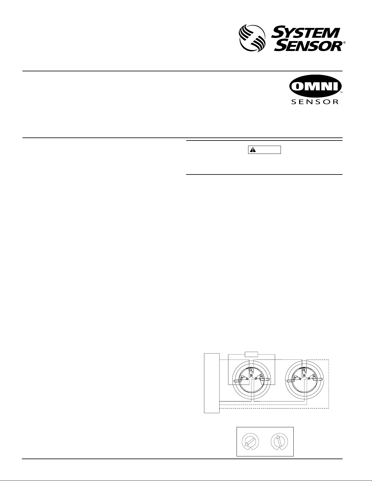
1. Wire the sensor base (supplied separately) per the wiring diagram (see
figure 1).
2. Set the desired address on the sensor address switches (see figure 2).
3. Install the sensor in the sensor base. Push the sensor into the base
while turning it clockwise to secure it in place.
4. After all sensors have been installed, apply power to the control unit
and activate the communication line.
5. Test the sensor(s) as described in the TESTING section of this manual.
D200-57-00 1 I56-749-05
Dust covers provide limited protection against airborne dust particles during shipment. Dust covers must be removed before the sensors can sense
smoke. Remove sensors prior to heavy remodeling or construction.
Testing
Before testing, notify the proper authorities that the system is undergoing
maintenance and will be temporarily out of service. Also, disable the system to prevent unwanted alarms. All sensors must be tested after installation and periodically thereafter. Testing methods must satisfy the
Authority Having Jurisdiction (AHJ). Sensors offer maximum performance
when tested and maintained in compliance with NFPA 72.
The sensor can be tested in the following ways:
A. Functional Magnet Test (Model M02-04-01)
This sensor can be functionally tested using a test magnet. The test
magnet electronically simulates smoke in the sensing chamber, testing
the sensor electronics and connections to the control panel.
1. Hold the test magnet in the magnet test area as shown (see figure 3).
2. The sensor should alarm the panel.
Tw o LED’s on the sensor are controlled by the panel to indicate
sensor status. Refer to the control panel technical documentation
for sensor LED status operation and expected delay to alarm.
B. Sensitivity Test
The sensor contains an internal test which continually checks the sensitivity of the sensor. If the sensor moves out of its intended sensitivity
range, the sensor will transmit a trouble signal to the control panel.
C. Smoke Entry: Aerosol Generator (Gemini 501)
The GEMINI model 501 aerosol generator can be used for smoke entry
testing. Set the generator to represent 4%/ft. to 5%/ft. obscuration as
described in the GEMINI 501 manual. Using the bowl shaped applicator, apply aerosol until the panel alarms.
Figure 1. Wiring diagram:
+
CONTROL PANEL
–
UL LISTED COMPATIBLE
–
+
Figure 2. Rotary decade address switch:
3825 Ohio Avenue, St. Charles, Illinois 60174
REMOTE ANNUNCIATOR
+–
3
4
3
2
1
0
1-800-SENSOR2, FAX: 630-377-6495
CAUTION
2
1
OPTIONAL RETURN LOOP
5
9
4
3
6
7
2
8
1
0
5
6
8
9
2
3
7
1
A78-2461-00
A78-2460-00
Page 2
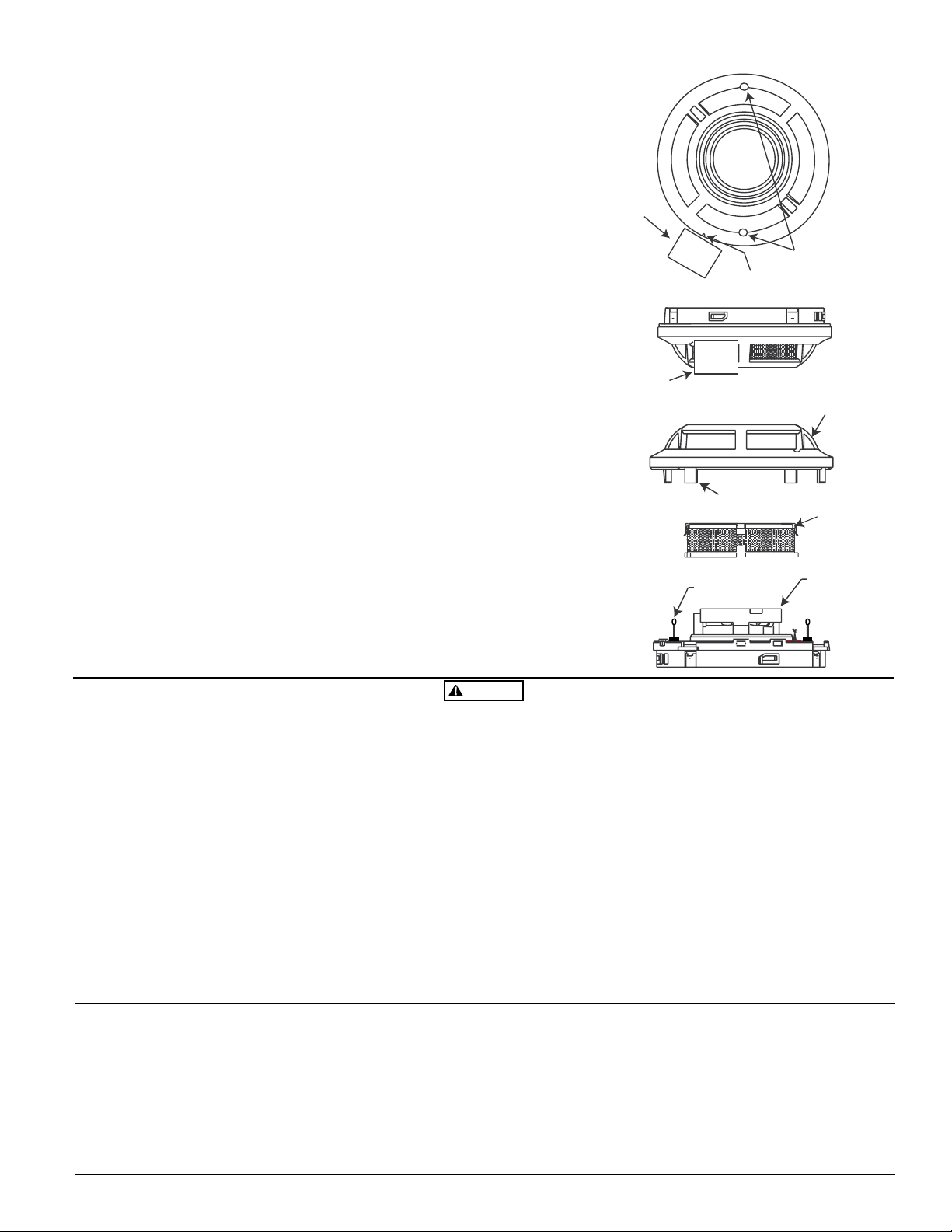
D. Direct Heat Method (Hair Dryer of 1000-1500 watts).
A hair dryer of 1000-1500 watts should be used to test the thermistors.
Direct the heat toward either of the two thermistors (see figure 4),
holding the heat source approximately 12 inches from the detector in
order to avoid damaging the plastic housing. The detector will reset
only after it has had sufficient time to cool. Make sure both thermistors are tested individually.
Both smoke and heat detection testing are recommended for verifying system protection capability.
A sensor that fails any of these tests should be cleaned as described under
CLEANING and retested. If the sensor fails after cleaning, it must be replaced and returned for repair. When testing is complete, restore the system to normal operation and notify the proper authorities that the system
is back in operation.
Cleaning
Before cleaning, notify the proper authorities that the system is undergoing maintenance, and will be temporarily out of service. Disable the system to prevent unwanted alarms.
1. Remove the sensor to be cleaned from the system.
2. Remove the sensor cover using a small standard screwdriver to release
each of the four cover removal tabs that hold the cover in place. Use
caution to avoid damaging the thermistors.
3. Vacuum the outside of the screen without removing it.
4. Remove the outer chamber assembly being careful not to damage the
thermistors. Pull the assembly straight away from the sensing chamber
until it snaps out of place. Use a vacuum or clean compressed air to
clean the inside of the outer chamber assembly.
5. Use a vacuum or clean compressed air to remove dust and debris from
the sensing chamber.
6. Reinstall the outer chamber assembly. Align the arrow on the outer
chamber assembly with the arrow on the printed circuit board. Push
the outer chamber assembly over the sensing chamber until it snaps
into place. Check to make sure that the screen is in the screen contact.
7. Reinstall the sensor cover. Use the thermistors and LED’s to align the
cover with the sensor. Snap the cover into place. Check to make sure
the thermistors are in the upright position.
8. Reinstall the sensor.
9. When all the sensors have been cleaned, restore system operation for
testing purposes and test the sensor(s) as described in the TESTING
section of this manual.
Figure 3. Test magnet position:
PAINTED
SURFACE
PAINTED
SURFACE
Figure 4. Thermistor positions:
TEST
MAGNET
THERMISTOR
MAGNET TEST
MARKER
TEST
MAGNET
COVER REMOVAL
TABS
T
N
I
A
P
T
O
N
O
D
LED STATUS
INDICATORS
OUTER CHAMBER
SENSING
CHAMBER
COVER
ASSEMBLY
WARNING
The Limitations of Property Protection Smoke Detectors
The smoke detector used with this base is designed to activate and initiate emergency
action, but will do so only when it is used in conjunction with an authorized fire alarm
system. This detector must be installed in accordance with NFPA standard 72.
Smoke detectors will not work without power. AC or DC powered smoke detectors
will not work if the power supply is cut off.
Smoke detectors will not sense fires which start where smoke does not reach the
detectors. Smoldering fires typically do not generate a lot of heat which is needed to
drive the smoke up to the ceiling where the smoke detector is usually located. For
this reason, there may be large delays in detecting a smoldering fire with either an
ionization type detector or a photoelectric type detector. Either one of them may
alarm only after flaming has initiated which will generate the heat needed to drive
the smoke to the ceiling.
Smoke from fires in chimneys, in walls, on roofs or on the other side of a closed
door(s) may not reach the smoke detector and alarm it. A detector cannot detect a
fire developing on another level of a building quickly or at all. For these reasons, detectors shall be located on every level and in every bedroom within a building.
Smoke detectors have sensing limitations, too. Ionization detectors and photoelectric detectors are required to pass fire tests of the flaming and smoldering type. This
is to ensure that both can detect a wide range of types of fires. Ionization detectors
offer a broad range of fire sensing capability but they are somewhat better at detecting fast flaming fires than slow smoldering fires. Photoelectric detectors sense smoldering fires better than flaming fires which have little, if any, visible smoke. Because
fires develop in different ways and are often unpredictable in their growth, neither
type of detector is always best, and a given detector may not always provide early
warning of a specific type of fire.
In general, detectors cannot be expected to provide warnings for fires resulting from
inadequate fire protection practices, violent explosions, escaping gases which ignite,
improper storage of flammable liquids like cleaning solvents which ignite, other
similar safety hazards, arson, smoking in bed, children playing with matches or
lighters, etc. Smoke detectors used in high air velocity conditions may have a delay
in alarm due to dilution of smoke densities created by frequent and rapid air exchanges. Additionally, high air velocity environments may create increased dust contamination, demanding more frequent maintenance.
To keep your equipment in excellent working order, ongoing maintenance is required
per the manufacturer’s recommendations and UL and NFPA standards. At a minimum, the requirements of Chapter 7 of NFPA 72, the National Fire Alarm Code, shall
be followed. A preventative maintenance agreement should be arranged through the
local manufacturer’s representative. Though smoke detectors are designed for long
life, they may fail at any time. Any smoke detector, fire alarm equipment, or any component of that system which fails shall be repaired or replaced as soon as possible.
Three-Year Limited Warranty
System Sensor warrants its enclosed smoke detector to be free from defects in materials and workmanship under normal use and service for a period of three years from
date of manufacture. System Sensor makes no other express warranty for this smoke
detector. No agent, representative, dealer, or employee of the Company has the authority to increase or alter the obligations or limitations of this Warranty. The
Company’s obligation of this Warranty shall be limited to the repair or replacement
of any part of the smoke detector which is found to be defective in materials or workmanship under normal use and service during the three year period commencing
with the date of manufacture. After phoning System Sensor’s toll free number 800SENSOR2 (736-7672) for a Return Authorization number, send defective units postage prepaid to: System Sensor, Repair Department, RA #__________, 3825 Ohio
Avenue, St. Charles, IL 60174. Please include a note describing the malfunction and
suspected cause of failure. The Company shall not be obligated to repair or replace
units which are found to be defective because of damage, unreasonable use, modifications, or alterations occurring after the date of manufacture. In no case shall the
Company be liable for any consequential or incidental damages for breach of this or
any other Warranty, expressed or implied whatsoever, even if the loss or damage is
caused by the Company’s negligence or fault. Some states do not allow the exclusion
or limitation of incidental or consequential damages, so the above limitation or exclusion may not apply to you. This Warranty gives you specific legal rights, and you
may also have other rights which vary from state to state.
D200-57-00 2 I56-749-05
© System Sensor 1999
 Loading...