

Page 1
Power on. Detectors
on loop do not have
communication capability.
Power on. One or more
detectors on loop have
communication capability.
Power not applied or
module not operating
properly.
Detector on loop in alarm.
One or more detectors
out of sensitivity or in
Freeze Trouble.
Detectors on loop not
in alarm, maintenance
or Freeze Trouble.
Loop wiring fault.
EZ Walk Test mode.
Loop wiring normal.
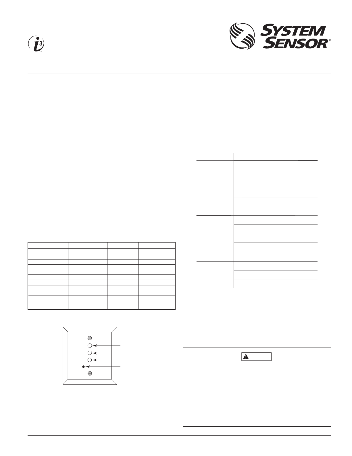
ON
Blink 1 sec. ON
and 1 sec. OFF
OFF
ON
Blink 1 sec. ON
and 1 sec. OFF
OFF
ON
Blink 0.5 sec. ON
and 0.5 sec. OFF
OFF
GREEN LED
RED LED
YELLOW LED
LED COLOR STA TUS
CONDITION
WARNING
Condition Maintenance relay (form C) Alarm relay (form A) Loop trouble relay (form A)
Normal OFF Open Close
Loop trouble OFF Open Open
Maintenance/Freeze trouble ON Open Close
Loop trouble and ON Open Open
Maintenance/Freeze trouble
Alarm OFF Close N/A
Alarm and loop trouble OFF Close N/A
Alarm and Maintenance/Freeze OFF Close N/A
trouble
Terminal Location T e rminal 7 – N.O. Relay connected Relay connected between
Terminal 8 – Common between terminals terminals 10 and 12
Terminal 9 – N.C. 10 and 1 1
Green LED
Red LED
Y e llow LED
EZ Walk-Test
Pushbutton
INSTALLATION AND MAINTENANCE INSTRUCTIONS
Series
Loop Test/Maintenance Module
Model: 2W-MOD2
I56-2174-004
3825 Ohio Avenue, St. Charles, Illinois 60174
1-800-SENSOR2, FAX: 630-377-6495
www.systemsensor.com
Before Installing
This information is included as a quick reference installation guide. Refer to the control panel installation manual
for detailed system information. If the modules will be installed in an existing operational system, inform the operator and local authority that the system will be temporarily
out of service. Disconnect power to the control panel before
installing the modules.
NOTICE: This manual shall be left with the owner/user of
this equipment.
General Description
The 2W-MOD2 allows a control panel to receive a “need for
maintenance” signal from two–wire i3 series smoke detectors, model numbers 2W–B, 2WT–B, 2WTA–B, and 2WTR–B.
The module uses a form C zone relay to initiate “out of sensitivity” and “freeze trouble”, a form A zone alarm relay and
a second form A zone relay to indicate loop fault (see Figure
1). An EZ Walk Test puts all detectors on the loop into a Walk
Test mode for easy verification of detector loop wiring.
Figure 1:
NOTE: If two–wire i3 detectors are used in conjunction
with a style D initiating circuit, the 2W–MOD2 must be
used to provide that capability. Ground fault on a mod-
ule’s two-wire loop can be indicated at a control panel if
the control panel is capable of ground fault detection on
the power supply to the module and meets NFPA 72 ground
fault indication requirements for initiating device circuits.
The installer must verify that capability.
Figure 3. Module LED modes:
Figure 2. Module front view:
Three LED’s on the module provide a local visual indication of the module status(es).
The maintenance module allows two-wire smoke detectors to
be used on any electrically compatible four-wire control panel.
D500-46-00 1 I56-2174-004
S0236-00
S0218-00
The module has loop trouble restoration detection. If the
loop trouble (open loop) doesn’t exist any more, the module will restore to standby condition with a maximum delay
of 1 minute. There is no delay in loop trouble detection.
If an alarm occurs while the module is indicating maintenance, the alarm will supercede maintenance.
If the green LED remains ON (no blinking) three minutes after applying power, it means that the module has determined
that no detector on its loop has communication capability.
In this condition, the detectors are still capable of initiating
alarm and loop trouble at the module. However, maintenance
and freeze trouble, will not be indicated at the module, and
EZ walk test will not be available. If i3 detectors are installed
on the loop, verify wiring and system operation.
Page 2
Control Panel
2W-MOD2
Aux. or
Smoke
Power
Fire Zone
Trouble Zone
Panel EOL
Panel EOL
12
11
10
9
8
7
1
2
3
4
5
6
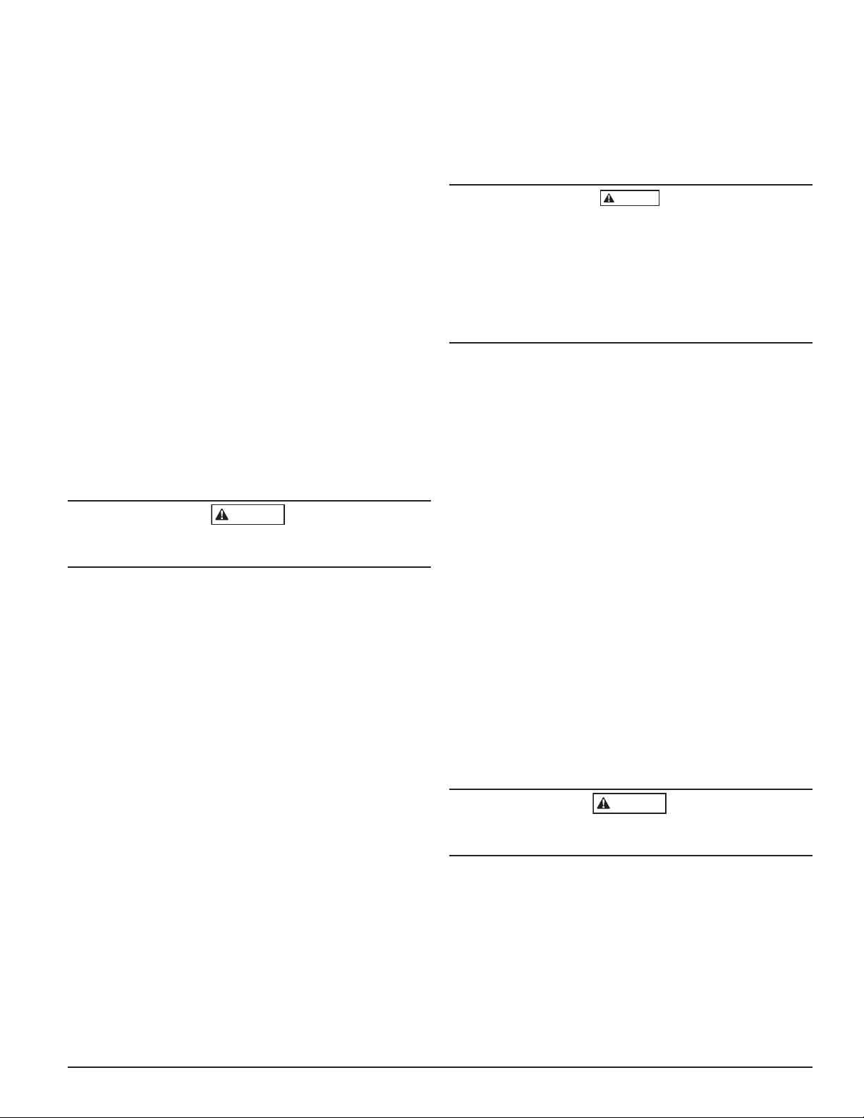
Loop Style D wiring
3.9 K� EOL (must not be
used for Style D)
A2143-10
+
–
+
–
Two-wire listed smoke
detectors. Do not mix
models on the same loop.
Only one 2WTR–B per loop.
Only one 2WTA–B per loop,
unless used with the RRS–MOD.
ALL CIRCUITS ARE SUPERVISED
AND MUST BE POWER LIMITED.
Control Panel
2W-MOD2
Aux. or
Smoke
Power
Fire Zone
Panel EOL
12
11
10
9
8
7
1
2
3
4
5
6
+
–
Loop Style D wiring
ALL CIRCUITS ARE SUPERVISED
AND MUST BE POWER LIMITED.
Two-wire listed smoke
detectors. Do not mix
models on the same loop.
Only one 2WTR–B per loop.
Only one 2WTA–B per loop,
unless used with the RRS–MOD.
3.9 K� EOL (must not be
used for Style D)
A2143-10
+
–
Control Panel
2W-MOD2
Aux. or
Smoke
Power
Fire Zone
12
11
10
9
8
7
1
2
3
4
5
6
+
–
Panel EOL
Loop Style D wiring
3.9 K� EOL (must not be
used for Style D)
A2143-10
+
–
Two-wire listed smoke
detectors. Do not mix
models on the same loop.
Only one 2WTR–B per loop.
Only one 2WTA–B per loop,
unless used with the RRS–MOD.
ALL CIRCUITS ARE SUPERVISED
AND MUST BE POWER LIMITED.
For NFPA loop Style D wiring the EOL resistor is provided
internal to the module. An external EOL resistor must
not be connected at the last detector on the loop (see Figures 5 – 7).
Compatibility Requirements
The 2W-MOD2 is marked with a compatibility/zone identifier as the last digit of a 5 digit code on the back of the unit.
To ensure proper operation, this module shall be connected
to compatible two-wire smoke detectors or the alarm contacts of four–wire i3 series detectors only. (Consult System
Sensor’s 2-wire compatibility guide).
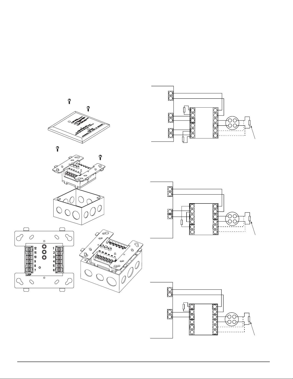
Figure 4. Mounting module
Wiring Diagram
Install module wiring in accordance with appropriate wiring diagrams (Figures 5 - 7). Reset is performed through
power inputs 1 and 2.
Figure 5. The Module Wiring: maintenance signal is
sent to a separate zone.
S0232-01
Figure 6. The Module Wiring: maintenance signal is
indicated at the panel as a fire trouble.
S0235-00
S0233-01
Figure 7. The Module Wiring: two-wire detectors to
four-wire panel conversion.
S0238-00
S0237-00
Mounting
Install in a dry indoor location. The 2W-MOD2 Maintenance Module mounts directly to 4 inch square electrical
boxes (supplied by installer). The box must have a minimum depth of 2 1/8 inches. Secure module to box as shown
in Figure 4.
D500-46-00 2 I56-2174-004
S0234-01
Page 3
CAUTION
WARNING
Wiring Installation Guidelines
WARNING
All wiring must be installed in compliance with the National Electrical Code, applicable state and local codes, and
any special requirements of the local authority having jurisdiction (AHJ).
Proper wire gauges should be used. The conductors used
to connect the module to the alarm control panel, smoke
detectors and accessory devices should be color-coded to
reduce the likelihood of wiring errors. Improper connections can prevent a system from responding properly in the
event of a fire.
The screw terminals in the mounting base will accept 14-24
gauge wire. For best system performance, all wiring should
be installed in separate grounded conduit; do not mix fire
alarm system wiring in the same conduit as any other electrical wiring. Twisted pair may be used to provide additional protection against extraneous electrical interference.
Wire connections are made by stripping about 1/4 inch of
insulation from the end of the feed wire, inserting it into
the proper terminal, and tightening the screw to secure the
wire in place.
Installation
Remove power from alarm control unit or initiating device
circuits before installing modules.
After all modules have been installed, notify the proper authorities that the system is in operation.
Testing
NOTE: Before testing, notify the proper authorities that
maintenance is being performed and the system will be
temporarily out of service. Disable the zone or system undergoing maintenance to prevent any unwanted alarms.
Modules must be tested after installation and following periodic maintenance. Testing should be performed at least
once a year.
Timing at Power-Up or Reset
Two minutes after power-up, the module will check for
communication, high maintenance, low maintenance, and
freeze trouble with each communication spaced 1 minute
apart. If a valid response to the communication check is
received, the module will check for freeze trouble every
4 hours, low and high maintenance every 24 hours, and
will recheck communication every 24 hours. Whenever the
module fails to receive a valid response to the communication checks, it will verify the result with another communication check one minute later. If it still fails to receive a
valid response, the module will cease to communicate until
a valid reset from the panel. In this mode, the module is still
able to detect alarm and wiring fault from the 2-wire loop.
NOTE: If an alarm occurs on the 2W-MOD2 zone before
the 2W–MOD2 has completed its power–up sequence, the
module’s green LED will remain on. To reset this condition,
the system must be reset and the module must be allowed
to complete its power–up sequence.
When using the RRS-MOD with model 2WTA-B, do not mix
the 2WTA-B with other model smoke detectors and dry contact closure devices, including mechanical heat detectors,
manual pull stations and waterflow switches. Such mixing
can cause a direct short on the auxiliary power terminals,
damaging the control panel’s internal circuitry and/or damage devices connected to the initiating device circuit.
EZ Walk Test
The 2W-MOD2 has a push button for EZ Walk Test mode
(see Figure 2.). The EZ Walk Test feature is available 6 minutes after power-up or panel reset. If the push button is
pressed momentarily the module will activate EZ Walk Test
for five minutes. All detectors on the loop should enter EZ
Walk Test mode. See i3 detector manual for detector response in EZ Walk Test mode.
NOTE: EZ Walk Test cannot be initiated if the Green LED
is not blinking.
If the 2W-MOD2 is in normal condition (Green LED blinking) and pressing the push button does not initiate EZ Walk
Test, wait one minute and try again.
At the end of the five minute period, the module will terminate EZ Walk Test and the yellow LED will stop blinking. The EZ Walk Test period can be extended by pressing
the push button a multiple number of times. For example,
pressing the push button N times will result in a Walk Test
duration of 5*N minutes.
If an alarm occurs during EZ Walk Test, the alarm condition
will supercede EZ Walk Test (alarm is the highest priority).
The EZ Walk Test shall not be used in lieu of functional testing (alarm, trouble and other functional tests) of the system.
If a module or detector fails the test, its wiring should be
checked. If the module still fails, it should be replaced.
Notify the proper authorities when the system is back
in service.
D500-46-00 3 I56-2174-004
Page 4

Specifications:
Electrical Mechanical
Supply Voltage - Min. 8.5 Volts (Power limited) Height: 4.5 inches
Max. 30 Volts (Power limited) Width: 4.0 inches
Max.Ripple Voltage: 30% of applied voltage Depth: 1.25 inches
Max. Standby Current: 30mA (12 detectors on loop) Weight: 0.5 pound
Max. Alarm Current: 90mA (Includes packaging
Alarm Contact Ratings: 0.5 Amp @ 36 V DC, Resistive materials)
Maintenance Contact Ratings: 2 Amp @ 30 V DC, Resistive
Min. Reset Voltage: 6 Volts
Min. Reset Time: 0.3 sec.
Operating Temperature Range: 14°F to 122°F (-10°C to 50 °C)
Operating Humidity Range: 0 to 95% RH non-condensing
Storage Temperature Range: –4°F to 158°F (–20°C to 70 °C)
Initial Communication Cycle: 2-6 minutes after power-up or panel reset
EZ Walk Test Available: 6 minutes after power-up or panel reset
2-wire compatibility
Min. loop voltage: 10 Volts
Max. loop voltage: 11.5 Volts
Max. loop resistance: 50 ohm
Max. loop ripple: 1 Vpp
Max. Loading Capacitance: 0.01 mF
Max. Alarm current: 40 mA
Max. Reset Voltage: 0.3 V
Alarm Delay: No
Min. Alarm reset time: 0.3 sec.
Max. normal load current: 1.25 mA
Zone Type: Standard
EOL Device: 3.9 KΩ (0.25W, 5%)
Loop style: B, D
Compatibility/Zone identifier: A
Max. detectors per zone: Models 2W–B and 2WT–B: 12
Model 2WTR–B: 1
Model 2WTA–B: 1
NOTE: When used with the RRS–MOD reversal relay/synchroniza-
tion module and the 2W–MOD2, a maximum of 12 2WTA–B detectors are allowed per zone.
Three-Year Limited Warranty
System Sensor warrants its enclosed product to be free from defects in
materials and workmanship under normal use and service for a period
of three years from date of manufacture. System Sensor makes no other
express warranty for the enclosed product. No agent, representative,
dealer, or employee of the Company has the authority to increase or alter
the obligations or limitations of this Warranty. The Company’s obligation of this Warranty shall be limited to the replacement of any part of
the product which is found to be defective in materials or workmanship under normal use and service during the three year period commencing with the date of manufacture. After phoning System Sensor’s
toll free number 800-SENSOR2 (736-7672) for a Return Authorization
number, send defective units postage prepaid to: System Sensor, Returns
FCC Statement
This device complies with part 15 of the FCC Rules. Operation is subject to the following two conditions: (1) This device may not cause harmful interference, and (2) this device
must accept any interference received, including interference that may cause undesired operation.
NOTE: This equipment has been tested and found to comply with the limits for a Class B digital device, pursuant to Part 15 of the FCC Rules. These limits are designed to provide reasonable protection against harmful interference in a residential installation. This equipment generates, uses and can radiate radio frequency energy and, if not installed
and used in accordance with the instructions, may cause harmful interference to radio communications. However, there is no guarantee that interference will not occur in a
particular installation. If this equipment does cause harmful interference to radio or television reception, which can be determined by turning the equipment off and on, the user
is encouraged to try to correct the interference by one or more of the following measures:
– Reorient or relocate the receiving antenna.
– Increase the separation between the equipment and receiver.
– Connect the equipment into an outlet on a circuit different from that to which the receiver is connected.
– Consult the dealer or an experienced radio/TV technician for help.
D500-46-00 4 I56-2174-004
©2006 System Sensor
Department, RA #__________, 3825 Ohio Avenue, St. Charles, IL 60174.
Please include a note describing the malfunction and suspected cause
of failure. The Company shall not be obligated to replace units which
are found to be defective because of damage, unreasonable use, modifications, or alterations occurring after the date of manufacture. In no
case shall the Company be liable for any consequential or incidental
damages for breach of this or any other Warranty, expressed or implied
whatsoever, even if the loss or damage is caused by the Company’s
negligence or fault. Some states do not allow the exclusion or limitation of incidental or consequential damages, so the above limitation or
exclusion may not apply to you. This Warranty gives you specific legal
rights, and you may also have other rights which vary from state to state.
 Loading...