

Page 1

System Q SIDE A - 27/02/04 Doc XVisionplus
VisionPlus Vari focal CCTV Camera INSTRUCTIONS
System Q E-mail support@systemq.com or fax support 01246 222 888
The all-new VisionPlus vari focal range of CCTV cameras -
Features
• Excellent Picture Quality
• Built in Varifocal Lens
• Dual Voltage or mains powered models
• 1/3” Sony SuperHAD CCD Sensor
• Two lens options 3.8-8mm & 9-22mm
• DSP chip-set
• BLC
• AGC
• AES
• High S/N Ratio
• Auto White Balance
• IR filter
The new range of Varifocal CCTV cameras offer outstanding performance at ordinary prices. With a choice of
colour, monochrome, 3.5-8mm or 9-22mm lenses and 12V DC, 24V AC, 240V AC options there’s a camera to
suit any application.
Installation and camera set up is easy with this installer friendly camera. All models in the range share the
same set up procedure so once you have learnt to fit one Varifocal model; you’ve learnt the entire range.
Models Covered by these ins tructions;
Colour
CCT555 12V DC / 24V AC 3.5-8mm Lens B&W
CCT556 240V AC 3.5-8mm Lens B&W
CCT557 12V DC / 24V AC 9-22mm Lens B&W
CCT558 240V AC 9-22mm Lens B&W
Monochrome
CCT550 12V DC / 24V AC 3.5-8mm Lens Colour
CCT551 240V AC 3.5-8mm Lens Colour
CCT552 12V DC / 24V AC 9-22mm Lens Colour
CCT553 240V AC 9-22mm Lens Colour
Varifocal Lens
This is a design of lens that has a range of manual focal length adjustments. It is strictly not a zoom lens
because it has quite a short focal length. They are usually used in situations where a more precise adjustment
of the scene in view is required which may fall between two standard lenses. They are also useful where for a
small extra cost one camera may be specified for all the cameras in a system. This saves a lot of installation
time and the cost of return visits to change lenses if the views are not quite right. For companies involved in
many small to medium sized installations such as retail shops and offices this can save on stockholding. It
makes the standardisation of systems and costing much easier.
Diagram of the Varifocal camera range.
Page 2
System Q SIDE B - 27/02/04 Doc XVisionplus
VisionPlus Vari focal CCTV Camera INSTRUCTIONS
System Q E-mail support@systemq.com or fax support 01246 222 888
Stage 1 – Powering the camera.
Powering 12V DC & 24V AC models; CCT550/552/555/557
When powering the camera with a 12V DC power supply, ensure that the supply is regulated and has a
continuous rating of 200mA or higher per camera. It is recommended to use a
power supply that is rated at 300mA; this prevents the PSU from running at its
maximum rating for long periods of time.
Note: These cameras incorporate a bridge rectifier on the power supply input
therefore there is no correct polarity in which the camera must be connected to
the supply.
WARNING – This PSU MUST NOT be a 13.8V security type used in intruder
alarms as the over voltage may damage the camera and void the warranty.
The earthing arrangement of an intruder type alarm PSU may give rise to
problematic “earth-loop” and poor voltage regulation, which can give poor/noisy
image quality. We offer no technical support or warranty with the camera if it
is powered by a 13.8V intruder alarm PSU, as it is contrary to the installation
and usage instructions of the camera.
If you are using the System Q Easy Connection Kit (CCT806/7) to power and connect your camera (12V models
only) please proceed as per the instructions supplied with The Easy Connection Kit. You will need to cut off the
DC Plug ONLY and use the bare wires to connect to the terminal strip. The 12V positive is the RED wire the 0V
is the BLACK wire.
Powering 240V AC models – CCT551/553/556/ 558
When using the Varifocal 240V AC models you will need to power them using 240V AC.
WARNING – 240V AC MAINS VOLTAGE CAN KILL. UNDER NO CIRCUMSTANC ES UNDERTAKE TO CONNECT OR INSTALL
THESE MAINS OPERATED CAMERAS UNLESS YOU ARE SUFFICIENTLY QUA LIFIED OR COMPETENT. YOU SHOULD NEVER
WORK ON MAINS EQUIPMENT WITHOUT FIRST ISOLATING THE SUPPLY F OR YOUR OWN AND OTHERS SAFETY.
The CT551/553/556/558 range of cameras come with a two core power flex coming out of the rear of the
camera, this should be connected as follows:
Blue = Neutral
Brown = Live
NOTE - As the CCT551/553/556/558 are mains rated electrical equipment they should be connected in
accordance with the latest IEE wiring regulations.
When the camera is connected correctly the LED on the rear will illuminate to indicate power is on.
Video Out.
The video output from the camera is provided from the BNC connector located at the rear of the camera. The
video output from the camera should be carried back to the monitor or control equipment via a suitable cable,
usually RG-59 or similar.
Remember that the Video output from the camera is like any other electrical circuit and requires two wires to
complete the circuit. When using a co-ax type cable such as RG59 or similar, the outer braid of the co-ax
provides the
A typical connection would be as follows;
Page 3

System Q SIDE C - 27/02/04 Doc XVisionplus
VisionPlus Vari focal CCTV Camera INSTRUCTIONS
System Q E-mail support@systemq.com or fax support 01246 222 888
It is recommended that when you are first setting up the cameras that you use a short BNC-BNC cable to link
the camera directly to the monitor and to set it up at the same time. This allows you to both understand the
camera and get the very best out of this great product, as you will be able to adjust the camera whilst looking at
the monitor screen. Obviously whilst you are setting up the camera, it does need to be powered!
Setting up the lens.
When setting up the lens to suit your particular application, remove the
top, loosen the locking screws and alter the focal / tele/wide
adjustments. When the desired picture is located tighten the locking
screws and replace the top.
There are two sections to the lens that can be modified, the focal
adjustment that allows you to alter the position of the focal lens in order to
focus the lens. The tele/wide adjustment allows you to achieve the
required angle.
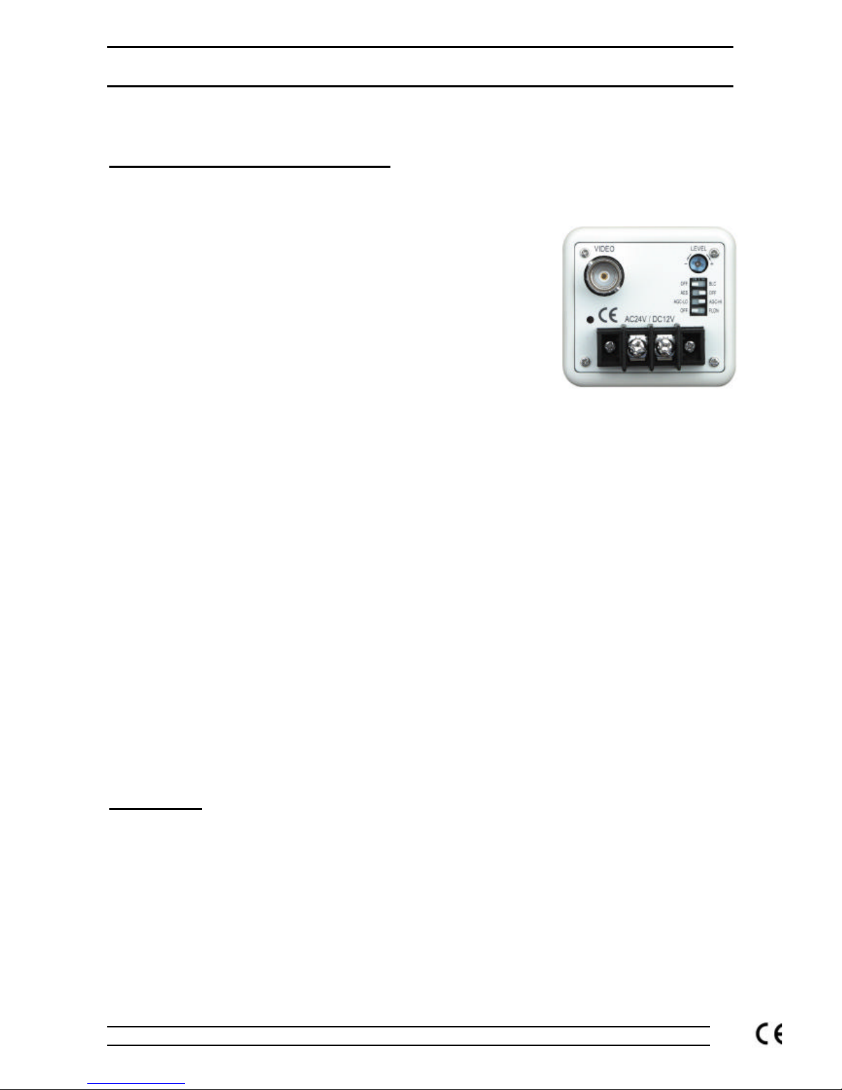
Dipswitches
On the rear of the camera are four dipswitches, see diagram below
1. Back Light Compensation (BLC).
BLC helps the camera when it is looking at a bright object such as an external window. The BLC tries to
compensate for the bright part of the image so that some of the surrounding area is not too dark.
2. Automatic Electronic Shutter (AES) also called electronic iris.
It is recommended that this is switched off when using this camera (unless you replace the lens for manual
iris type), because the lens itself would not be able to adjust for varying light levels. If you leave it switched
on the camera will still function but the picture quality will be erratic being too bright or too dark with poor
colour reproduction as both the camera and the lens would be fighting to compensate for varying light
levels.
3. Automatic Gain Control (AGC)
When the light falling on to an imaging device reduces to a certain level, there is insufficient to create a full
level video signal. AGC acts to increase the amount of amplification in these conditions to bring the signal
up to the required level. As well as amplifying the video signal, additional noise can be introduced, and the
signal to noise ratio reduced. The result is frequently a very much-degraded signal and poor picture on the
monitor.
4. Flicker - less Function (FL)
Set the dipswitch OFF/FLON to FLON to
enable the flicker - less function, when in
this mode, the AES/OFF switch is
automatically disabled.
Page 4

System Q SIDE D - 27/02/04 Doc XVisionplus
VisionPlus Vari focal CCTV Camera INSTRUCTIONS
System Q E-mail support@systemq.com or fax support 01246 222 888
Trouble shooting.
The camera is built to the highest standards and every unit is fully tested prior to packing so if you experience
an installation problem you need to investigate your cabling, connections, power supply and monitor. If you do
fail to get a picture on a monitor you need to check the following things.
No Picture
The camera cannot function without the correct working power supply. The power supply must be regulated
and be capable of supplying 200mA per camera CONSTANTLY.
For the 12V DC camera range. To check that the power supply is functioning correctly use a multimeter set on
DC volts (above 12V) and connect the probes to the power supply’s output. The meter should read between 1213V. If the meter shows a negative voltage the PSU could be wired incorrectly or you may have the meter
leads reversed. To ensure the multimeter is working correctly, connect it to a known voltage and polarity such
as a battery. If you find that supply is giving out more than 13V you may be using a non-regulated power
supply and must stop using it with the camera immediately or it may cause permanent damage to it.
Ensure that the BNC-BNC lead that you connect between the camera and monitor has no shorts or open
circuits. If you are making your own BNC-BNC lead, don’t forget the lead must have two wires connected to
complete the circuit, Video and Ground. If in doubt swap your lead for a pre-wired commercial one, as faulty
leads are the main cause of problems.
Interference on the camera picture
This is usually caused by poor or inadequate cabling, not observing the correct wiring techniques and for 12V
DC cameras the use of unregulated or poorly regulated power supply. If you want a good picture quality and
require the camera to work to its full potential, do not use an intruder alarm PSU with 12V DC cameras. If you
suspect you have a PSU problem with a 12V DC camera, the best way to check this is to power your system
using a fully charged 12V lead acid battery to give 12V totally regulated supply. If this solves the problem then
you need to change the PSU for a better quality one.
Picture is out of focus
Remove the top of the camera, loosen the locking screws and vary the focal adjustment until the picture is in
focus.
All specifications are approximate. System Q reserves the right to change any product specification or features without
notice. Whilst every effort is made to ensure that these instructions are complete and accurate, System Q cannot be
held responsible in any way for any losses, no matter how they arise, from errors or omissions in these instructions, or
the performance or non-performance of the camera or other equipment that these instructions refer to.
 Loading...