

Page 1

System Q SIDE A - 24/01/05 Doc XCCT465/475
CCT465/475 Varifocal Anti-Vandal CCTV Dome Camera INSTRUCTIONS
System Q E-mail support@systemq.com or fax support 01246 222 888
Varifocal A uto Iris With Anti-Vandal Features CCD Dome Camera
Introduction
Each of the Varifocal anti-vandal dom es is made from met al
and polycarbonate so they are resistant to moderat e impacts.
For extra security you can also purchase the anti-tamper
screw kit, which prevents unauthorised access, order code
CCT463
Its tough out er shel l i s also weatherproof ed so that the uni t can
be installed internally or externally when using the external
weatherproof cabl e glands provided.
The Varifocal lens means that the cameras can be adjusted f or
a wide angle of v iew or a narrow angle distance shot so they
can capture the exact scene your customer wants without you
havi ng to worry about what lens to order.
The cameras electronics have been designed around the latest
semiconductor technology and circ uit design to ensure that all three
vari ants of the cam era produce an excel lent picture qual ity to mat ch
the cameras stunni ng looks.
Features
• The combi nation of metal and polycarbonate give a tough
anti-vandal dome camera
• Dual input suppl y, 12V DC or 24V AC power supply required
• The dome cover is secured with 4 x Allen screws (Allen key
supplied) f or a professional and more secure installation.
• W ith a 4 -9mm Vari-focal lens being fitted as standard the lens size guesswork for installations has
been removed.
• Spare polycarbonate dome cov er (clear) av ailable. Vandal ised domes can be repaired quickly
mini mising time and expense, order code CCT464
• Domes can be mounted internally or externally (fitted wit h gasket s as standard)
• Supplied with a mounting plate for secure fix on suspended/false ceilings. (Fixing screws for the
dome and plate included)
• Nylon retaining strap between cover and base for added safety during installation and/or servicing.
• Video and power connected via a flying lead. The video is via a female BNC connector. T he power
is via a 2-way connector (cable mounted plug fi t ted and the socket is included) to reduce installat ion
time.
• Rubber base gasket supplied to fit between the base and mounting surface of the dome. Helps to
prevent dust and moisture ingress.
• Fixing template included. (Label showing the domes fixing hole positions)
Note: The Fixing hole di ameter for the flush mount range is 90mm
Models Covered in these instructions
CCT465 Flush Mount Hi-Res B&W with Vari-Focal Lens
CCT467 Flush Mount Mi d-Res Colour Dome with Vari -Focal Lens
CCT469 Flush Mount Hi-Res Colour Dome With Vari-F ocal Lens
CCT475 Surface Mount Hi-Res B&W Dome with Vari-Focal Lens
CCT477 Surface Mount Mid-Res Colour Dome with Vari-Focal Lens
CCT479 Surface Mount Hi-Res Colour Dome wit h Vari-Focal Lens
Page 2
System Q SIDE B - 24/01/05 Doc XCCT465/475
CCT465/475 Varifocal Anti-Vandal CCTV Dome Camera INSTRUCTIONS
System Q E-mail support@systemq.com or fax support 01246 222 888
Camera Specifications
CCT465/CCT475 CCT467/CCT477 CCT469/C CT479
Camera Spec Hi-Res B&W Med-Res Colour Hi-Res Colour
Image Sensor 1/3” B&W 1/3” Col. Sharp 1/3” Col. SONY Ex View
Image Out put
1V
pk-pk
75Ω 1V
pk-pk
75Ω 1V
pk-pk
75Ω
Resolution 600T VL min 380TVL mi n 480TVL mi n
Min Illumination 0.03 Lux 0.5 Lux 0.25 Lux
Input Volt age Range 12V DC / 24V AC 12V DC / 24V AC 12V DC / 24V AC
Power Consumption 200/100 mA 200/ 100 mA 200/100 m A
Lens 4-9mm Vari-focal 4-9mm Vari-focal 4-9mm Vari-f ocal
AGC Automatic Automatic Automatic
Iris Control Auto Iris Auto Iris Auto Iris
Size W125 x D125 x H95mm W125 x D125 x H95mm W125 x D125 x H95mm
Powering the Camera
The dome cam eras are dual v ol tage i .e. you can use them on a 12V DC system or a 24V AC system. The
camera has bui lt in power supply control circui t for ease of connec tion; thi s means that you can connect to
any 12VDC or 24VAC system wit hout worrying about polarity or vol tage regulation.
The camera is provided with a screw terminal on a fly lead that allows you to connect the power supply to it.
When poweri ng the camera with a 12V DC power supply, ensure that the supply is regulat ed and has a
continuous rati ng of 100m A or higher per camera. It is recom mended to use a power supply that is rated
higher than the current consum ption of the camera i .e. POW 100 would be adequate for powering a single
camera but when powering t wo or more you should look at the bi gger power supplies that are available from
System Q; this prevents the PS U from runni ng at its maximum rati ng for long periods of time.
If you are using the System Q Easy Connection Kit (CCT 806/7) to power and connect your camera (12V
models onl y) pl ease proc eed as per t he i nstruc t i ons suppli ed with T he Easy Connecti on Ki t . You wil l need to
cut of f the DC Plug ONLY and use the bare wires to connect to the termi nal strip. T he 12V positiv e is the
RED wire the 0V is the BLACK wire.
Using 24V AC power
Using a suitable cable between the 24V AC power supply (POW600) and the camera you can connect the
power to the cameras terminal stri p either way around. As the power is 24V AC, (alternating current), the
polarity is not important . You must use a separate cable f or power and video. It is recommended you use a
2/4-core cabl e t o carry the AC power to the camera and use an RG59 or twisted pair cable to bring the video
signal back from the cam era to the monitor / control equipm ent.
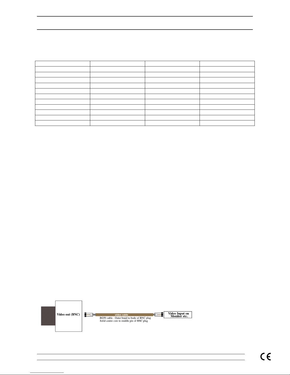
Connecting the camera to control equipment.
The dome cam era com es with a f l y l ead f or power and v i deo out. To reduce instal lat ion ti me the v i deo out
lead is t erminated i nt o a male BNC connector. Thi s al l ows the instal l er t o effortl essly connec t the camera to
control equi pment via a femal e BNC-BNC lead.
Remember that the Video out from the cam era is like any other el ectrical ci rcuit and requires two wires to
complet e the circuit. When using a co-ax type cable such as RG59 or similar, the outer braid of the co-ax
provides the “0V GROUND” connection and the inner core provides the “Video” connection.
It is recommended that when you are first setting up the cameras that you use a short BNC-BNC cable to
link the camera directly to the monitor and to set it up at the same time. This allows you to both understand
Page 3
System Q SIDE C - 24/01/05 Doc XCCT465/475
CCT465/475 Varifocal Anti-Vandal CCTV Dome Camera INSTRUCTIONS
System Q E-mail support@systemq.com or fax support 01246 222 888
the camera and get the very best out of this great product, as you will be able to adjust the camera whilst
looking at the monitor screen. Obviously whilst you are setting up the camera, it does need to be powered!
Lens Adjustment
When setting the l ens to suit your particul ar appli cation, remov e the cov er and inner lens surround, loosen
off the locking screws and alter t he focal / Tel e/wide adjustments. W hen the desired picture is achiev ed
tighten the locking screws and replace the covers.
There are two secti ons to the lens that can be m odified, t he focal adjustm ent that allows you to alter the
position of the focal lens in order to f ocus the lens. The Tel e/wide adjustment allows you to achiev e the
required angle.
Hint: When you are sett ing up t he cameras on sit e it pays t o have a t est monitor w ith you so that whilst you
are up ladders, you can posit ion the lens wit hout having to go up and dow n to the monitor to check on the
camera setting. CCT020 4” LCD Test Monitor or the CCT021 6.8” LCD Test Monitor
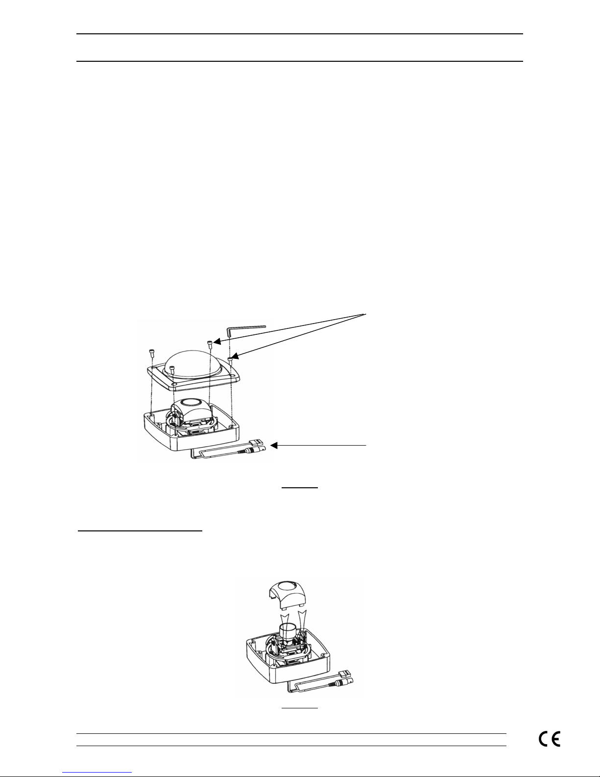
Accessing the Dome Camera
(For Lens adjustments and Dipswitch settings, Figure 3 and Table 1)
Refer to F igure 1
Figure 1
Using the All en key provided with the Dome, undo and remove the 4 Allen screws. The dome cover can
now be lift ed clear of the housing giving access to the camera lens and PCB.
Adjusting the Lens settings.
The black pl astic cover lifts off of the camera. It i s hel d by 4 plastic lugs and just needs easing from its
mountings and l ifting upwards to ex pose the camera PCB, switches and the lens focus and zoom controls.
(Refer t o F igure 2)
Figure 2
The 4 Allen screws secure
the Dom e cover.
BNC and Power
Connections
Page 4

System Q SIDE D - 24/01/05 Doc XCCT465/475
CCT465/475 Varifocal Anti-Vandal CCTV Dome Camera INSTRUCTIONS
System Q E-mail support@systemq.com or fax support 01246 222 888
The pins adjust the focus and the angle of view or tele/wide angles. To change the focus or angl e the pins
need to be loosened by turni ng t hem counter clock wise. When the correct focus and picture is achieved
then re-tighten the locking screws to hold the sett ings in place. See Figure 3 for the lens pi n locations.
The Dipswitch settings
(Refer t o figure 4 and Table1)
The dipswitches are numbered 1-3. There are 2 positions for the dipswitches, either ON or OFF.
Switches 1 and 2 are for the Auto-Iris setti ngs of the lens. Switch 3 i s for the BLC (Back Light
Compensation).
The common settings for the switches when the Auto Iris lens is fitted are shown in Figure 4 (Please Note
that this l ens i s fitted as standard)
(Please refer to Table 1 for t he complete dipswitch settings.)
Figure 3
Table 1
Function SW1 SW2
Electronic Iris (ESC)
OFF OFF
AUTO IRIS (ALC)
ON ON
FL (Flicker Less)
OFF ON
SW3= BLC
OFF= BLC is OFF ON = BLC is ON
ESC
The electronic iris setting would be used i f a standard or manual iris lens is being used. This relies on the
electroni cs built into the camera PCB to electronically set the correct picture brightness.
ALC
The Auto Iris setting is used when the lens has the Automati c Iris functi on. This is fitted as standard on the
camera. T he ALC control may need to be adjusted for this l ens i f the picture is too bright or poor at night.
This control is only eff ective when the Aut o Iris lens is fitted and the dipswitches set accordingly. (See the
Automatic Level Control section f or further details)
FL
The FL or Fl icker Less switch is used if there appears to be ‘pulsing’ or ‘flickering’ on the picture. Setting the
switches as in table 1 (SW1 OFF and SW2 ON) removes the problem.
Back Light Compensation (BLC)
This option can help when there is something bri ght in the main picture such as an external window. The
symptom s may show some of the objects in the picture as silhouettes.
Setting t his to ON allows the lens to compensate for the bright part of the picture so that the surrounding
area of the picture is not too dark.
Page 5

System Q SIDE E - 24/01/05 Doc XCCT465/475
CCT465/475 Varifocal Anti-Vandal CCTV Dome Camera INSTRUCTIONS
System Q E-mail support@systemq.com or fax support 01246 222 888
Automatic Level Control (ALC)
Figure 4
Note: If the camera is giving satisfactory pictures t hen there is no need to adjust the ALC control.
The ALC setting determines when the IRIS of a lens opens and closes. Turning the control counter
clockwise al lows the IRIS to open, which in turn allows in more li ght producing a brighter pi cture. Turning the
control clockwise allows the IRIS to close producing a dark picture.
The best way to set up the ALC is with t he cam era i n the bri ght est li ght condi t ions that it wil l be operat i ng in
i.e. sunli ght and keep the IRI S open to its m axim um without gi vi ng too bright a pi cture. T his means at low
light levels the IRIS will be as open as possible giving the best results.
Use the following method to adjust the ALC control.
Tip:
Set-up the ALC with the camera in its brightest working conditions. This will gi ve the best overall operati on
of the Iris for varying light levels.
1. Turn the ALC control fully counter clockwise. The picture on the monitor should be very bright or
white.
2. Slowly turn the ALC control cl ockwise until the pict ure is as required.
Locking Pi ns for
Lens Adju stment
Dipswitches
The ALC (Automatic
Level Control)
Page 6

System Q SIDE F - 24/01/05 Doc XCCT465/475
CCT465/475 Varifocal Anti-Vandal CCTV Dome Camera INSTRUCTIONS
System Q E-mail support@systemq.com or fax support 01246 222 888
Installation Overview
Installation Tips:
Tip 1: With reference to the Int ernal gasket that seals between the domes cover and base. Spread a thin
coat of silicon grease onto the lip of the dome and seal prior to fi xing the cover (this is a simple
precautionary measure that will assist the seal s properties and also aid removal for future serv icing).
Tip 2: With reference to the rubber grommet that is used for cable entry. Use silicon sealant or another t ype
of sealant wit h the same or similar properties to seal around the cables and entry hole.
Figure 5 below shows you how to replace the polycarbonate dome insert – order code CCT 464
Figure 5
Figure 6 below gives a diagrammatic representation of how to fasten the Dome to a false/suspended ceiling.
Page 7

System Q SIDE G - 24/01/05 Doc XCCT465/475
CCT465/475 Varifocal Anti-Vandal CCTV Dome Camera INSTRUCTIONS
System Q E-mail support@systemq.com or fax support 01246 222 888
Figure 6
Trouble-shooting Tips
Picture too bright or d ark:
• The ALC control is set incorrectly
• The BLC switch needs setting
• The camera is set for Electronic Iris and not Auto Iris
No Picture.
• Check the supply voltage to t he camera. This can be anywhere between 12-24volts ac/dc
• Check the BNC video lead connect ion. Remember that like any other electrical system the vi deo
signal requires a 2-wir e connec tion. The centre cor e carries the video signal and the outer core or
screen is the ‘video signal return’
Poor Night Time Pictures:
• Check the dipswitch configurati on, the camera is suppli ed with an auto iris lens as standard and they
should be set for Aut o Iris and not Electronic Iris.
• Check the set-up of the camera in its brightest operati ng conditions and adjust the ALC cont rol as
described in the instructions.
• Check there i s suf ficient lighting available for the area under observation, if it is not possible t o see
anything in the dark yourself i t is unlikely that the camera wil l see anything either. TIP: Take a lead
lamp to the sight and try recording the picture with the light in different places; this will help
solve or highlight any lighting issues.
Poor Focus:
• Check the lens adjustments for focus and set for best possible picture as requi red.
Page 8

System Q SIDE H - 24/01/05 Doc XCCT465/475
CCT465/475 Varifocal Anti-Vandal CCTV Dome Camera INSTRUCTIONS
System Q E-mail support@systemq.com or fax support 01246 222 888
• Check the ALC control. This controls the iris aperture and if it is too open t hen t he picture will not be
sharp. This is best set-up in the brightest operating conditions. See the ALC section.
• Check that t he dome cover is clean.
• Check that t here is or has been no moisture ingress through a poor seal or cable entry. This usually
leav es tell tale smears on the inside of the dom e cover.
 Loading...