

Page 1
System Q SIDE A - 24/01/05 Doc XCCT455
CCT455/7/9 Varifocal CCTV Dome Camera INSTRUCTIONS
System Q E-mail support@systemq.com or fax support 01246 222 888
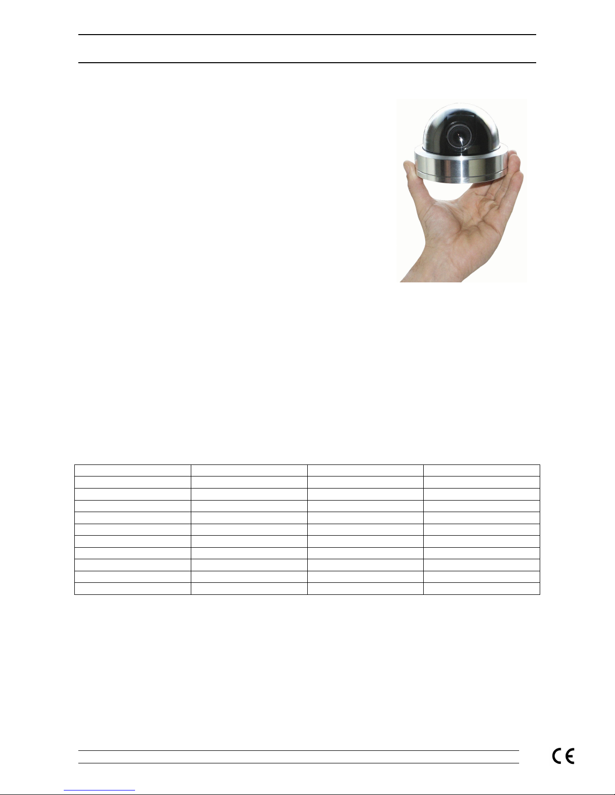
Varifocal Auto Iris CCD Dome Camera
Introduction
Each of the Varifocal dome has been engineered from a solid piece of
aluminium to produce a truly exceptional product.
With the domes stunning looks and great functionality you shouldn’t loose
many jobs
The beauty of this product is not just on the outside, the dome comes equipped
with a Varifocal lens that allows you to get the picture that your customer was
expecting when you are installing. It also has an auto iris lens, so when looking
at a doorway the camera will compensate for any bright sunlight.
The domes’ stunning looks means that they look the part in any environment.
Installed in a shop, office, bank, school or an industrial unit th e domes look and
perform great.
The Varifocal lens means that the cameras can be adjusted for a wide angle of
view or a narr ow angle d istan ce shot so th ey can captur e the exa ct scene your
customer wants without you having to worry about what lens to order.
As the lens is auto-iris it can accommodate a wide range of lighting conditions improving the cameras perfor mance in
low light whilst also coping with bright sunlight or shop lights effortlessly.
The ca mer as elect roni cs ha ve been desi gned aroun d t he la test sem icon ductor techn ology an d circu it desig n to ensu re
that all three variants of the camera produce an excellent picture quality to match the cameras stunning looks.
Models Covered in these instructions
CCT455 Hi-Res B&W Dome with Var i-focal Lens
CCT457 Med-Res Colour Dome wit h Vari-focal Lens
CCT459 Hi-Res Colour Dome with Vari-focal Lens
Camera Specifications
Camera Spec Hi-Res B&W Med-Res Colour Hi-Res Colour
Image Sensor 1/3” B&W 1/3” Col. Sharp 1/3” Col. SONY Ex View
Image Output
1V
pk-pk
75Ω 1V
pk-pk
75Ω 1V
pk-pk
75Ω
Resolution 600TVL min 380TVL min 480TVL min
Min Illumination 0.03 Lux 0.5 Lux 0.25 Lux
Input Voltage Range 12V DC / 24V AC 12V DC / 24V AC 12V DC / 24V AC
Power Consumption 200/100 mA 200/100 mA 200/100 mA
Lens 4-9mm Vari-focal 4-9mm Vari-focal 4-9mm Vari-focal
AGC Automatic Automatic Automatic
Iris Control Auto Iris Auto Iris Auto Iris
Size, Dia x H 110mm dia x 80mm H 110mm dia x 80mm H 110mm dia x 80mm H
Mounting the Camera
Th e d o me ca me ra s ar e su p plie d w it h a fix ing pla t e a nd dr illing t e mpla t e th at a llo w to fix you r do me
camera (using the screws supplied) to wood or brick with wall plugs (not supplied) or to
plasterboard / suspended ceilings with bolts and fixing plate (supplied).
Powering the Camera
The dome cameras are dual voltage i.e. you can use them on a 12V DC system or a 24V AC system. The camera has
built in power supply contr ol circuit for ease of connection ; this means that you can connect to any 12VDC or 24VAC
system without worrying about polarity or voltage regulation.
The camera is provided with a screw terminal on a fly lead that allows you to connect the power supply to it.
Page 2
System Q SIDE B - 24/01/05 Doc XCCT455
CCT455/7/9 Varifocal CCTV Dome Camera INSTRUCTIONS
System Q E-mail support@systemq.com or fax support 01246 222 888
When powering the camera with a 12V DC power supply, ensure that the supply is regulated and has a continuous
rating of 100mA or higher per camera. It is recommended to use a power supply th at is rated higher than the current
consumption of the camera i.e. POW100 would be adequate for powering a sin gle camera but when powering two or
more you should look at the bigger power supplies that are available from System Q; this prevents the PSU from
running at its maximum rating for long periods of time.
If you are using the System Q Easy Connection Kit (CCT806/7) to power and conn ect your camera (12V models only)
please proceed as per the instructions supplied with The Easy Connection Kit. You will need to cut off the DC Plug
ONLY and use the bare wires to connect to the terminal strip. The 12V positive is the RED wire the 0V is the BLACK
wire.
Using 24V AC power
Using a suitable cable between the 24V AC power supply (POW600) and the camera you can connect t he
power to the cameras terminal strip either way around. As the power i s 24V AC, (alternating current), the
polarity is not important. You must use a separate cable for power and video. It is recommended you use a
2/4-core cabl e t o carry the AC power to the camera and use an RG59 or twisted pair cable to bring the video
signal back from the camera to the m onitor / control equipment.
Connecting the camera to control equipment.
The dome camera comes with a fly lead for power and video out. To reduce installation time the video out lead is
terminated into a male BNC connector. This allows the installer to effortlessly connect the camera to control
equipment via a female BNC-BNC lead.
Remember that the Video out fr om the camera is like any other electrical circuit and requires two wires to complete
the circuit. When using a co-ax type cable such as RG59 or similar, the outer braid of the co-ax provides the “0V
GROUND” conn ection a nd the inner core provid es the “Video” connection.
It is recommended that when you are first setting up the cameras that you use a short BNC-BNC cable to link the
camera directly to the monitor and to set it up at the same time. This allows you to both understand the camera and get
the very best out of this great product as you will be able to adjust the camera whilst looking at the monitor screen.
Obviously whilst you are setting up the camera, it does need to be powered!
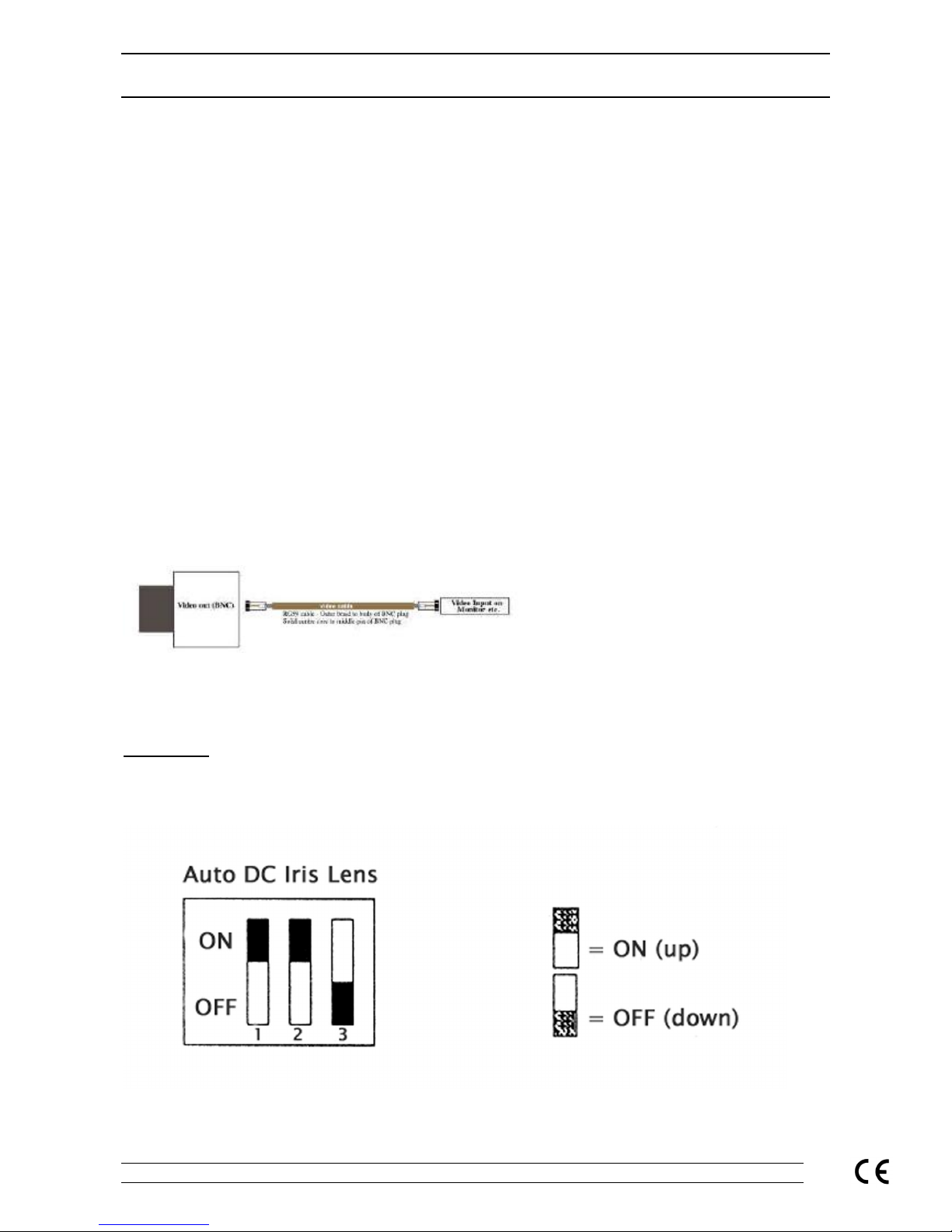
Dipswitches
The CCT455 has a bank of four dipswitches.
The CCT457 (Mid Res Col our) has three dipswitches:
Switch 1 Electronic Iris
Switch 2 Auto Iris
Switch 3 Back Light Compensation
Page 3

System Q SIDE C - 24/01/05 Doc XCCT455
CCT455/7/9 Varifocal CCTV Dome Camera INSTRUCTIONS
System Q E-mail support@systemq.com or fax support 01246 222 888
The CCT459 (High Res Col our) has four dipswitches.
Switch 1 Iris Control (Auto Iris=ON, ESC=OFF)
Switch 2 Back Light Compensation (ON= BLC ON)
Switch 3 Automatic Gain Control (ON = ALC ON)
Switch 4 FL/Flicker less (ON = FL on)
1. Automatic Level Control / Electronic Shutter Control (ALC / ESC)
This must be set to ALC when using these cameras with the standard Auto Iris Lens. If switched to
ESC, the camera will sti ll function but the picture quali ty will be errat ic being too bright or too dark with
poor colour reproduction as both the cam era and the lens would be fight ing to compensate for v arying
light levels.
(The Elect ronic shutter control is driven from the electronics on the pcb, t he ALC relies on the
functioning of t he Auto Iris in t he lens.)
2. Back Light Compensation (BLC).
BLC helps the camera when it is looking at a bright object such as an external window. The BLC tries to
compensate f or the bright part of the image so that some of t he surrounding area is not too dark.
It is recommended always to be set to on.
3. Automatic Gain Control (AGC)
When t he light f alling on to an i maging dev ice reduces to a certai n level , there may be i nsuffi cient to
create a full level video signal. The AGC acts to increase the amount of amplification in these
conditions t o bri ng t he signal up t o the requi red level. As well as amplif yi ng the v i deo signal, additi onal
noise can be i ntroduced, and the signal to noise ratio reduced. The result can lead to a v ery muchdegraded signal and poor picture on the monitor.
4. Flicker - less Function (FL)
Set the dipswitch 4 FL to ON to enable the flicker - less function, when in this mode, the AES/OFF
switch is automat ically disabled.
Someti mes the picture can be seen to ‘Flicker’ or ‘Pulse’, setting thi s switch t o O N will prevent this
problem.
Lens Adjustment
When setting the l ens to suit your particul ar appli cation, remov e the cov er and inner lens surround, loosen
off the locking screws and alter t he focal / Tel e/wide adjustments. W hen the desired picture is achiev ed
tighten the locking screws and replace the covers.
There are two secti ons to the lens that can be m odified, t he focal adjustm ent that allows you to alter the
position of the focal lens in order to f ocus the lens. The Tel e/wide adjustment allows you to achiev e the
required angl e. The Tel e/wide adj ustment wil l ‘zoom’ into or away from t he object i n the pict ure, dependi ng
on how much of the area is required to be in view.
TIP: W hen you are setting up the cameras on site it pays to have a test moni tor with you so that
whilst you are up ladders to can position the lens without having to go up and down to the monitor
to check on the camera setting. CCT 020 4” LCD Test Monitor or the CCT021 6.8” LCD Test Monitor
Page 4

System Q SIDE D - 24/01/05 Doc XCCT455
CCT455/7/9 Varifocal CCTV Dome Camera INSTRUCTIONS
System Q E-mail support@systemq.com or fax support 01246 222 888
Trouble-shooting Tips
Picture too bright or dark:
• The ALC control is set incorrectly
• The BLC switch needs setting
• The camera is set for Electronic Iris and not Auto Iris
No Picture.
• Check the supply voltage to the camera. T his can be anywhere between 12-24volts ac/dc
• Check the BNC video lead connection. Remember that l ike any other electrical system the v ideo
signal requires a 2-wir e connec tion. The cent re core carries the video signal and the outer core or
screen is the ‘video signal return’
Poor Night Time Pictures:
• Check the dipswitch configuration, the cam era is supplied with an auto iris lens as standard and they
should be set for Aut o Iris and not Electronic Iris.
• Check the set-up of the camera in its brightest operat ing conditi ons and adj ust t he ALC control as
described in the instructions.
• Check there is sufficient lighting available for the area under observation, if it is not possible to see
anything in the dark yourself it is unli kely that the camera will see anything either. TIP: Take a lead
lamp to the site and try recording the picture with the light in different places; this will help
solve or highlight any lighting issues.
Poor Focus:
• Check the lens adjustm ents for focus and set for best possible pict ure as required.
• Check the ALC control. This controls the iris apert ure and if it is too open then the picture will not be
sharp. This is best set-up in the brightest operating conditi ons. See the ALC section.
• Check that the dome cover is clean.
• Check that there is or has been no moisture ingress through a poor seal or cable entry. T his usually
leav es tell tale smears on the inside of t he dome cover.
 Loading...