


1
Modular Multi-source • ZAM40 Zone Amplifier
Installation
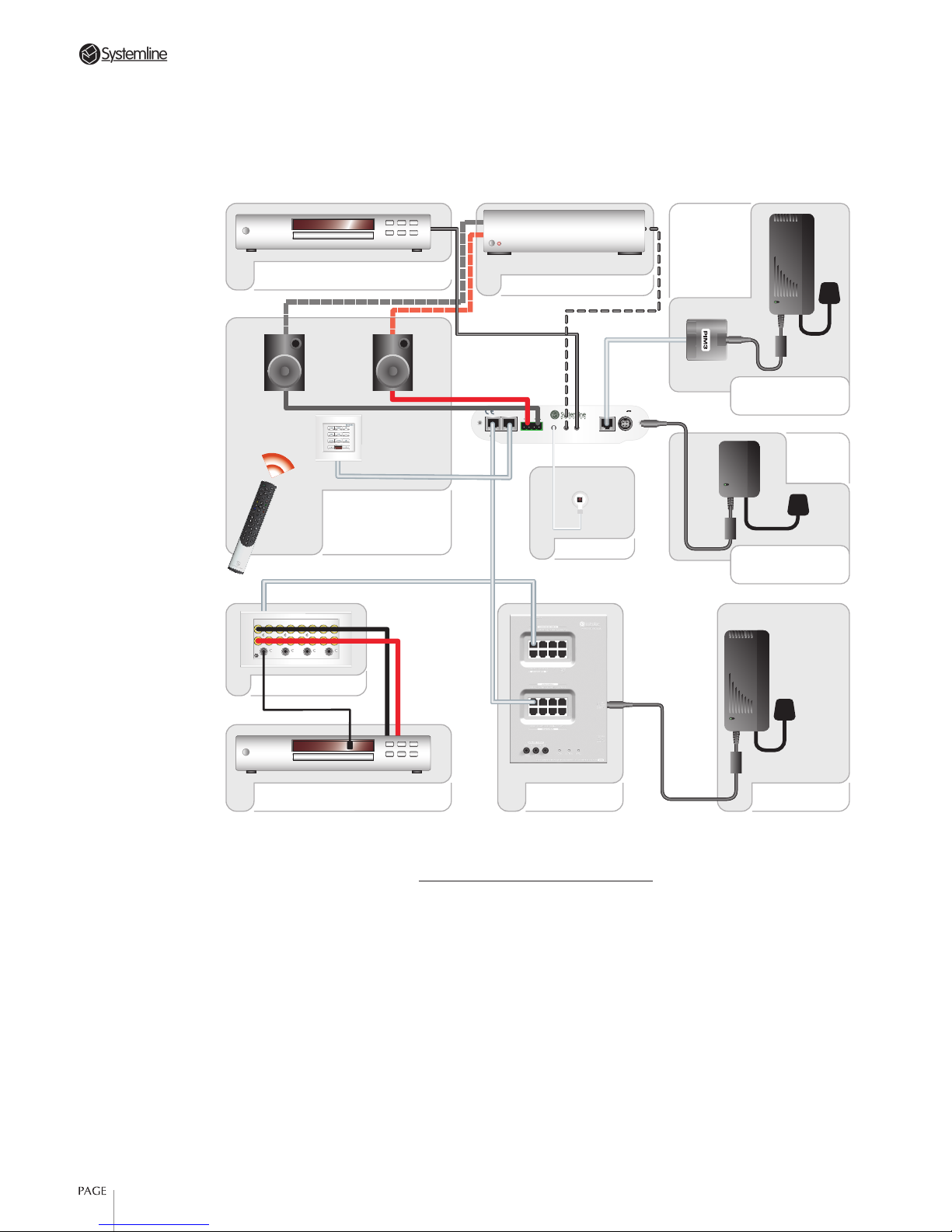
The Connection Diagram (Figure 1) shows
how all of the different connections on the
back of the ZAM can be used. The diagram
shows the use of Modular Multi-Source
equipment but the ZAM is equally at
home in a single source system.
Because it is such a versatile amplifier
there are several different configuration
levels to choose from and not all of the
amplifiers features may be needed.
Listed below are two of the most common
ways in which the installer might wish to
use the product:
1. As a direct substitute for ALM2
loudspeakers when using passive ceiling
speakers of a different brand
In this instance the ZAM will be connected
to the Hub via the System input from
which it will receive all necessary power,
audio and data connections.
The speakers should be connected in the
usual way using ordinary loudspeaker
cable. In order to control the amplifier
it will be necessary to employ either a
Keypad or single IR receiver (supplied)
and handset.
The ZAM can be easily fitted through the
ceiling cut out and sited in the ceiling
void next to the speakers. It is not even
essential to secure the ZAM in place as it
is small and light enough to sit between
the joists on the plaster board or ceiling
tiles; it gives off very little heat when
operational.
There is also the option in this
configuration to add a Remote Power
supply from a PIM, which will increase the
available audio power output
2.
As a Systemline Modular compatible
amplifier for use with traditional floor
standing or bookshelf Hi-fi speakers
For this configuration the ZAM will need
to be in the room near to the speakers.
The power audio and data can again be
provided from the Hub system input with
extra power available from a Local Power
input via a dedicated PSU130.
In this configuration it may be convenient
to add a local source component using
a phono to stereo jack lead (QED J2P
optional) on the line-input socket. If
required, the ZAM can be used as a
control amplifier because the pre-out will
drive most power amplifier inputs. Again
a choice should be made whether to use a
Keypad and handset or IR receiver to send
commands to the amplifier.
The best place to site the amplifier is to fix
it to the wall using the screws provided.
The lettering on the front and rear panels
is optimised for this orientation, however
it is also possible to site the amplifier on a
table top and rubber feet are provided for
this purpose.
Using the ZAM
The ZAM is ready to use straight out
of the box with no need to make any
configuration settings. It will respond to
commands from single and multi-source
Systemline handsets and keypads in
exactly the same way as the ALM2 Active
Ceiling Speaker.
Once powered up and connected into a
system the ZAM will display a red power
LED to indicate standby. The amplifier is
activated by sending either the standby
command from a Systemline Modular
handset or Keypad or a specific source
command from the multi-source versions
of both.
ZAM40 Zone Amplifier
The ZAM 40 amplifier is designed for use with a Systemline Modular Multi-Room Audio Distribution
System only. Specifically it is intended for use where standard active ceiling speakers are not required.
It can be integrated into the system in exactly the same way as the active ceiling speaker but requires
the addition of separate passive speakers. The ZAM can be mounted in the ceiling void or on the wall.
Like the active ceiling speakers the ZAM utilises the latest Class D amplifier technology to deliver the
high fidelity of a class AB amplifier with the low power consumption and space saving features that
result from its 90% efficiency.
2
Modular Multi-source • ZAM40 Zone Amplifier
Figure 1: ZAM40 Connection Diagram
Power Amp (optional)
PSM130 PSU
MIM4
ZONE
Audio (control via
handset or keypad).
AM8 Audio Hub
LOCAL DC
POWER
REMOTE
POWER
LINE
INPUT
PRE-AMP
OUTPUT
IR-REC
INPUT
SPEAKERSKEYPAD
INPUT
SYSTEM
INPUT
DC SUPPLY
+30 V
@ 4.33 A
L R
DESIGNED IN THE UK
Power
Method 3
Power
Method 2
RR R
L
R
LL L
MIM4
IR 1 IR 2 IR 3 IR 4
IN OUT IN OUT IN OUT IN OUT
SOURCE 1 SOURCE 2 SOURCE 4
MULTI-SOURCE INPUT PLATE
SOURCE 3
RR R
L
R
LL L
MIM4
IR 1 IR 2 IR 3 IR 4
IN OUT IN OUT IN OUT IN OUT
SOURCE 1 SOURCE 2 SOURCE 4
MULTI-SOURCE INPUT PLATE
Remote Source
Local Source
IR Receiver
Right
Left
Power via PIM3
Powered directly
from PSM45

3
Modular Multi-source • ZAM40 Zone Amplifier
In each instance the blue System LED will
light indicating that the system source
has been selected and the status is also
displayed at the keypad. To switch to the
LOCAL or Line input source press L on the
keypad or remote and the green LED will
display.
Pressing STANDBY will toggle the ZAM
back through SYSTEM and a further press
takes the amplifier into Standby again.
Volume level is altered by the familiar up
and down keys with mute being engaged
by the mute key and disengaged by
pressing VOLUME UP.
Configuring the ZAM
The ZAM can be configured for different
digital address, turn on volume, max
volume, bass and treble levels just like
any regular Modular speaker.
In order to access this mode of operation
and adjust these different parameters refer
to the instructions, which are included
with the relevant handset or keypad that
you wish to use.
Output Power and different power supply
options
Use the table below to choose which
power up option to use:
Power Supply
Input
Output Power
System 10W
Remote
Power
22W
Local DC 22W
!
Note: Do not connect remote power
and local power simultaneously.
Technical Specifications:
Maximum Power Output
22W rms. into 4-7Ω @ 1% THD +N
(local power supply connected).
Minimum speaker impedance
4Ω
Frequency Response
20Hz – 20kHz
Total Harmonic Distortion
<0.5% @ 5W/Channel
S/N Ratio
80dB
Power Supply Requirements
30V DC (PSU130 or Hub)
Net Weight
0.5kg
Dimensions
185x40x108mm
Note: All specifications are subject to
change.
Note: This equipment has been tested and
found to comply with the limits for a Class
A digital device, pursuant to part 15 of
the FCC Rules. These limits are designed
to provide reasonable protection against
harmful interference when the equipment
is operated in a commercial environment.
This equipment generates, uses and can
radiate radio frequency energy and, if not
installed and used in accordance with the
instruction manual, may cause harmful
interference to radio communications.
Operation of this equipment in a
residential area is likely to cause harmful
interference in which case the user will be
required to correct the interference at his
own expense.

ZINS111-ISS1.00-220405
 Loading...