

Page 1
MULTI-ROOM SYSTEM
S4.3
S4.3
MULTI-ROOM SYSTEM
Installation Manual
Page 2
PAGE
This symbol is to alert the
user of the presence of
dangerous voltages inside
the enclosure of the S4.3
Controller. To reduce the
risk of electric shock do not
remove any parts of the
S4.3 Controller.
This symbol is to alert the
user of important operating
instructions in the owner's
information accompanying
the S4.3 Controller.
Read all the instructions before connecting or
operating the S4.3 Controller. Pay particular
attention to the safety information. Keep this
manual so you can refer to these safety
instructions.
WARNING: There are no user serviceable parts
inside. Refer all servicing to qualified service
personnel.
WARNING: To reduce the risk of fire or electric
shock, do not expose the S4.3 Controller to
moisture or water. Do not allow foreign objects
to get into the enclosure. If the unit is exposed
to moisture, or a foreign object gets into the
enclosure, immediately disconnect the power
cord from the wall. Take the unit to a qualified
service person for inspection and necessary
repairs.
Clean the S4.3 Controller only with a dry cloth or
a vacuum cleaner.
Place the S4.3 Controller on a fixed, level surface
strong enough to support its weight. Keep the
S4.3 Controller away from radiators, heat
registers, stoves, or any other appliance that
produces heat.
Safety
GUARANTEE
All products are covered by a 2 year Return to Base guarantee for parts and labour. Site visits are
not covered by this guarantee and will normally result in a call out charge if such a visit is
requested or deemed necessar
y.
Although we have endeavoured to make this manual as comprehensive as possible, it does not
cover every aspect of every possible system installation. Please feel free to call our Technical
Service Department if you have any questions.
If the S4.3 Controller is placed in an enclosure,
there must be sufficient ventilation of the
enclosure to allow proper cooling.
Connect the S4.3 Controller to the power outlet
only with the supplied 3-pin grounded power
supply cable or an exact equivalent. The cable
should be connected to a properly grounded 3pin wall outlet. Do not modify the supplied cable
in any way. Do not use extension cords.
Do not route the power cord where it will be
crushed, pinched, bent at severe angles, exposed
to heat, or damaged in any way. If the cable
shows any sign of wear or damage, immediately
stop using it and obtain a proper replacement
from a qualified service agency or from the
Systemline service department.
If the S4.3 Controller shows signs of improper
operation, or if it has been dropped or damaged
in any way, immediately disconnect the power
cord from the wall. Take the S4.3 Controller to a
qualified service person for inspection and
necessary repairs.
Page 3
PAGE
1 Overview 1
1.1 Basic Architecture 1
1.2 Controlling the Remote Zones 1
1.3 System Flexibility 1
1.4 Systemline Highlights for Installers 1
2 Component Description 3
2.1 S4.3 Controller 3
2.2 RHS IR Remote Control 4
2.3 DMS Module 4
2.4 KMS Keypad 5
2.5 Data Cable and Connectors 5
2.6 Speaker and Cable Connections 5
3 System Planning 6
3.1 Initial Considerations 6
3.2 S4.3 Controller Basic Set-up 7
3.21 Placement 7
3.22 Connections 7
3.23 IR “Flood” Emitter 8
3.24 IR Emitter Jacks & Cabling 8
3.25 N/C Jack 8
3.3 Zone Configuration 9
3.31 Basic Zone Complement 9
3.32 Control Code Generators 9
3.33 Loudspeakers 9
3.34 Zone Splitters 9
3.4 A/V Wiring 10
3.41 Recommended Configuration 10
4 Installation Guide 11
4.1 The S4.3 Controller 11
4.11 Source connections 11
4.12 Speaker Cable Connections 12
4.13 Preamp Outputs 13
4.14 Data Cable Connections 13
4.15 Paging Input 14
4.2 Zone Control Devices 15
4.21 DMS Module 15
4.22 The KMS Keypad 16
4.23 Fitting DMS & KMS Modules 17
4.3 Zone Connection Strategies 19
4.4 Zone Splitter Connection 20
5 System Set-up 21
5.1 A.C. Line Considerations 21
5.11 A.C. for the S4.3 Controller 21
5.12 A.C. for Source Components 21
5.13 Multi-Controller Control Link 21
5.14 External Control of A.C. Mains Outlets 21
5.15 A.C. Power Recommendations 21
5.2 Source Component Setup 21
5.21 Default Operating Mode 22
5.22 Optional Operating Modes 22
5.23 Set-up Sequence 23
5.3 IR System and Control Codes 24
5.31 Overview 24
5.32 Front Panel IR Flood Emitter 25
5.33 Rear Panel IR Emitters 25
5.4 Advanced Multi-Zone Systems 25
5.41 8 - and 12 - Zone Systems 25
5.42 Large System Configuration 25
5.43 Source Connections 26
5.44 IR Flood Emitter Connections 26
5.45 IR Repeater Connections 27
5.46 RC-5 Bus Connection 27
5.47 IsoLink Connection 27
5.48 A.C. Connections 27
5.49 Engaged Operation 27
5.5 Paging Operation 28
5.51 Paging Inhibit 28
5.6 Configuring the Pre-Out Sockets 28
6 Operation 29
6.1 Preliminary Observations 29
6.2 RHS Hand-held Remote Control 29
6.21 Input Selector Buttons 30
6.22 Tuner (Source 1) Control Buttons 30
6.23 CD (Source 2) Control Buttons 30
6.24 Tape/Satellite or Cable (Source 3)
Control Buttons 30
6.25 VCR/DVD/Tuner 2/CD 2 (Source 4)
Control Buttons 31
6.26 VOLUME UP, VOLUME DOWN 31
6.27 MUTE 31
6.28 STBY 32
6.29 “X” 32
6.3 KMS Keypad 32
6.31 Key Functions 32
6.32 System Commands 33
6.33 T uner (Source 1) Commands 33
6.34 CD (Source 2) Commands 33
6.35 Tape/Satellite or Cable (Source 3)
Commands 33
6.36 VCR/DVD/Tuner 2/CD 2 (Source 4)
Commands 34
6.4 DMS Module 35
6.41 Overview 35
6.42 Controls and Indications 35
6.43 Dot Matrix Display 35
6.44 Operation 36
6.45 Setting Alarms and Time 36
6.46 Zone Splitter Control 37
7 Specification 38
QED Faxback 39
Table of Contents
Page 4

PAGE
1.1 Basic Architecture
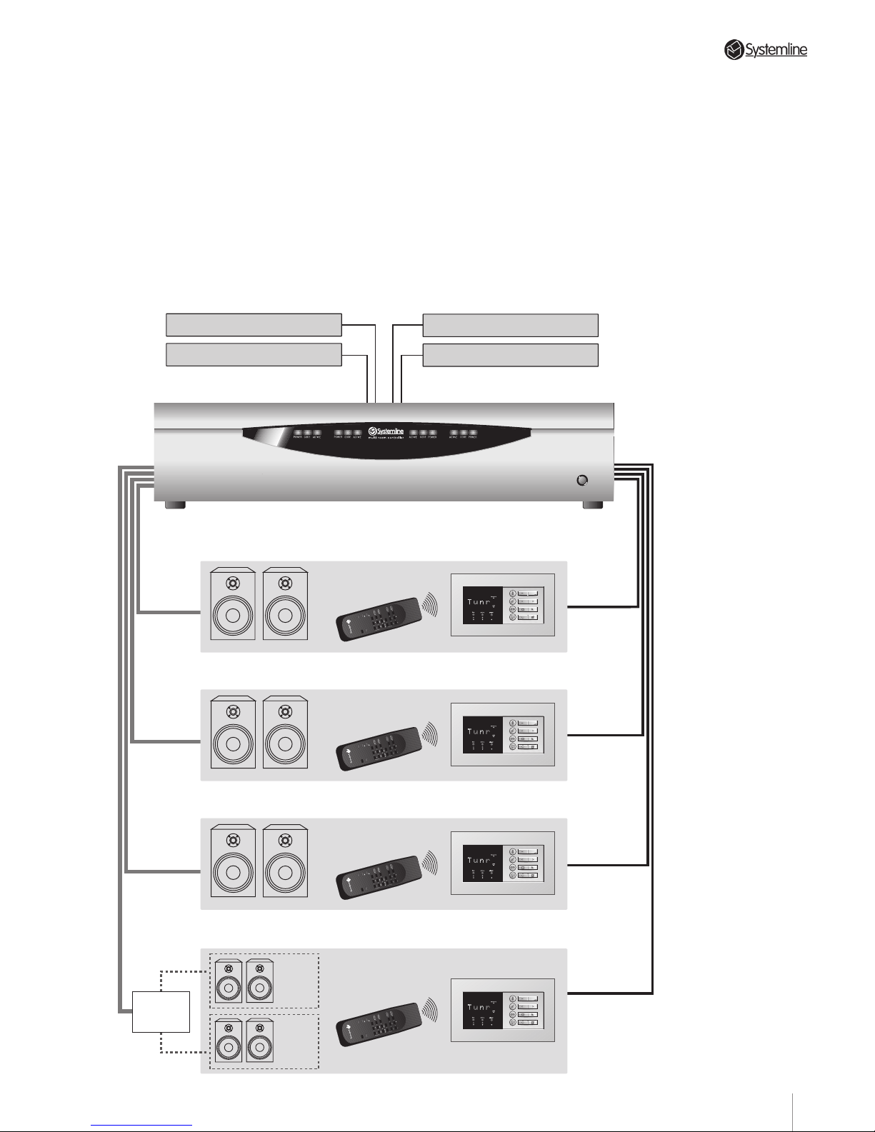
The Systemline S4.3 Controller MultiRoom Control System distributes audio
signals from a single set of source
components to as many as four
separately controlled remote zones or
listening areas. The centrally located S4.3
Controller contains source selection,
microprocessor controlled
communications circuitry and
independent preamplifier/power amplifier
sections for all zones. Each zone has a
pre-amp output which can be configured
as either fixed or variable output. A
number of equipment source codes are
held within the controller enabling instant
compatibility with the most popular
component brands.
1.2 Controlling the Remote
Zones
Users can select either of two ways to
control remote zone operation. The first is
the RHS hand-held remote. This
generates infra-red (IR) control pulses
read by the wall-mounted DMS module.
The DMS module then transmits
commands to the S4.3 Controller through
hard-wired connections.
The second method uses the optional
wall-mounted KMS keypad to transmit
commands directly to the S4.3 Controller.
The KMS is also hard-wired to the S4.3
Controller.
Users can select a combination of sensor
and keypad operation for any zone. The
system accepts inputs from up to two
DMS modules and three keypads (for a
total of five input devices) per zone.
1.3 System Flexibility
The Systemline S4.3 Controller MultiRoom Control System is exceptionally
flexible. In addition to the S4.3 Controller,
a simple two-zone system might include
just one RHS hand held controller/DMS
combination for one zone and one KMS
keypad in the second.
Additionally, any zone can drive two pairs
of speakers via the use of an optional
'Zone Splitter'. This enables two pairs of
speakers to be switched remotely using
the DMS display module.
In a more elaborate form, multiple
controllers can be used to form large
multi-zone systems with control from
many locations using remote handsets
and keypads.
1.4 System Highlights for
Installers
1) For keypad or handset operation - no time
consuming programming is required, Up to
three Keypads and three DMS modules can
be connected to any one zone simply by
daisy chaining one to the other .
2) All DMS modules and keypads are
interchangeable between zones for easy
installation. Simply set the DIP switch on
the DMS module to the zone address.
3) Built in equipment codes for RC-5, SONY,
PIONEER, YAMAHA, DENON, PACE,
NOKIA, PANASONIC, ROTEL, ONKYO,
TECHNICS, NAD, LUXMAN, GALAXY,
JERROLD and TOSHIBA components.
These are normally set up in a matter of
seconds with the remote handset,
although some options may require initial
resetting of switch SW1 on the Translator
Card within the S4.3 Controller. It is also
possible to use two CD players or tuners
with a controller providing in each case
that they are from different
manufacturers.
4) A Single-button operation for each source
selection and activation of Play
command.
5) The S4.3 Controller features an enhanced
a.c. control link. This enables the a.c.
mains outlets to be controlled from any
zone on any controller. In addition, an
external trigger can be used to activate all
controller a.c. outlets without the need to
activate a zone.
Section 1 • System Overview
1
Page 5
PAGE
Section 1 • System Overview
9) Zone splitters enable zones to be divided into
two areas.
10)Four infra-red 'window emitters' can be
plugged directly into dedicated mini jack
sockets.
11)Components featuring an RC-5 bus can be
plugged directly into a dedicated RC-5 output.
12)The TX configuration terminal allows multiple
controllers to be linked together, and still use
just one set of IR emitters.
6) All zones can be put into standby from
any zone on any controller in multiple
controller installations.
7) A built-in Paging input allows zones to
receive PA announcements or to Mute
when the doorbell rings!
8) The system incorporates a near universal
infra-red link which remains active even
when a zone is in standby. Simply point
any remote at a DMS module to relay the
command back to the source
components.
Living Room
Family Room
Kitchen
Bedroom
Area
1
Area
2
AB CD
TUNER
CD
FAV STN PRESETS
STOP SKIP
RANDOM DISC
TAPE/SATSTOP
VIDEO/LD
STOP
PAUSE CHNL
X
VOL
VOL
MUTE
STBY
TUNER
CD
FAV STN PRESETS
STOP SKIP
RANDOM DISC
TAPE/SATSTOP
VIDEO/LD
STOP
PAUSE CHNL
X
VOL
VOL
MUTE
STBY
TUNER
CD
FAV STN PRESETS
STOP SKIP
RANDOM DISC
TAPE/SATSTOP
VIDEO/LD
STOP
PAUSE CHNL
X
VOL
VOL
MUTE
STBY
TUNER
CD
FAV STN PRESETS
STOP SKIP
RANDOM DISC
TAPE/SATSTOP
VIDEO/LD
STOP
PAUSE CHNL
X
VOL
VOL
MUTE
STBY
ZONE
SPLITTER
D.V.D./L.D./V.C.R./C.D.2/Tuner 2
Compact Disc Player
AM/FM Tuner
Tape Deck/Satellite/Cable
2
Page 6

PAGE
2.1 S4.3 Controller
The S4.3 Controller is the heart of the
S4.3 Controller Multi-Room Control
System. It features:
•Four separate microprocessor-controlled
stereo preamplifier/power amplifier
sections, one for each remote zone
•PHONO inputs for up to four sources
•“Buffered loop through” PHONO outputs
for connection to additional controllers or
main system amplifier
• PHONO line level preamplifier outputs
(Fixed or variable output)
Four separate plug-in Line Drivers which
enable the volume output for each zone
to be configured as either variable or
fixed
• Quick Fit speaker plugs and sockets
• PHONO line level input/ output for paging
audio source
•Compatibility with industry standard,
screened CAT-5 cable using 6-way IDC
connectors (supplied)
•PHONO output for RC-5 remote
control protocol components (direct
connection via RC-5 bus)
•Four mini-jack IR emitter outputs
•One a.c. mains outlet with 400 W
capacity, switched to allow easy
remote control of total system
power if desired
•Front panel LED indicators for each
zone showing Power On/Off, status
and command pulse processing
•High power front panel IR “flood”
emitter to transmit remote zone
commands to associated source
components
•PHONO paging 'trigger' input for
activation by suitable telephone and
doorbell systems
Section 2 • Component Description
4
3
2
RC-5
N/C
AUDIO IN
AUDIO
OUT
IN
RIGHT
INPUTS
LEFT
OUTINOUT IN
OUT
IN
OUT
ZONE B
SPEAKERS
RIGHT
LEFT
ZONE C
WE1
WE2
WE3
WE4
TX-FORMAT
ZONE A
DATA
Conforms to EN55013 & EN50082-1.
E.M.C. Test Certificate No. 300/95
T
X
O
U
T
P
U
T
S
ZONE D
S4.3 MUTI-ROOM
CONTROL
LINK
IN OUT
230V AC
50Hz
POWER CONSUMPTION: 430W MAX
PRE/LINE-OUTPRE/LINE-OUTPRE/LINE-OUTPRE/LINE-OUT
TRIGGER
PAGING
AC OUTLET
230V 50Hz
SWITCHED TOTAL:
460W MAX
1
123456
DATA
123456
DATA
123456
DATA
123456
SPEAKERS
RIGHT
LEFT
SPEAKERS
RIGHT
LEFT
SPEAKERS
RIGHT
LEFT
123456
AB CD
3
Page 7
PAGE
Section 2 • Component Description
2.2 RHS IR Remote
Control
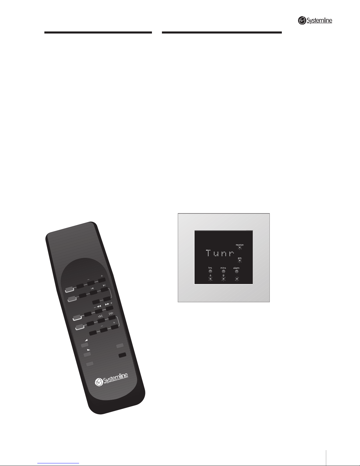
The RHS remote control serves a dual
purpose. In addition to providing
dedicated pushbuttons for the most
needed functions of both the S4.3
Controller and source components, it
also serves as a quick set-up tool
during initial configuration. Normal
operating mode is explained in
Section 6.2. Details of initial set-up
will be found in Section 5.23.
The RHS has a special high intensity
IR transmitter. In conjunction with the
system’s sensitive DMS modules, this
transmitter assures reliable operation
under a wide variety of conditions.
TUNER
CD
FAV STN PRESETS
STOP SKIP
RANDOM DISC
TAPE/SAT STOP
VIDEO/LD
STOP
PAUSE CHNL
X
VOL
VOL
MUTE
STBY
2.3 DMS Module
The wall-mounted DMS module receives
commands from the RHS hand-held
remote and, after processing to ensure
maximum data integrity, sends these
codes to the S4.3 Controller. When a zone
is active, the DMS normally displays the
selected source. During volume change or
muting, or on receipt of a Paging signal,
the DMS displays relevant status
indications. Pressing the Alarm button
(when the zone is active) will display the
time for a few seconds.
When a zone is at standby, the DMS
normally displays the time. During
activation or shutdown, an appropriate
message is displayed.
The DMS enables “A/B” speaker switching
when a Zone Splitter is installed.
You will find details of the display in
Sections 5.23 and 6.4.
NOTE: A DMS module connected to the
zone A data input MUST be used during
initial set-up, particularly with systems
where non RC5 source components are
included. Details are in Section 5.23.
4
Page 8
PAGE
2.4 KMS Keypad
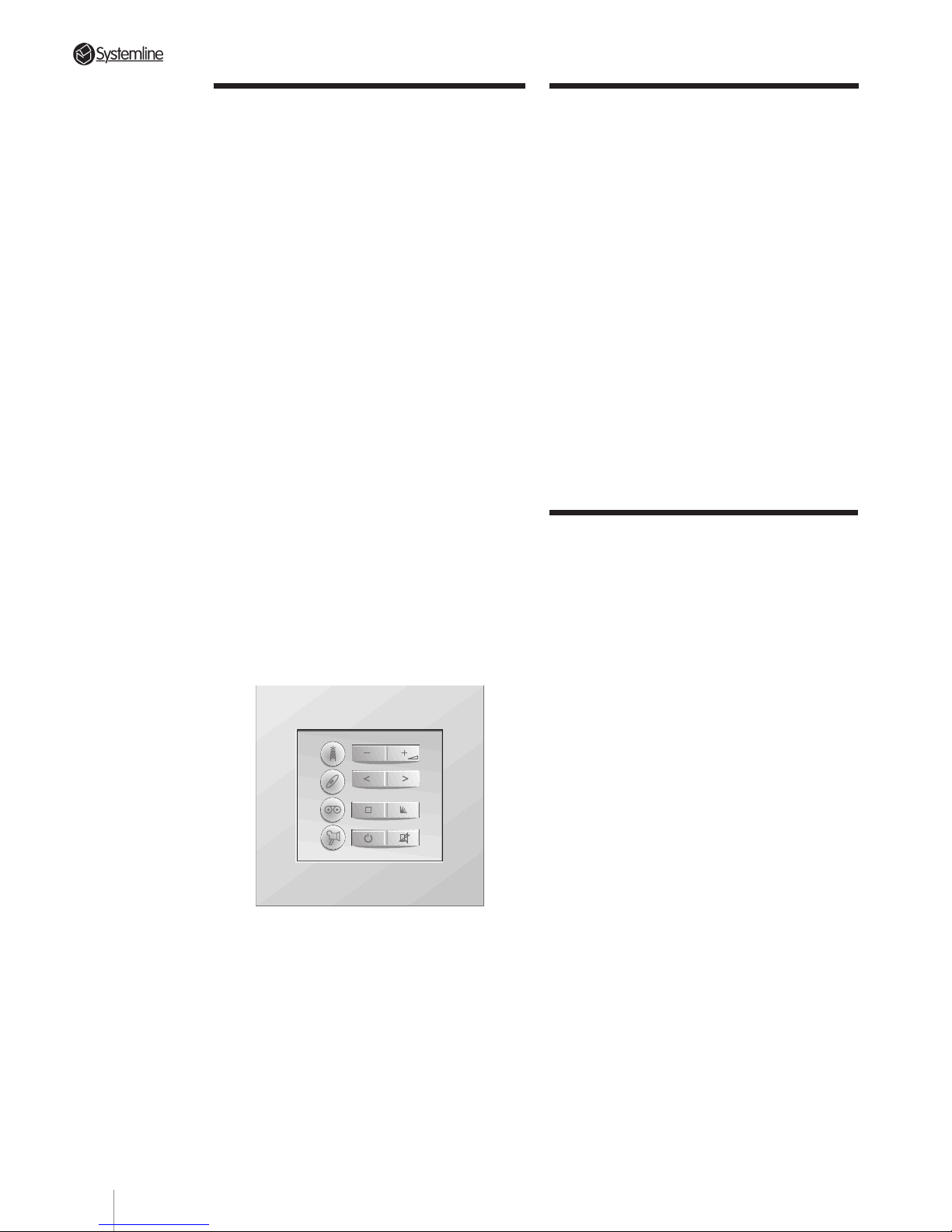
The KMS keypad provides a remote zone
control alternative to the RHS. The keypad
can be used as a stand-alone control
device although it is most functional with
the DMS module. Its design is the
optimum balance between flexibility and
simplicity.
The four left-hand keys are each used to
select a pre-programmed source. When a
selection is made, the zone is activated
automatically if necessary. Of the four
right-hand keys, the upper and lower keys
provide volume control (upper key) and
standby and mute selections (lower key)
for any selected source. The functions of
the two centre keys change automatically
depending on the selected source. Refer
to Section 6.3 KMS Keypad for further
information.
The KMS mounts conveniently in a
standard single wall box of at least 44mm
depth, or in a dual width box mounted
horizontally*
with a DMS module.
* For some European countries, a
vertical mounting plate is also available.
Section 2 • Component Description
2.5 Data Cable and
Connectors
The connection between the Super
Controller and DMS/KMS modules must
be made with a shielded six core (+ drain
wire) cable. We recommend QED CAT-5
screened or CAT-5 FTP cable for optimum
performance. Other cables may work
satisfactorily provided they have an
overall screen, six 26 awg conductors +
drain.
Data cable termination is via industrystandard 6-pin connectors made by
Methode and others. (The Methode part
number is 1300-106-426.) Pin-out
configuration and termination hints are
found in Section 4.14.
2.6 Speaker and Cable
Connections
Unshielded two-conductor 42 Strand QED
speaker cable is the minimum acceptable
standard for connections between the
S4.3 Controller and zone loudspeakers.
For particularly long runs or where there
is a requirement for the best possible
sound quality, QED Qudos speaker cable
should be used.
The S4.3 Controller amplifier outputs are
connected via quick-fit 2-way speaker
plugs with screw terminals. These
terminals are suitable for wire gauges
upto 2.5mm
2
.
5
Page 9

PAGE
Section 3 • System Planning
3.1 Initial Considerations
The S4.3 Controller can be used in either of
two basic ways:
a) As a stand-alone control centre for a multi-
zone distribution system using dedicated
source components.
b) As a control centre which shares source
components with an existing music or
home theatre system.
Specific system configurations will
determine the best location for the S4.3
Controller. See Section 3.2 immediately
below for details.
A second tuner or CD player can be used
as source 4 but in either case the two
components must be of different brands.
Apart from selecting one of the supported
brands (see Section 1.4.3) it is important to
consider functionality. Some source
components exhibit certain operational
quirks or limitations which will affect their
suitability for multi-room use. In view of the
range of brands that we now support, and
some manufacturers predilection for
regular model changes, it is impossible for
us to document each and every one of
these issues.
However, these are SOME of the things you
need to look out for and preferably avoid:
1) CD players with integrated play/pause
feature.
2) CD players that return to the beginning of
the track they are playing when the Play
command is re-issued, as they will always
return to the beginning the current track
when the CD input is selected.
3) Tuners without direct pre-set station
selection. Without this option, the Favourite
Station feature will not work.
4) If you want to use the a.c. mains
switching feature, avoid source
components with a soft toggle mains
standby.
Also, equipment manufacturers change
their remote control system codes from
time to time - or in the case of RC-5, some
do not adhere correctly to the standard
code protocol!! It is therefore advisable to
check the operation of a source component
with the S4.3 Controller before specifying.
If you encounter any compatibility
problems with the supported brands listed
in Section 5.22, please notify QED using the
FAXBACK page in this manual. This will
enable us to check that you have the latest
software and also to provide codes for
those source components in the future.
6
Page 10
PAGE
3.2 S4.3 Controller Basic
Set-up
3.21 Placement
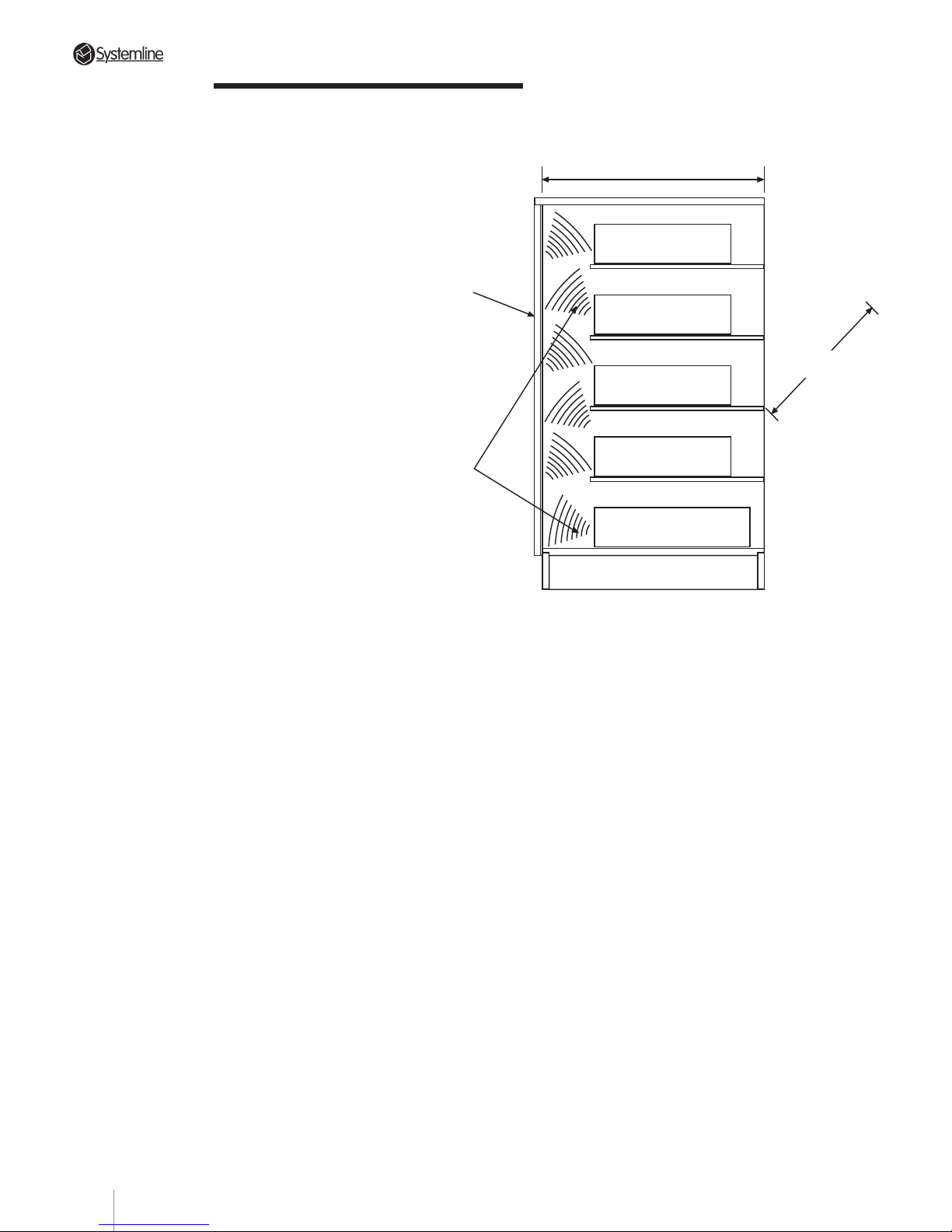
The S4.3 Controller is designed to
complement high quality home
entertainment components cosmetically.
Place it on a stable surface
in an equipment rack or
cabinet. Note that the S4.3
Controller is slightly deeper than most
sources (tuners, CD players, cassette
decks, etc.) and should not generally
be placed on top of these units.
The exact location may be governed
by existing wiring such as
Satellite or TV points, or
be determined by the
location of the existing
Hi-Fi system in which
case the central location point will
probably be in the lounge or family room.
Alternatively, if the Multi-room System is
to operate separately from (or instead of)
the main Hi-Fi system, the central location
point could be anywhere - hidden in a
cabinet in the hall or even under the
staircase - the only access required is to
change discs or tapes. See also Section 3.4
(Recommended A/V Wiring).
IMPORTANT
The S4.3 Controller contains 4
stereo power amplifiers which can
generate significant amounts of
heat. It is therefore necessary to
ensure that the controller is located
in an area where there is adequate
ventilation. Under no circumstances
should the ventilation slots at the
top and rear of the unit be
obstructed. If the S4.3 Controller is
mounted in a cabinet, ensure that
cool air can circulate when the doors
are closed. Ventilation slots/holes
should be provided at the top and
bottom of the cabinet.
Section 3 • System Planning
Minimum internal depth 500 mm
Tuner
C.D.
Tape
Optional Main
Amplifier
Super Controller
Minimum internal
width 450 mm
Doors
Infra-Red
Beam
Cut-away of equipment cabinet
The S4.3 Controller can also be mounted
on an open shelf - see Section 3.23.
3.22 Connections:
Make sure that you have enough room to
run all the connecting cables and dress
them appropriately behind the S4.3
Controller. Although each connection is
fully explained in the following sections
of this manual, take a quick glance
through the following list of possibilities
and decide how much space you will
need. Also remember that these cables
will make the S4.3 Controller much more
difficult to move when they are
connected. Plan accordingly.
a) Four pairs of PHONO to PHONO
interconnects – one from each source.
b) Four more pairs of PHONO to PHONO
interconnect cables – one each to the
appropriate input of the main system’s
preamplifier, etc., from the corresponding
“loop through” output on the S4.3
Controller (These will not be needed if
the S4.3 Controller is used as a standalone controller).
7
Page 11
PAGE
Section 3 • System Planning
c) Up to eight QED speaker cable pairs (two
for each zone) terminated with quick-fit
plugs.
d) Four six-conductor (+shield and drain)
CAT-5 data cables, each terminated with
the proper IDC connector.
NOTE: CAT-5 cables normally have eight
conductors, six of which can be used for
Systemline.
e) One shielded PHONO to PHONO
interconnect for RC-5 remote control code
connection (if required).
f) Up to four pairs of PHONO to PHONO
interconnects to power amplifiers from
the corresponding zone’s “Pre-out”
terminals (if required).
g) Up to four IR window emitters for
connection to the S4.3 Controller's TX
Infra-red outputs (if required).
h) Additional PHONO to PHONO shielded
cables and loudspeaker connections as
required for systems using more than one
S4.3 Controller amplifier.
i) Up to six “TX-FORMAT” terminal block
jumper wires when cascading multiple
S4.3 Controllers.
j) 3.5 mm to 3.5 mm stereo jack lead. Only
the top and middle ring of each jack
should be connected. This lead is used
when a.c. mains outlet control is required
from multiple controllers. Connection of
this link also enables all zones to be
turned off from any zone on any
controller.
We STRONGLY RECOMMEND that you
attach a tag or strip to each cable and
wire that permanently and positively
identifies it. This will help in any required
troubleshooting immediately after the
installation as well as make future service
calls or system add-ons much less
frustrating.
Avoid vague identifiers (“Tape Deck,” for
example) in favour of carefully defined
lines such as “To Input 3 from tape deck.”
However well you remember each
installation just after completing it, you
WILL FORGET by the next time you see it.
3.23 IR “Flood” Emitter
The S4.3 Controller has a high intensity
front panel IR “flood” emitter designed to
transmit commands from the remote
zones to the appropriate source
component. Although exact performance
will vary, this high power transmitter has
an effective operating range of
approximately 6m under normal
conditions.
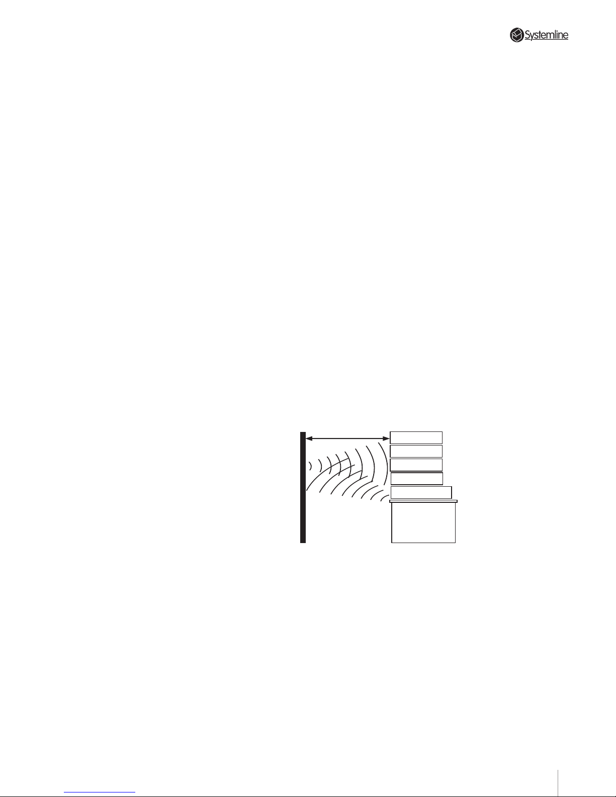
If the S4.3 Controller is on an open shelf,
the emitter’s signal must first travel to an
IR-reflective surface (an opposing wall, for
example) and then to the source
component.
WARNING:
It is very important that the Flood
Infra Red output does not reach any
DMS modules. If this happens the
system will not perform correctly. Do
not forget that Infra red can be
reflected by walls and doors into
other rooms. If you suspect that this
may be happening disconnect the
wire link between terminals 2 & 3 of
the TX format connector and
connect stick-on IR emitters as
described in section 3.24.
6 metres or less
Tuner
Tape Deck
CD Player
A/V Source
Super Controller
Keep total IR signal travel to 12m or less. Remember that it
must travel to a hard reflective surface and then back again.
3.24 IR Emitter Jacks & Cabling
Remember that the S4.3 Controller also has
four rear panel IR output jacks for use with
IR window emitters. Use these where
output from the front panel “flood” IR
emitter is blocked from the source
components by a door , full depth shelf, etc.
3.25 N/C Jack
This PHONO connector , located just to the
left of the RC-5 output, is unused at present.
8
Page 12

PAGE
3.34 Zone Splitters
Zone splitters allow you to divide any zone
into two separate areas. The Zone Splitter
acts as a remote speaker switch, controlled
by a DMS module within the zone, and
directs a chosen source input to either or
both sets of speakers.
To split a zone, a second set of speakers
and a Zone Splitter unit are required.
The following points must be considered
when planning and installing a Zone
Splitter system:
• The Zone Splitter is a parallel speaker
switching device. Therefore, speakers with
8 ohm impedance MUST be used in both
areas A and B.
• Only ONE Zone Splitter per zone may be
used.
• When a Zone Splitter is used, both pairs of
speakers will share the same volume level
and source.
• The switching of the speakers requires a
DMS module to be located in one of the
split zone areas.
Section 3 • System Planning
3.3 Zone Configuration
3.31 Basic Zone Complement
Each remote zone includes at least one
control code generator and a pair of
loudspeakers.
3.32 Control Code Generators
The code generator may be an RHS hand
held remote and a DMS module
combination. It can also be a stand-alone
KMS keypad. Details are in Sections 6.2
(RHS Hand-held Remote Control) and 6.3
(KMS Keypad).
Remember that the DMS module also
provides visual clues to total system
operation. Details are found in Sections
5.23 (Set-up Sequence) and 6.41
(Overview).
Most zones will use multiple control code
generators with the combination of one
DMS module and one KMS keypad being
the most common.
Mounting both the DMS module and
keypad in one double-width wall box
carries several advantages:
a) It simplifies the installation - all control
cables run to a single location.
b) It focuses the user on one location - he or
she either walks to the keypad or aims the
hand held remote at the wall-plate.
The DMS module reads infra-red signals
generated by the RHS hand-held remote
and, after translating them into a digital
code that is highly resistant to interference,
sends them to the S4.3 Controller . The KMS
simply translates key pushes into digital
code before sending them to the S4.3
Controller .
3.33 Loudspeakers
These will vary with installation
requirements and user expectations. The
S4.3 Controller’ s amplifier sections are
optimized for impedance loads of 4 ohms
or higher.
Systemline Hi-Fi standard ceiling speakers
are an obvious choice; please ask for
details.
9
Page 13
PAGE
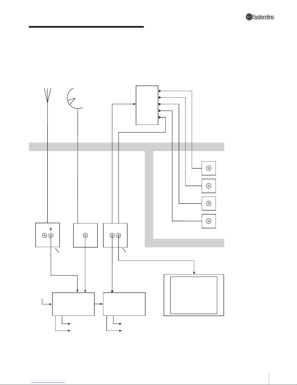
3.4 A/V Wiring
3.41 Recomended Wiring Configuration For
VCR, Satellite and Cable Distribution.
R.F.
T.V./F.M. Aerial
Satellite Dish
R.F.
Distribution
Amplifier
Kitchen
Bed 1
Family
Bed 2
Etc.
T.V.
Vid
SatF.M.
Padded
double socket
Non padded
double socket
Satellite Receiver
Video Recorder
Stereo audio
to Input 3 of
Controller
Stereo audio
to Input 4 of
Controller
T.V.
75 Ohm Co-ax
75 Ohm Co-ax
75 Ohm Co-ax
Satellite cable CT100
Cable
Section 3 • System Planning
10
Page 14
PAGE
Section 4 • Installation Guide
4.1 The S4.3 Controller
NOTE: Some configuration and set-up
options may require removal of the top
cover of the S4.3 Controller. Before
installing the S4.3 Controller, refer to:
- Section 5.22 Optional Operating Modes
- Section 5.51 Paging Inhibit
- Section 5.6 Configuring the Pre-Out
Sockets
and carry out any necessary internal
setting or adjustments.
Disconnect the mains supply to the
Controller before removing the top cover.
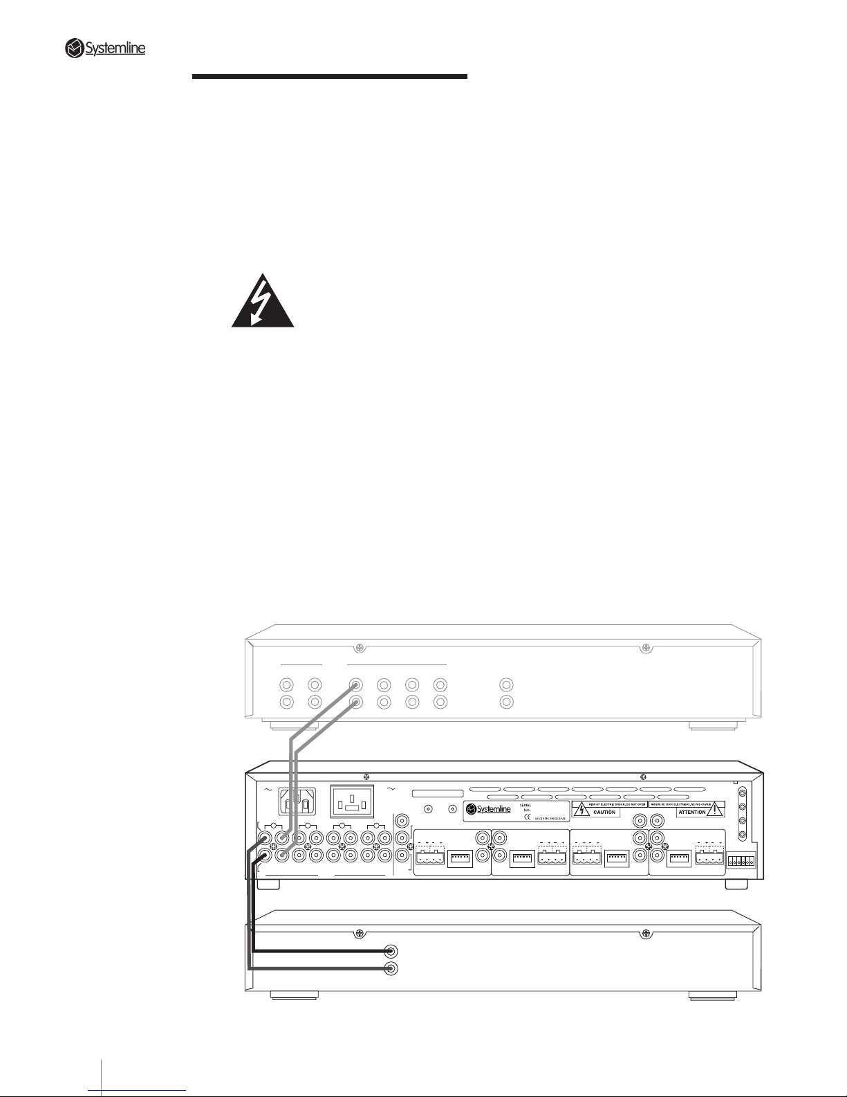
4.11 Source Connections
Connect LINE LEVEL sources (CD player,
tuner, etc.) to the S4.3 Controller’s rear
panel as follows.
a) Using shielded PHONO to PHONO cables,
connect the source’s output to the
corresponding input on the S4.3
Controller as detailed in the following
table:
Tuner
➠
Input 1
CD player
➠
Input 2
Tape Deck/Sat. Receiver/
Cable
➠
Input 3
DVD/VCR/CD 2/Tuner 2
➠
Input 4
Be sure to observe correct channel
continuity from source to S4.3 Controller.
The S4.3 Controller’s PHONO inputs are
labelled for easy identification with Left
Channel connections on the top row and
Right Channel connections on the bottom
row.
NOTE 1: The S4.3 Controller does not
accept a phono cartridge’s output
directly. If required, use a separate phono
preamp (such as QED Discsaver) to boost
the phono signal to line level.
NOTE 2: To simplify system operation,
we strongly suggest using only FIXED
LEVEL source outputs to the S4.3
Controller. If no FIXED LEVEL outputs are
available, use variable outputs but make
sure that the source component’s level
control is turned up sufficiently but not
so high as to overload the S4.3
Controller’s inputs.
TUNER CD AUX1 AUX2
INPUTSTAPE MONITOR
IN OUT LINE OUT
OUTPUT
RIGHT
LEFT
PREAMPLIFIER
TUNER
Tuner connected to Source 1 input with optional pass-through to preamp for shared use with separate system.
4
3
2
DATA
DATA
RC-5
N/C
AUDIO IN
AUDIO
OUT
IN
RIGHT
INPUTS
LEFT
OUT IN
OUT
IN
OUT
IN OUT
ZONE B
SPEAKERS
RIGHTLEFT
DATA
ZONE C
WE1
WE2
WE3
WE4
TX-FORMAT
ZONE A
SPEAKERS
RIGHT
LEFT
SPEAKERS
RIGHTLEFT
SPEAKERS
RIGHT
LEFT
DATA
T
X
O
U
T
P
U
T
S
1
ZONE D
S4.3 MUTI-ROOM
CONTROL
LINK
IN OUT
230V AC
50Hz
POWER CONSUMPTION: 430W MAX
PRE/LINE-OUTPRE/LINE-OUT
PRE/LINE-OUT
PRE/LINE-OUT
TRIGGER
PAGING
AC OUTLET
230V 50Hz
SWITCHED TOTAL:
460W MAX
123456
123456 123456 123456
123456
11
Page 15
PAGE
Section 4 • Installation Guide
b) If the source is shared by another system,
connect the appropriate S4.3 Controller
source output to the appropriate input of
the main system’s preamplifier, etc.
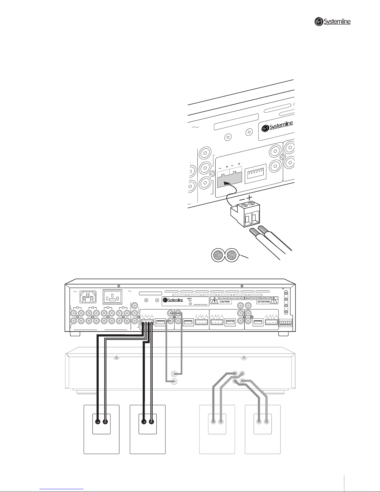
4.12 Speaker Cable Connections
NOTE: These zone connection
instructions deal with one zone only.
Connections for all other zones are
identical except for the mirror-image
connector placement on alternate zones.
Use the supplied quick-fit terminals for all
speaker cable connections.
Strip back each conductor's outer
insulation by 6mm, insert bare wire into
quick fit plug and secure using the screw
terminal fixing. Take care to ensure
proper polarity (note "+" is normally
identified by a fine rib running along one
edge).
BE CAREFUL AND BE PATIENT. This
is an admittedly tedious task,
particularly when you are hooking
up speakers for all four zones, but it
is essential for maximum system
enjoyment.
“Out of phase” loudspeaker hookups
(where one speaker in a stereo pair is
inadvertently connected “+” to “-” and
vice versa) may not be immediately
noticeable but will not be as pleasing in
the long term as a properly connected
stereo pair.
AUDIO IN
AUDIO
OUT
UT
SPEAKERS
RIGHTLEFT
DATA
Conforms to EN55013 & EN50082-1.
E.M.C. Test Certificate No. 300/95
ZONE D
S4.3 MUTI-ROOM CONT
R
CONTROL
LINK
IN OUT
PRE/LINE-OUT
TRIGGER
PAGING
A
C OUTLET
0V 50Hz
ITCHED TOTAL:
460W MAX
123456
Positive
Speaker cable
Quick fit plug
LINE IN
POWER
AMPLIFIER
SPEAKER
INPUTS
SPEAKER
INPUTS
4
3
2
DATA
DATA
RC-5
N/C
AUDIO IN
AUDIO
OUT
IN
RIGHT
INPUTS
LEFT
OUT IN
OUT
IN
OUT
IN OUT
ZONE B
SPEAKERS
RIGHTLEFT
DATA
ZONE C
WE1
WE2
WE3
WE4
TX-FORMAT
ZONE A
SPEAKERS
RIGHT
LEFT
SPEAKERS
RIGHTLEFT
SPEAKERS
RIGHT
LEFT
DATA
T
X
O
U
T
P
U
T
S
1
ZONE D
S4.3 MUTI-ROOM
CONTROL
LINK
IN OUT
230V AC
50Hz
POWER CONSUMPTION: 430W MAX
PRE/LINE-OUTPRE/LINE-OUT
PRE/LINE-OUT
PRE/LINE-OUT
TRIGGER
PAGING
AC OUTLET
230V 50Hz
SWITCHED TOTAL:
460W MAX
123456
123456 123456 123456
123456
SPEAKER
INPUTS
SPEAKER
INPUTS
SPEAKERS
Speaker outputs from one zone of the Super Controller. Also showing preamp output connections for use with
optional power amplifier.
12
Page 16
PAGE
The long runs from amplifier to speaker
typically found in multi-zone installations
demand heavy gauge, low resistance
speaker wire. Small diameter wire
reduces effective amplifier power and
adds substantial distortion to the audio
signal. Avoid problems by following
these minimum recommendations:
Under 20 m
➠
QED 42 STRAND
0.75mm2 (minimum)
More than 20 m
➠
QED QUDOS
2.5mm
2
Loudspeaker runs over 100m are
discouraged.
4.13 Preamp Outputs
Two PHONO jacks (Left and Right
Channel) labelled “Pre-out” provide line
level output controlled by the
corresponding zone command devices. If
a zone requires additional amplification,
use PHONO-PHONO shielded
interconnects from these outputs to a
separate power amplifier’s unbalanced
line inputs.
Each zone’s preamp output is fully
buffered and may be used either
independently or with the S4.3
Controller’s internal amplifiers to provide
additional flexibility for demanding
installations.
The Pre-amp output can also be
configured as a fixed level output,
independent of the zone’s volume level.
See Section 5.6 Configuring the Pre-Out
Sockets.
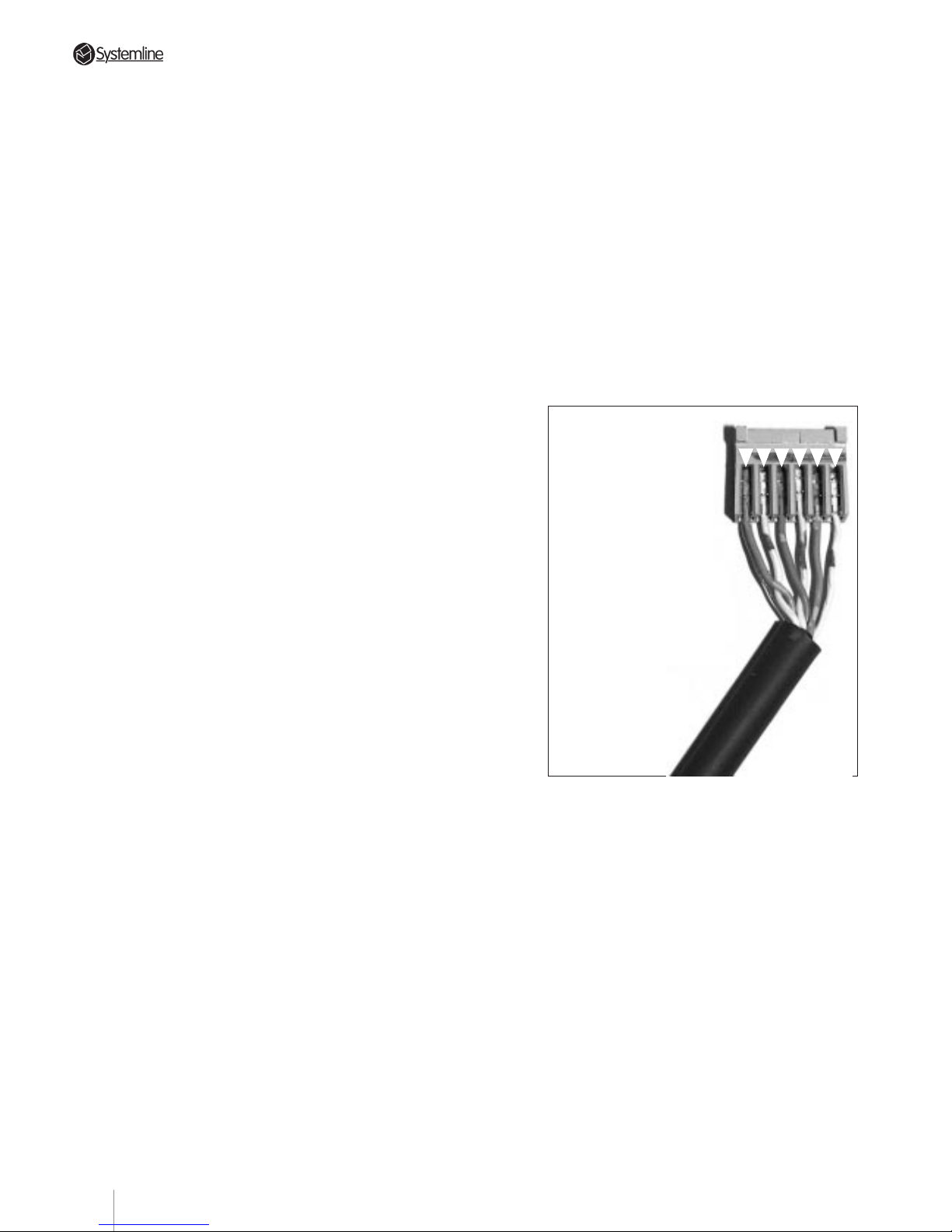
4.14 Data Cable Connections
Data communication to and from the S4.3
Controller and the remote zone’s DMS
module and KMS keypads is via 6conductor shielded cable. We recommend
QED CAT-5 FTP Systemline Cable.
(Note
that the IDC connectors only accept cable
with 26 awg conductors.)
We also recommend that you run each
zone’s data cable and speaker cables
together to save time. There is absolutely
no performance penalty for doing so.
The shield is absolutely essential in
maintaining data integrity over the long
runs between the controller/amplifier and
Section 4 • Installation Guide
Connectors for the DMS modules and KMS
keypads should be wired to follow the same
color coding.
The supplied IDC/Methode connectors need
to be 'crimped' to lock to the data cable’ s 26
gauge conductors. IDC tools are available
separately.
NOTE: Do not use a screwdriver , metal ruler
or knife blade to “crimp” these connections.
You may think these tools will work but you
will be mistaken. USE THE DEDICATED IDC
TOOL SPECIFICALL Y DESIGNED FOR THESE
CONNECTORS.
• Strip about 40 to 50 mm of the outer cable
insulation using a wire stripper, cutting pliers
or sharp knife.
a zone’s control code generating devices.
Make sure that the shield is firmly
connected at both the S4.3 Controller and
at any command device terminal.
NOTE: Only one data cable needs to run
from the S4.3 Controller to each zone.
Multiple DMS module and keypad
combinations in one zone should be
wired via series connections as detailed
in Section 4.3.
The maximum data cable length for
guaranteed operation is 100 m. Even
longer lengths may be practical in some
installations with low RF (Radio
Frequency) and EMI (Electro-magnetic
interference).
DATA CONNECTOR
WIRING CODE
Pin 1 • green & drain
Pin 2 •
white with green stripe
Pin 3 • Orange
Pin 4 • white with orange stripe
Pin 5 • blue
Pin 6 • white with blue stripe
Connections are made in
the same order at both ends
of the cables.
WARNING: ONLY USE
CORRECT IDC TOOL
(SL-IDC)
1 2 3 4 5 6
13
Page 17
PAGE
• Separate the foil screen from the
conductors and cut back to the level of
outer cable insulation.
•DO NOT strip insulation off the individual
conductors as the connector
automatically makes contact with the
conductor core when crimped.
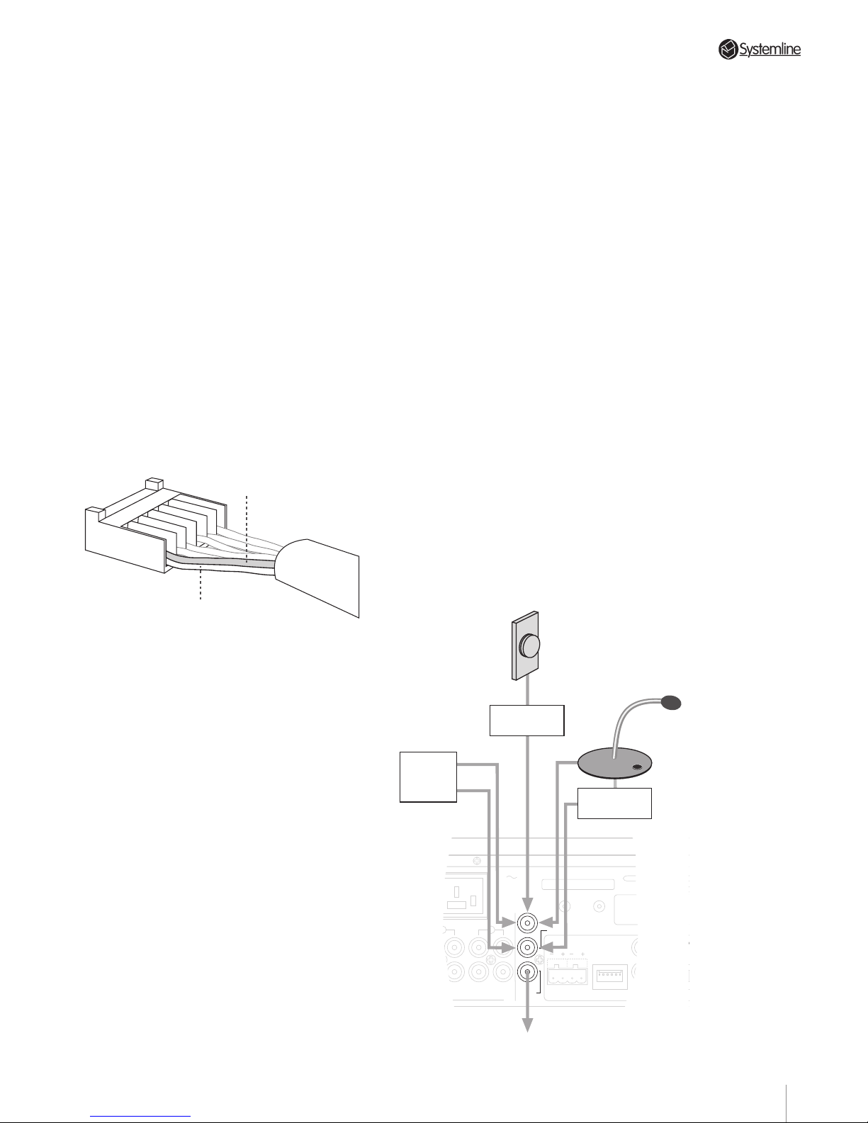
• Place the shield pig-tail into slot 1 (left hand
side) of the connector and press down
lightly
with the crimping tool to hold it in
place.
• Place the GREEN conductor
immediately on top of the bare drain wire
in slot 1, hold it in place and push down
harder with the crimping tool until you
hear a slight “click.” The drain and
green-insulated conductor should now be
locked into slot 1 (The clicking sound also
tells you that the connector slot contacts
have pierced the conductor’s insulation).
Test the connection by pulling gently on
both the drain and conductor.
Drain wire
connected to Pin 1
Green wire
connected to Pin 1
• Continue the process following the colour
code guide above until all other conductors
are locked in the appropriate connector
slots. Remember that slot 1 is the ONLY
ONE to hold both the shield and a
conductor. All other slots receive a single
conductor.
There will be two spare conductors if
using CAT-5 cable. These should be
folded back and secured to the cable
using insulating tape. These spare
conductors can then be used should other
conductors in the cable be damaged.
After attaching the cable conductors to the
connector, snap the connector on to the
appropriate zone’s 6-pin data ter minal on
the S4.3 Controller’s rear panel. Be careful
to centre the connector over the terminal
pins before inserting.
4.15 Paging Input
The paging input allows announcements to
be made over the system, or if required, for
zones to be muted: this may be useful
when used in conjunction with a door bell.
To function, the paging needs to be
activated from an external source. This can
be achieved via the 'Paging Trigger' phono
socket. Any device which shorts the trigger
input will cause the controller to enter its
paging mode.
NOTE: Under no circumstances should
external voltages be applied to the
paging trigger input. Should telephone or
door bell connections be required, QED
Bell-link and Tel-link interfaces should be
used.
The 'Paging Audio In' phono socket should
be connected to the audio output from the
announcement system (internal telephone
exchange/microphone amplifier).
An output can be taken from the 'Paging
Audio Out' socket if a second controller is
used or if an additional amplifier is
required.
NOTE: Only one audio source should be
connected to the Paging Audio input.
Section 4 • Installation Guide
IN
4
3
2
INPUTS
OUT
IN
OUT
IN OUT
SPEAKERS
RIGHTLEFT
DATA
ZONE D
S4.3 MUTI-ROOM
CONTROL
LINK
OUT
30W MAX
PRE
/
PRE/LINE-OUT
AC OUTLET
230V 50Hz
SWITCHED TOTAL:
460W MAX
123456
1
Door bell
Phone
Xchange
Trigger
Audio
Microphone
Amplifier
Trigger
AUDIO IN
TRIGGER
PAGING
AUDIO
OUT
Audio output to feed on to 2nd Controller
or to additional amplifier if required
QED Bell Link
(B-LK)
14
Page 18
PAGE
4.2 Zone Control Devices
4.21 DMS Module
PLACEMENT SUGGESTIONS: Exact
placement will vary with each installation
but we strongly recommend AGAINST
placement where the DMS will be
exposed to direct sunlight, powerful
fluorescent illumination or the output of a
high intensity spotlight, etc. These light
sources contain high levels of infrared
energy themselves and may cause
intermittent operation by saturating the
DMS.
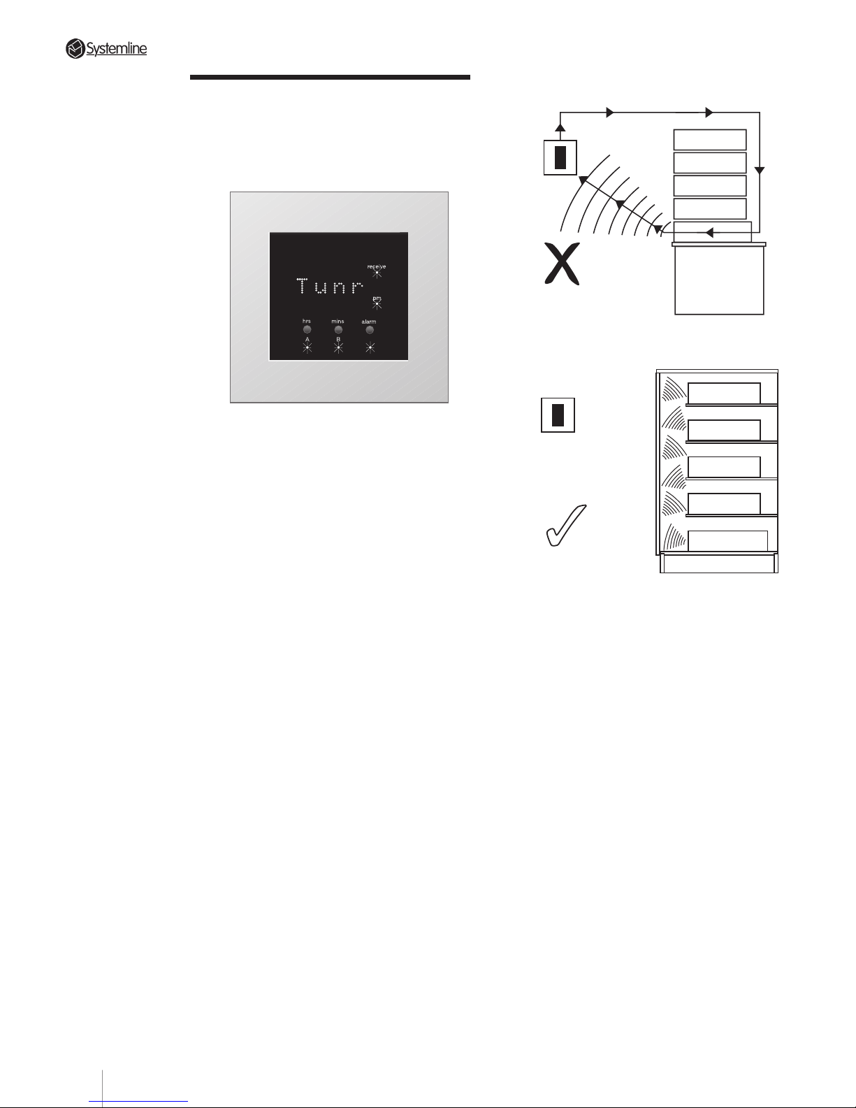
Also, avoid infrared “loops” by making
sure that a DMS module is
not
placed
where it might pick up signals from a
source component’s IR repeater or the
S4.3 Controller’s IR “flood” emitter.
Lastly, make sure that each DMS is on a
relatively uninterrupted “line-of-sight”
path to all likely locations from which the
hand held RHS remote might be used.
You’ll find the DMS/RHS combination
much less susceptible to signal
interference than other IR remote control
links but conservative planning will
ensure dependable operation under an
even wider variety of conditions.
Each DMS module has eight DIP switches
positioned centrally on the internal circuit
board and accessed by removing the
housing rear cover.
Section 4 • Installation Guide
Isolated operation
Lounge
Avoid Infra-red
continuous loops
Lounge
15
Page 19
PAGE
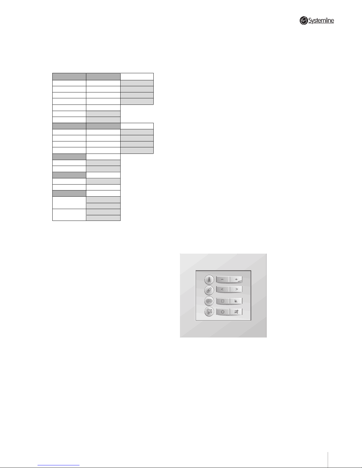
The DIP switches must be set on every
DMS module for the system to function
correctly. The following table shows the
available setting options for each switch:
Switch 1
OFF
OFF
ON
ON
Switch 3
OFF
ON
Switch 4
OFF
OFF
ON
ON
Switch 6
OFF
ON
Switch 7
OFF
ON
Switch 8
OFF
ON
Switch 2
OFF
ON
OFF
ON
Source 3
Tape
Sat
Switch 5
OFF
ON
OFF
ON
DMS is
Master
Slave
DMS reset
Default
Reset
Battery
Shipping
Position
Once
Installed
Address
Zone A
Zone B
Zone C
Zone D
Source 4
Dvd
Tun 2
Vcr
Cd 2
Zone Configuration. Select the required
zone for the DMS module by setting DIP
switches 1 and 2 as appropriate.
Component Source Configuration.
Sources 1 and 2 are set as standard to
tuner and CD respectively. Set DIP switch
3 as appropriate to configure source 3 as
a tape deck or satellite/cable. Set DIP
switches 4 and 5 as appropriate to
configure source 4 as a Dvd, Vcr, Cd 2 or
Tun 2.
Master / Slave Configuration. In all zones
where DMS modules are fitted, ONE DMS
module must be set as a MASTER (DIP
switch 6 = OFF) and all others set as
slaves (DIP switch 6 = ON). The MASTER
should be the first module in the serial
connection sequence, i.e. the one nearest
to the controller.
Internal Battery. Each DMS module
contains a rechargeable battery which
maintains the clock and other
configuration information when power to
the Controller is switched off. The battery
must be enabled during DMS installation.
Section 4 • Installation Guide
When fully charged, the battery will
maintain the stored information for
several weeks without recharging.
To enable the battery, set DIP switch 8 to
ON.
NOTE 1: After the display configuration
has been changed, DIP switch 7 must be
set to ON and then returned to OFF to
reset the system.
NOTE 2: After installation, leave the
Controller on continuously for afew days
to ensure that the internal battery is fully
charged.
4.22 The KMS Keypad
a) There are no restrictions on where the
KMS can be located. Common sense and
user convenience should be the
determining factors. Avoid using the
keypad in damp environments e.g.
bathroom. If the keypad needs to be
mounted externally a waterproof
enclosure should be used. These are
available from QED.
b) KMSs do not need to be set for particular
zones as they do not display zone or
system status information.
16
Page 20
PAGE
Section 4 • Installation Guide
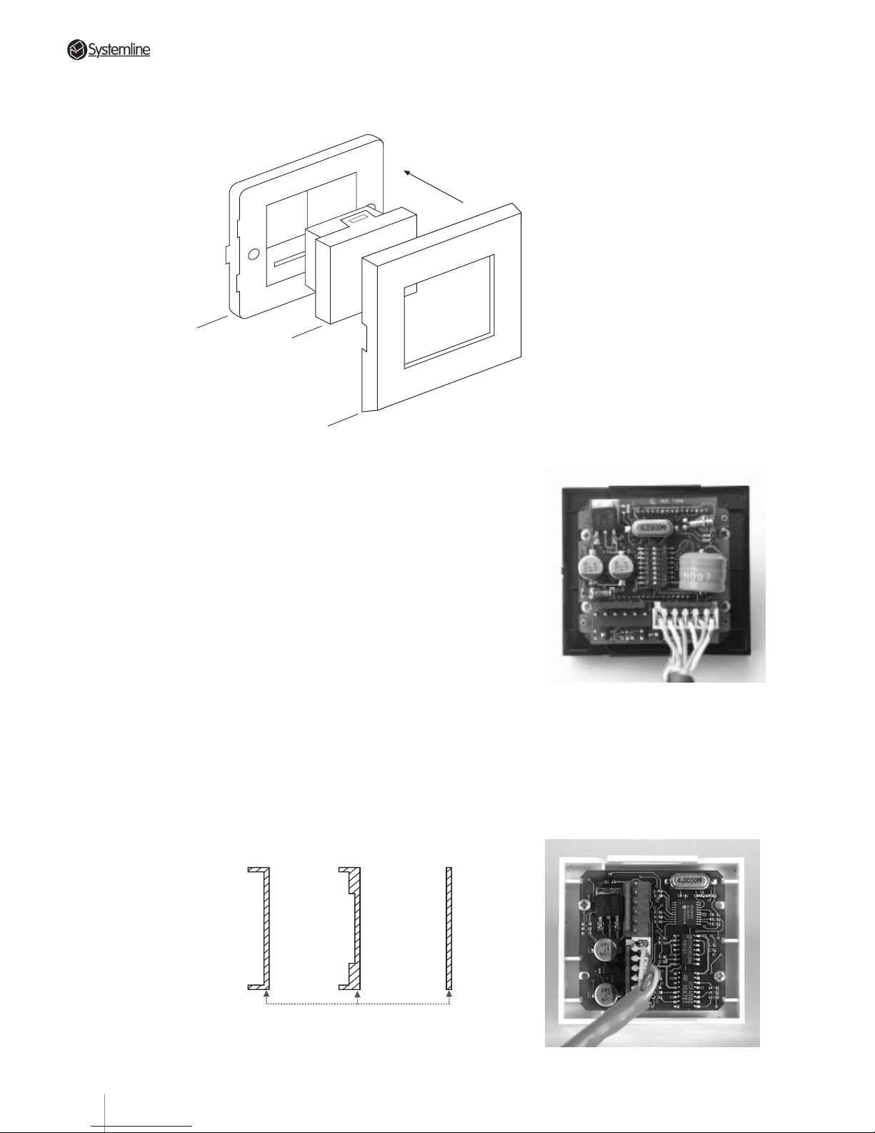
Most conventional “lipped” plates (T ype 1)
sit comfortably over the grey mounting
plate, secured simply by fitting the
mounting screws in the conventional way.
Type 2 plates requir e the mounting frame
to be milled to fit. Suitable guideline milling
drawings are available on request.
Type 3 plates are completely flush and
therefore require the grey mounting frame
to be inset into the back box. Suitable
frames are available to special order.
Connecting Modules. Data cable
terminations and connections are made
in the same way as previously detailed in
Section 4.14. Note that each DMS has two
data terminals (labelled IN and OUT)
located horizontally at the rear of the
module and the KMS has two data
terminals (labelled IN and OUT) located
vertically at the rear of the module.
Remember that a DMS module connected
to the zone A data cable terminal MUST
be used for initial set-up, particularly in
systems where non-RC5 source
components are included. Details will be
found in Section 5.23.
4.23 Fitting DMS & KMS Modules
into Back Box & Wall Plates
1) Clip module into grey mounting frame, as
shown.
2) Make all necessary wire connections to
module.
3) Screw in to wall box.
4) Clip on System 45* facia plate.
*System 45 and Sistema 45 are trade marks of
Hamilton Ltd. England and Ave Spa Italy
respectively. Alternative versions of
mounting plates and facias are available to
fit a wide variety of mainland European
back-boxes including the round type please ask your distributor for details.
A very wide variety of System 45 facias are
available in numerous colours and finishes,
but should you wish to use non-System 45
facias, you will first need determine the
category of the type of plates you wish to
use.
TYPE 1 TYPE 2 TYPE 3
CROSS SECTIONS
Grey mounting
frame
Module
System 45
range facia
Rear View of DMS
Rear View of KMS
17
Page 21
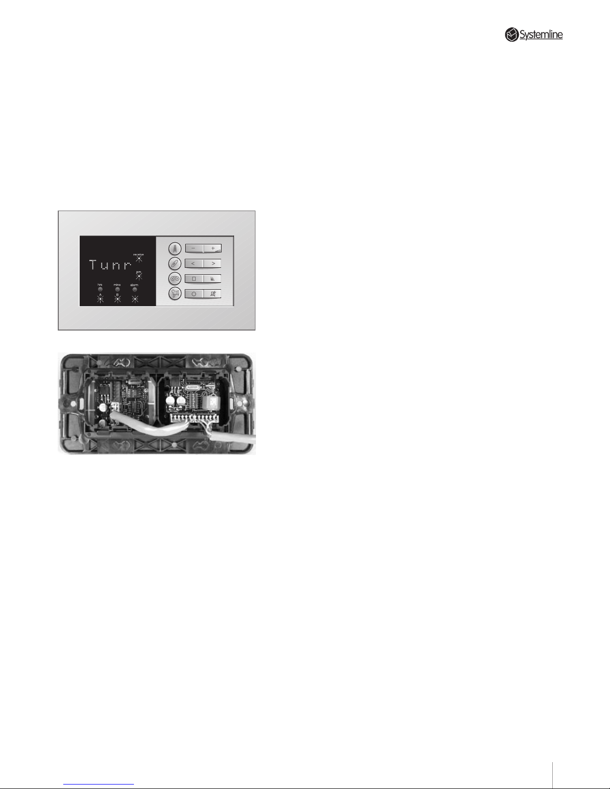
PAGE
Mounting a DMS and KMS module in a
double-width wall box is the most sensible
arrangement from an installation viewpoint
(fewer cable runs) but may not be practical
in all rooms.
NOTE: When installing a DMS and KMS
together in a double width wall box, the
only wiring required is a single link cable
to join the two modules and a single
cable to the Controller. This prevents any
danger of a cable jam behind the units.
Section 4 • Installation Guide
18
Page 22
PAGE
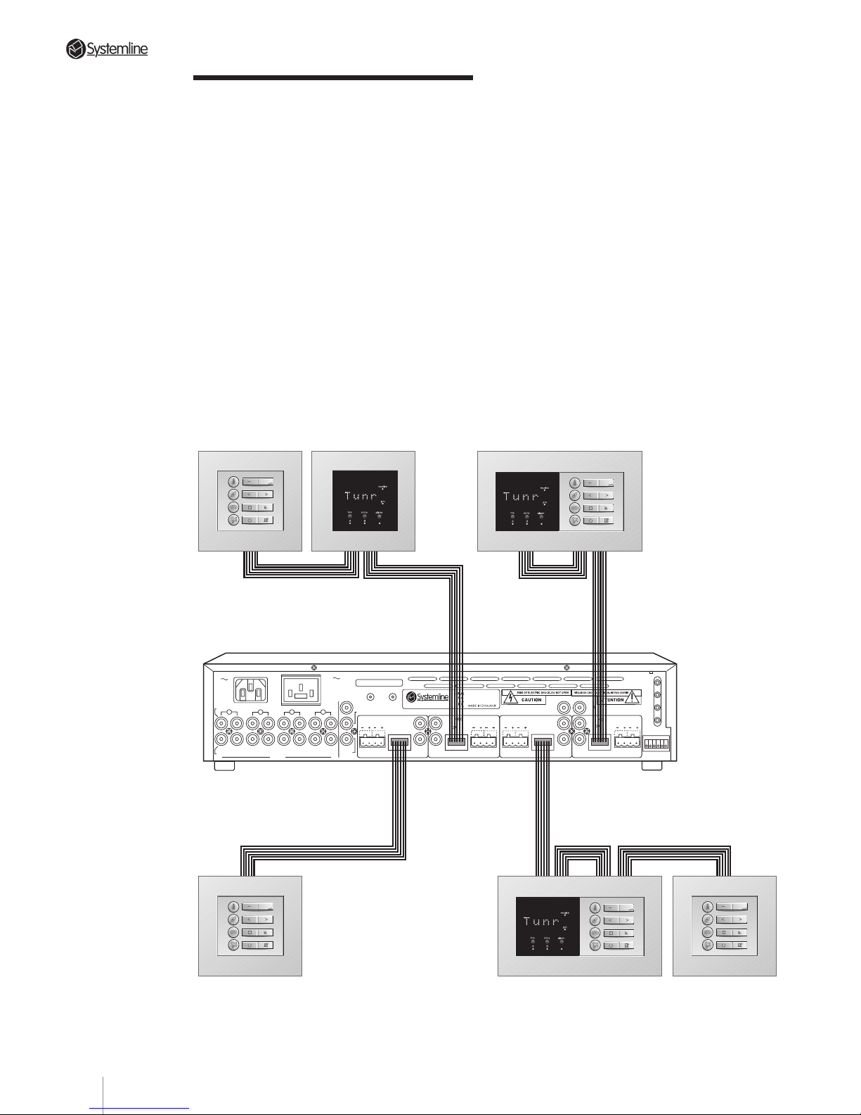
4.3 Zone Connection
Strategies
a) Each zone will support two DMSs and
three KMSs. All the command devices for
one zone should connect to each other in
serial fashion using their appropriate
circuit board-mounted “In” and “Out”
terminals.
b) Each DMS signals when it receives and
processes a command. This happens
regardless of whether the command was
generated by a keypad or a hand held
remote. However, a keypad located
“downstream” of a DMS module will
not
trigger that sensor’s command
processing indicator.
Whenever possible, we suggest that you
always wire a DMS/KMS double wall box
so that the DMS is located “downstream”
from the adjacent KMS (i.e., between the
KMS and the S4.3 Controller). This
ensures that the DMS module always
signals the user when the adjacent
keypad is used.
Whenever possible, we suggest that you
configure each combined DMS and
keypad module, with the 'Out' of the
keypad connecting to the 'In' on the DMS.
Section 4 • Installation Guide
4
3
2
DATA
DATA
RC-5
N/C
AUDIO IN
AUDIO
OUT
IN
RIGHT
INPUTS
LEFT
OUT IN
OUT
IN
OUT
IN OUT
ZONE B
SPEAKERS
RIGHTLEFT
DATA
ZONE C
WE1
WE2
WE3
WE4
TX-FORMAT
ZONE A
SPEAKERS
RIGHT
LEFT
SPEAKERS
RIGHTLEFT
SPEAKERS
RIGHT
LEFT
DATA
T
X
O
U
T
P
U
T
S
1
ZONE D
S4.3 MUTI-ROOM CONTROLLER
CONTROL
LINK
IN OUT
230V AC
50Hz
POWER CONSUMPTION: 430W MAX
PRE/LINE-OUTPRE/LINE-OUT
PRE/LINE-OUT
PRE/LINE-OUT
TRIGGER
PAGING
AC OUTLET
230V 50Hz
SWITCHED TOTAL:
460W MAX
123456
123456 123456 123456
123456
OUT
OUTOUT
OUT
IN OUT IN
OUT
IN
OUT
IN
OUT
19
Page 23
PAGE
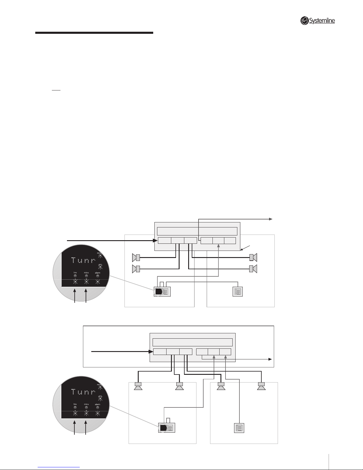
4.4 Splitting a Zone
A separately available product called a
Zone Splitter may be used to add a second
pair of speakers to a zone. This enables a
zone to be “split” between two rooms or
areas. Control of both the “prime” zone
and the sub-zone is via the DMS - see
Section 6.46 Zone Splitter Control for
further details.
The Zone Splitter is essentially a remote
control speaker switch and as such,
requires the speaker output and data cables
to be connected to it. The two pairs of
speakers and the data wires from the prime
and sub-zone are also connected to the
Zone Splitter - see diagrams below.
The sub-zone may be fitted with either a
KMS, a DMS or both. It could also be fitted
with a QED Speaker Volume Control (in line
with the speaker cables) or indeed, no
control at all. All speaker selections,
however, can only be carried out from the
prime zone DMS.
The following points must be considered
when installing a Zone Splitter system:
• Important: The Zone Splitter is a parallel
speaker switching device. Therefore,
speakers with 8 ohm impedance MUST be
used in both areas A and B.
T wo-way Quick-Fit speaker plugs (supplied)
must be used for speaker wiring and I.D.C.
plugs (supplied) for data wiring. These are
identical to those used on the S4.3
Controller - see sections 4.12 and 4.14.
• The Zone Splitter can be installed
anywhere but you must be able to connect
the cables from each pair of speakers
directly to the unit.
• There is no requirement for a power
connection to the Zone Splitter; the supply
is taken from the data cable.
Control of the Zone Splitter is described in
Section 6.46.
Section 4 • Installation Guide
DATA
TO CONTROLLER
ZONE SPEAKER
OUTPUT
L R
MAIN ZONE
SPEAKERS
L R
MAIN
DMS/KMS
SUB
DMS/KMS
SUB ZONE
SPEAKERS
L R
DATA
TO CONTROLLER
ZONE SPEAKER
OUTPUT
L R
MAIN ZONE
SPEAKERS
L R
MAIN
DMS/KMS
SUB
DMS/KMS
SUB ZONE
SPEAKERS
L R
DMS featuring split zone
switches & LED indicators
Prime
Zone
(A)
Sub
Zone
(B)
Prime Zone (A)
Selected
Sub Zone (B)
Selected
ZONE SPLITTER
Speaker outputs from Controller
Data wiring from Controller
Direct sub
zone data
DMS featuring split zone
switches & LED indicators
Speaker outputs from Controller
Data wiring
from Controller
Central location
ZONE SPLITTER
Prime
Zone
(A)
Sub
Zone
(B)
Prime Zone (A)
Selected
Sub Zone (B)
Selected
OUT IN OUT
OUT
OUT
a) 'Local' positioning of Zone Splitter
(Daisy Chain Connection)
b) 'Central' positioning of Zone Splitter (Star wired connection)
20
Page 24

PAGE
5.1 A.C. Line Considerations
5.11 A.C. for the S4.3 Controller
Connect the S4.3 Controller to an unswitched
a.c. source only.
5.12 A.C. for Source Components
At the rear of the S4.3 Controller is a switched
a.c. mains outlet. This can be used to power
source components in installations where the
user wants to power down source
components from a remote zone.
Switched a.c. outlet: When the front panel
switch of the S4.3 Controller is Off, the
switched a.c. outlet is also off. When the front
panel switch is turned On (i.e., when the S4.3
Controller first powers up to “Standby”
mode), the switched outlet remains off until
the S4.3 Controller receives a zone activation
command.
The switched a.c. outlet then remains on until
the front panel power switch is turned Off or
the S4.3 Controller receives a “power down”
command from a remote zone (STBY
command sent for >3 seconds).
5.13 Multi-Controller Control Link
In a multi-controller system, the Control Link
enables the control of all S4.3 Controller
switched a.c. outlets from any zone on any
controller. It is also possible to tur n all zones
off from a single zone on any controller when
this link is in place.
Each controller has two 3.5 mm sockets
marked CONTROL LINK IN and CONTROL
LINK OUT on the back panel. T o enable the
enhanced a.c. link, connect the CONTROL
LINK OUT socket on the first controller to the
CONTROL LINK IN socket on the second unit.
If appropriate, connect controllers 2 and 3 in
the same way.
CAUTION
T o interconnect CONTROL LINK IN and
CONTROL LINK OUT sockets, either obtain a
STEREO 3.5 mm jack plug interconnect lead
from QED or make up suitable leads.
If making up leads, DO NOT USE MONO
LEADS OR PLUGS. Only the TIP and INNER
RING of the stereo jack plugs should be
connected - DO NOT connect the OUTER
ground/earth.
5.14 External Control of Switched
A.C. Mains Outlets.
When external control of the a.c. outlet is
required, connect terminal 6 of the TX
FORMAT connector on the back panel to
terminal 1 (ground). In a multi-controller
system, terminal 6 of the TX FORMA T
connector on each controller must be daisy
chained using suitable hook up wire to enable
full remote control of a.c. switching.
If the pins 1 and 6 are shorted, all controller
a.c. outlets are switched On permanently and
the “power down” command has no effect. If
the external control signal to terminal 6 is
switched Off, the a.c. outlet(s) will be turned
Off unless any zone of any controller is On. In
this case, the a.c. outlet(s) will remain on.
5.15 A.C. Power Recommendations
a) When using the switched mains a.c. outlet to
supply source components it is
recommended that a mains distribution unit
be used with the IEC plug supplied.
b) Ensure that the total power consumption of
all the source components connected to each
switched a.c. outlet does NOT exceed 400W.
c) Power amplifiers are not suitable for
connecting directly to the controller's
switched a.c. mains outlet.
d) Source components featuring a standby
mode i.e. a soft toggle Power On/Off button
should not be used with the switched
controller a.c. mains outlet.
5.2 Source Component Setup
NOTE: Equipment manufacturers change
their remote control systems from time to
time. It is therefore advisable to check the
operation of a source component with the
S4.3 Controller before specifying.
If you encounter any compatibility problems
with the supported components listed in 5.22,
please notify QED using the FAXBACK page
in this manual. This will enable us to check
that you have the latest software, and also to
provide codes for these components in the
future.
Section 5 • System Set-up
21
Page 25
PAGE
Section 5 • System Set-up
5.21 Default Operating Mode
The codes for the programmable inputs to
the S4.3 Controller are stored on two code
banks or “pages” within the translator card as
detailed in 5.22 below. On delivery , the
controller is factory set with the Page 1 codes
available for use.
5.22 Optional Operating Modes
The S4.3 Controller supports a number of
equipment brands with the codes stored on
two code banks or “pages” as listed below.
T wo setup overlay cards (one for each page)
are supplied for use during source
component configuration.
If the available sources are all on Page 1, no
internal adjustment is required. If any or all
sources are on Page 2, the configuration of
the translator card must be changed by
altering the setting of the four miniature
switches which form switch SW1, as detailed
below..
As this requires removal of the top cover of
the controller, it is recommended that SW1 is
configured BEFORE installation of the
controller. Use a ballpoint pen or similar to
move each switch (Right = ON, Left = OFF).
WARNING
Disconnect the mains supply to the controller
before removing the top cover.
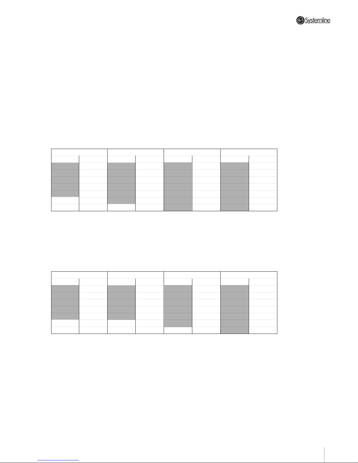
T o use a Sony tuner on Input 1, a Rotel CD
player on Input 2, a PACE satellite on Input 3
and a T oshiba DVD on Input 4 for example,
SW1 should be set as follows:
Switch 1 = ON
Code Input 1
ROTEL Tuner
ONKYO Tuner
TECHNICS Tuner
NAD Tuner
LUXMAN
ROTEL
ONKYO
TECHNICS
NAD
LUXMAN
ROTEL
ONKYO
TECHNICS
NAD
LUXMANTuner
Tape
Tape
Tape
Tape
GALAXY Satellite
JERROLD Cable Box
CD Player Tape
CD Player
CD Player
CD Player
CD Player
RC-5 Tuner 2
SONY Tuner 2
PIONEER Tuner 2
Tuner 2
TOSHIBA
YAMAHA
DVD
SONY CD Player
Code Input 2 Code Input 3 Code Input 4
Switch 2 = ON Switch 3 = ON Switch 4 = ON
Sony tuner on Page 1 SW1 switch 1 to OFF
Rotel CD on Page 2 SW1 switch 2 to ON
PACE satellite on Page 1 SW1 switch 3 to OFF
T oshiba DVD on Page 2 SW1 switch 4 to ON
NOTE: As can be seen from the Page 1 and
Page 2 tables, it is possible to use either two
CD players or two tuners as two of the source
components. However, the two components
MUST be different brands; i.e. Pioneer CD on
input 2 and a Panasonic CD on input 4.
Switch 1 = OFF
Code Input 1
RC-5 Tuner
SONY Tuner
PIONEER Tuner
YAMAHA Tuner
DENON Tuner
SONY Tape
PIONEER Tape
YAMAHA Tape
DENON Tape
PACE Satellite
NOKIA Satellite
RC-5 CD Player RC-5 Tape
SONY CD Player
PIONEER CD Player
YAMAHA CD Player
DENON CD Player
SONY Mini Disc
RC-5 Video
SONY*
*
SONY code 2
CD Player
PIONEER CD Player
PANASONIC
Video
SONY Video
PIONEER DVD
Code Input 2 Code Input 3 Code Input 4
Switch 2 = OFF Switch 3 = OFF Switch 4 = OFF
22
Page 26
PAGE
Section 5 • System Set-up
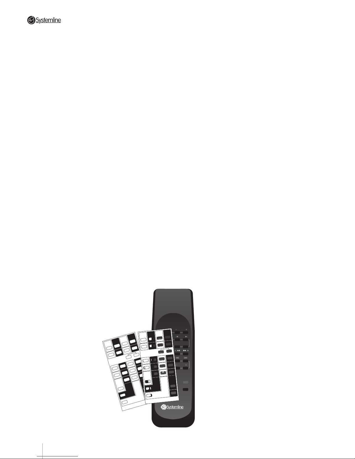
d) Place the appropriate Set-up Card over the
RHS’s pushbuttons.
e) With the RHS pointing at the DMS module,
enter “Set-up” mode by pressing the SetUp buttons (RANDOM and DISC buttons)
as indicated on the overlay card and
holding them depressed for a few seconds
until “Set?” is displayed. This indicates that
the system is ready to receive source set-up
information.
f) Push the desired command code button of
the input you want to set. You may select
any required combination of brands, but
remember:
• The appropriate switch within translator
card switch SW1 must be configured for
the code bank (page) holding the code for
the component for each input. Refer to
Section 5.22.
• for each input you must use the correct
overlay card for the configured code bank;
i.e. Card 1 for Page 1 and Card 2 for Page 2.
• if you are using two CD players or two
tuners, they must be different brands.
Zone A's DMS will display the following
characters to indicate your choice of
custom command configuration.
Bank 1 Bank 2
Set Up CardSet Up Card
A = RC-5 Tuner Rotel Tuner
B = RC-5 CD Rotel CD
C = RC-5 VCR RC-5 Tuner2
D = RC-5 Tape Rotel Tape
E = Sony Tuner Onkyo Tuner
F = Sony CD Onkyo CD
G = Sony CD2 Sony Tuner2
H = Sony Tape Onkyo T ape
I = Pioneer Tuner Technics Tuner
J = Pioneer CD Technics CD
K = Pioneer CD2 Pioneer T uner2
L = Pioneer Tape Technics Tape
M = Yamaha Tuner NAD T uner
N = Yamaha CD NAD CD
O = Panasonic VCR Yamaha Tuner2
P = Yamaha Tape NAD Tape
Q = Denon CD Luxman CD
R = Sony VCR Toshiba DVD
S = Denon Tape Luxman Tape
T = Denon Tuner Luxman Tuner
U = Sony MiniDisc No Code
V = Pace Sat Galaxy Sat
W = Pioneer DVD Sony2 CD2
X = Nokia Sat Jerrold Cable
5.23 Set-up Sequence
a) Refer to 5.22 above - Ensure that switch
SW1 on the S4.3 Controller translator card
has been re-configured as necessary if the
codes for any source components are
stored on code bank (page) 2.
b) Locate the DMS module for zone A.
Optional operating modes CANNOT be
changed from any other zone, or even from
zone A ’s (optional) keypad. To confirm that
the DMS is connected to zone A, send a
command with the RHS hand held remote
and monitor zone A ’s green Code LED on the
S4.3 Controller’ s front panel: it will flash
when the S4.3 Controller recognizes and
processes a command.
Ensure that the flood output is disconnected
(remove the link between pins 2 & 3 of the
TX format connector) if set-up is carried out
in the same room as the controller .
NOTE: Any DMS module can be connected
to the zone A data terminal for this
procedure. Even if zone A is equipped with
a wall mounted DMS module, it is probably
more convenient to temporarily disconnect
the data cable from that unit and substitute
another DMS placed near the S4.3
Controller and source components. Make
sure that any DMS used in this set-up
sequence has the circuit board DIP
switches set for zone A. (See Section 4.21
b) for details.)
c) Select any input (tuner, CD etc.) on the RHS
so that the corresponding indication shows
on zone A’s DMS
module.
TUNER
CD
FAV STN PRESETS
STOP SKIP
RANDOM DISC
TAPE/SAT STOP
VIDEO/LD
STOP
PAUSE CHNL
X
VOL
VOL
MUTE
STBY
E
ONKYO
F G
ONKYO
SONY-Tu2
H
ONKYO
I J K
L
TECHN
TECHN
PIO-Tu2 TECHN
M N O
P
NAD
NAD
YAM-Tu2 NAD
Q R
S
LUXMAN
TOSH-Dvd LUXMAN
T
LUXMAN
U
V
V
RCA-SAT
W
SONY2-Cd2
Tuner
A
ROTEL
Dvd
Cd2/Tu2
C
RC-5-Tu2
B
ROTEL
D
ROTEL
Sat
Tape
X
V
U
No Code GLX-Sat
JER-Cab
X
Cd
BANK 2 SET-UP CARD RHS3
PRESS BOTH BUTTONS
TOGETHER & HOLD TO
ENTER/EXIT SET-UP MODE
E
SONY
F G
SONY
SONY-Cd2
H
SONY
I J K
L
PIONEER
PIONEER
PIO-Cd2 PIONEER
M N O
P
YAMAHA
YAMAHA
PAN-Vcr YAMAHA
Q R
S
DENON
SONY-Vcr DENON
T
DENON
U
V
V
RCA-SAT
W
PIONEER-Dvd
Tuner
A
RC-5
Dvd
Vcr/Cd2
C
RC-5-Vcr
B
RC-5
D
RC-5
Sat
Tape
X
V
U
SONY-Md PACE-Sat
NOK-Sat
X
BANK 1 SET-UP CARD RHS3
Cd
PRESS BOTH BUTTONS
TOGETHER & HOLD TO
ENTER/EXIT SET-UP MODE
23
Page 27

PAGE
g) After selecting the desired command
codes for all the component categories
you wish to change, exit “Set-up” by
pressing the Set-Up buttons (RANDOM
and DISC buttons) as indicated on the
overlay card.
The DMS will display “Save” while
quitting set-up to indicate that the system
has stored chosen command codes and
exited the Set-up mode.
All changes are stored in non-volatile
memory and can not be accidentally
erased, even by unplugging the S4.3
Controller. The only way to change
command code operation is to access
Set-up mode again.
h) Once set-up has been completed the
controller must be turned off (using the
front panel power switch on the
controller) for 15 seconds and then on
again for the new settings to take effect.
For example, if you want to re-configure
the system to operate with a Pioneer CD
player and a Panasonic Video player,
simply:
1. Ensure that the appropriate switches
within switch SW1 on the controller
translator card are set correctly for the
components.
2. Use the correct overlay card for each
component.
3. Enter Set-up mode (“Set ?” will show on
the DMS).
4. Push the button marked “Pioneer” in the
C.D. Input column. ("J" will be shown on
the DMS)
5. Push the button marked “PANASONIC” in
the VCR/CD2/DVD input column.("O" will
be shown on the DMS)
6. Exit Set-up mode (“Save” will be
displayed on the DMS).
5.3 IR System and Control
Codes
5.31 Overview
The S4.3 Controller’s IR system provides
extensive remote control flexibility. With
the possible exception of the points in
Sections 5.32 and 5.33 below, nothing
needs to be done to set up the IR system.
However, please note the following
points:
a) The IR codes generated by the RHS hand
held remote are S4.3 Controller “system
specific” codes and ARE NOT the same
codes generated by a source component
controller, even for functions that appear
identical such as “CD play,” for example.
In other words, you can not use the RHS
to directly control a Marantz CD player
but must use it through a DMS module
from a remote zone. The S4.3 Controller
system does the following:
•A wall mounted DMS module receives
the remote’s code sequence and
translates it into proprietary 5 bit digital
code.
•This digital code travels over the data
cable to the S4.3 Controller.
•The translator card in the S4.3 Controller
restores the code’s original configuration
(when required) and sends it to both the
IR “flood” emitter and the rear panel IR
outputs for use by the appropriate source
component.
b) In addition to passing S4.3 Controller
system codes, the IR system will pass
ALMOST any IR code sequence from a
DMS to a source component. This allows
you to control equipment brands which
are not supported by the internal
translator card. (These few exceptions
use a non-standard IR transmission
frequency.)
Section 5 • System Set-up
24
Page 28
PAGE
Section 5 • System Set-up
5.32 Front Panel IR Flood Emitter
All S4.3 Controllers are shipped with the
front panel IR “flood” emitter engaged.
However, there may be applications
(system installations on open shelves in
very large, bright rooms, for example)
where the IR “flood” emitter might
interfere with proper source component
operation or will not be particularly
effective in communicating control
pulses.
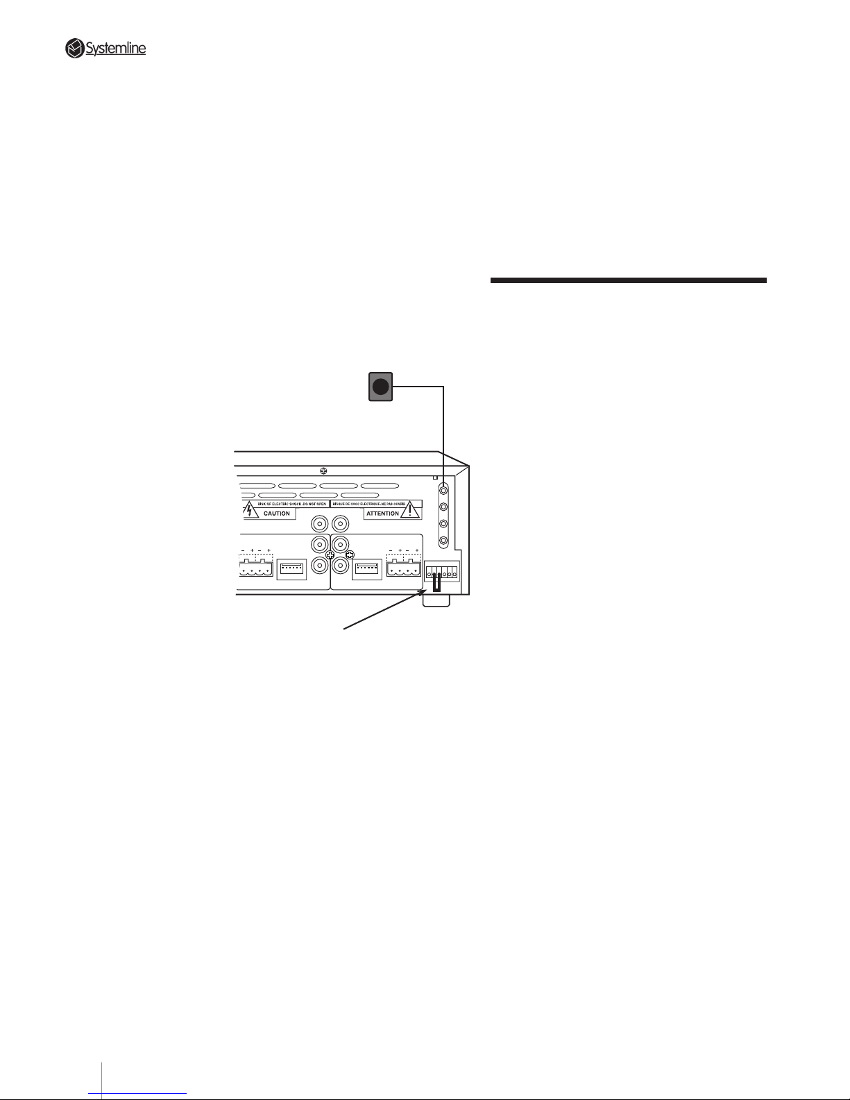
To disable the IR “flood” emitter, remove
the jumper wire between screws 2 and 3
of the TX FORMAT terminal block located
on the lower right hand side of the S4.3
Controller’s rear panel.
5.33 Rear Panel IR Emitters
The S4.3 Controller rear panel has four
paralleled 3.5 mm mini-jack sockets
labeled "TX OUTPUTS-WE". These accept
the QED window emitters (Order Code
RL-WE).
Use these optional IR window emitters in
situations where the S4.3 Controller is
located some distance away from the
source components or where the IR
“flood” emitter may have difficulty
transmitting reliable source control data.
• Each IR window emitter is fixed to the
front of the source component by means
of an adhesive. It is very important that
the window emitter is located over the IR
receiver of the source component
(normally behind an acrylic panel). If you
are unsure about the location of the
receiver, send a control code from a
keypad or RHS in a remote zone while
slowly moving the window emitter over
the front panel of the source component.
Once reliable operation is obtained note
the position and affix the window emitter.
NOTE: •The adhesive backing should be
removed whilst locating the receivers
“sweet spot”.
5.4 Advanced Multi-Zone
Systems
5.41 8 - and 12 - Zone Systems
The S4.3 Controller is designed to supply
independently controlled sound to four
separate zones. In many instances, a
complex system may require even more
flexibility. To satisfy these requirements,
typically two or three S4.3 Controllers
may be cascaded to form an 8 to 12
independent zone system. Under these
circumstances, all S4.3 Controllers can
still use only one set of source
components.
5.42 Large System Configuration
Should more than three controllers be
required, then this is possible provided
that care is taken to ensure that all
controllers are adequately supported and
ventilated. It is important to ensure that
no more than three controllers are
physically stacked on top of one another.
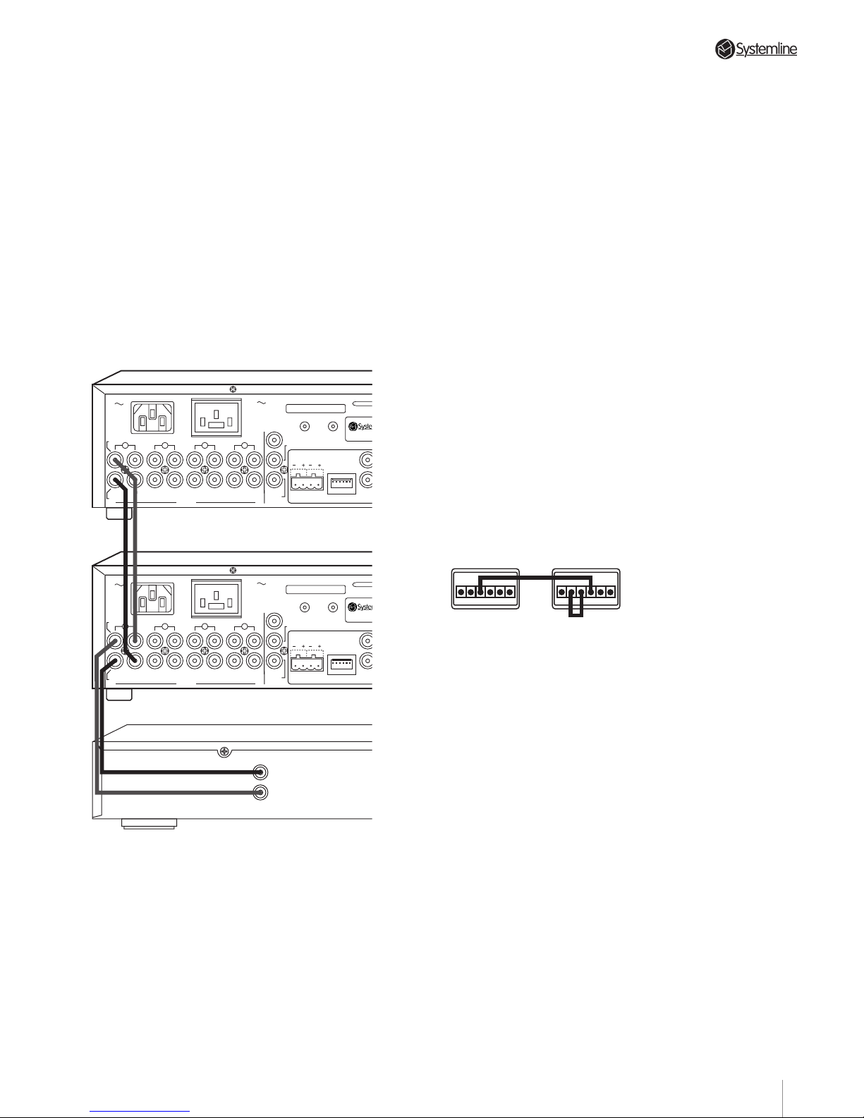
The following examples explain how two
or three S4.3 Controllers can be linked
together. The same principles apply for
larger systems employing more than
three Controllers.
All hookup instructions will assume that
zones 1-4 will be handled by the bottom
S4.3 Controller (“A”), zones 5-8 by the
S4.3 Controller immediately above it
(“B”) and zones 9-12 by the top unit
(“C”).
Remove this jumper to disable
front panel IR flood emitter.
Optional remote IR
emitters for use in lieu of
front panel IR flood emitter.
DATA
DATA
RC-5
N/C
ZONE B
WE1
WE2
WE3
WE4
TX-FORMAT
ZONE A
A
KERS
RIGHT
SPEAKERS
RIGHTLEFT
SPEAKERS
RIGHT
LEFT
T
X
O
U
T
P
U
T
S
PRE/LINE-OUTPRE/LINE-OUT
123456 123456
123456
25
Page 29
PAGE
Section 5 • System Set-up
Section 5 • System Setup
5.44 IR Flood Emitter Connections
When two or three S4.3 Controllers are
used in the same system, we recommend
that you connect them so that only one IR
“flood” emitter works. This avoids potential
interference that may lead to erratic
operation.
Use the following connection guide for
multiple S4.3 Controller systems:
a) For 5-8 zone systems (two S4.3
Controllers):
•Remove the jumper between terminals 2
and 3 of the TX FORMA T block on S4.3
Controller “A” but leave the jumper in
place on S4.3 Controller “B”.
•Connect terminal 3 of S4.3 Controller A ’s TX
FORMAT block to terminal 4 on S4.3
Controller “B”.
This completes the signal link to the IR
“flood” emitter on S4.3 Controller “B”.
TX-FORMAT
123456
TX-FORMAT
123456
Use this jumper arrangement in a system with 2 Super
Controllers to disable the flood IR emitters on the first
controller and enable the emitter on the second.
Super Controller
"A"
Super Controller
"B"
b) For 9-12 zone systems (3 S4.3
Controllers):
•Remove the jumpers between terminals 2
and 3 of the bottom two S4.3 Controller’s
TX FORM blocks (S4.3 Controller “A” and
“B”) but leave the jumper in place on
S4.3 Controller “C”.
•Connect terminal 3 of the S4.3 Controller
“A” TX FORM block to terminal 4 on S4.3
Controller “B”.
•Connect terminal 3 of the S4.3 Controller
“B” TX FORM block to terminal 4 on S4.3
Controller “C”.
This completes the signal link to the IR
“flood” emitter on S4.3 Controller “C”.
5.43 Source Connections
Connect all sources to the first S4.3
Controller (“A“) in accordance with the
instructions in Section 4.11. Connect
Source 1’s “loop through” outputs on S4.3
Controller “A” to the corresponding Source
1 inputs on S4.3 Controller “B“ using
shielded PHONO to PHONO cables. Follow
this procedure for all inputs.
The loop “OUT“ for each of the sources on
the last controller in the chain can be
connected to the main system amplifier's
inputs if required.
If a system requires a third S4.3 Controller,
simply repeat this procedure but connect
source outputs on S4.3 Controller “B” to
the corresponding inputs on S4.3
Controller “C”.
NOTE: It is particularly important to
observe proper channel continuity when
connecting source components to more
than one S4.3 Controller. Once again, BE
PATIENT AND BE CAREFUL.
OUTPUT
RIGHT
LEFT
4
3
2
AUDIO IN
AUDIO
OUT
IN
RIGHT
INPUTS
LEFT
OUT IN
OUT
IN
OUT
IN OUT
SPEAKERS
RIGHTLEFT
DATA
1
ZONE D
S4.3 MUTI-R
O
CONTROL
LINK
IN OUT
230V AC
50Hz
POWER CONSUMPTION: 430W MAX
PRE/LINE-OUT
TRIGGER
PAGING
AC OUTLET
230V 50Hz
SWITCHED TOTAL:
460W MAX
123456
Super Controller "B"
Super Controller "A"
Source component
4
3
2
AUDIO IN
AUDIO
OUT
IN
RIGHT
INPUTS
LEFT
OUT IN
OUT
IN
OUT
IN OUT
SPEAKERS
RIGHTLEFT
DATA
1
ZONE D
S4.3 MUTI-R
O
CONTROL
LINK
IN OUT
230V AC
50Hz
POWER CONSUMPTION: 430W MAX
PRE/LINE-OUT
TRIGGER
PAGING
AC OUTLET
230V 50Hz
SWITCHED TOTAL:
460W MAX
123456
26
Page 30
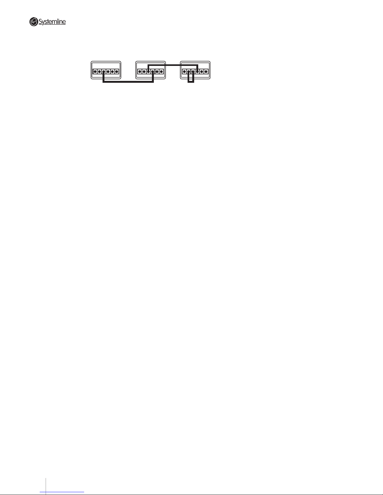
PAGE
5.48 A.C. Connections
In systems using multiple S4.3
Controllers, ensure that the controllers
are powered from a suitably rated mains
outlet. Ensure when using a mains
distribution unit that it has a high enough
capacity for the total number of
controllers and source components.
If you wish to control the a.c. mains
supply to the source components then
this is possible using the switched outlet
on each of the controllers. Each outlet has
a 460W capacity which must not be
exceeded. It is possible to connect all
source components to one controller
switched a.c. outlet if within the 460W
rating. Alternatively source components
can be connected to different switched
a.c. outlets in a multiple controller
installation provided that the Control Link
detailed in Section 5.13 is in place.
5.49 Engaged Operation
When a single S4.3 Controller is used, the
DMS module lets the user know when
two zones are listening to the same
source by changing the first character of
the source description from upper case to
lower case i.e. from “Cd” to “cd”.
This is a polite message to let the user
know that if they change tracks or skip
channels it will do so in two or more
zones.
When multiple controllers are used this
feature is still operational, but only
indicates the engaged status for the
zones connected to any one controller.
This means that a zone connected to
controller A and a zone connected to
controller B, listening to the same source,
will not indicate “engaged”.
TX-FORMAT
123456
TX-FORMAT
123456
TX-FORMAT
123456
Use this jumper arrangement in a system with 3 Super
Controllers to disable the flood IR emitters on the first
two Controllers and enable the emitter on the third.
Super Controller
"A"
Super Controller
"B"
Super Controller
"C"
5.45 IR Repeater Connections
Use the following connection guide for
multiple S4.3 Controller systems:
a) For 5-8 zone systems (two S4.3
Controllers): Connect all IR repeaters to
only S4.3 Controller “B”.
b) For 9-12 zone systems (three S4.3
Controllers): Connect all IR repeaters to
only S4.3 Controller “C”.
5.46 RC-5 Bus Connection
Some source components feature an “RC5” phono socket for sending and receiving
commands. If for example you wish to use
an RC-5 tuner it may not have its own IR
receiver. If this is the case then the only
way of sending commands to the tuner will
be via the RC-5 phono socket on its rear
panel. To connect the tuner to the controller
take a single phono lead and from the RC-5
socket on the controller to the RC-5 IN
socket on the tuner.
NOTE: The Audio lead must be
connected from the tuner to the
controller for this link to work.
5.47 IsoLink Connection
Some source brands such as Pioneer
feature an IR CONTROL BUS similar in
operation to the RC-5 Bus detailed in
section 5.46. QED can supply an optional
adapter called IsoLink which enables
equipment fitted with a suitable 3.5mm
Bus socket to be controlled via an IR TX
Output on the controller. All instructions
are supplied with the adapter.
Section 5 • System Set-up
27
Page 31
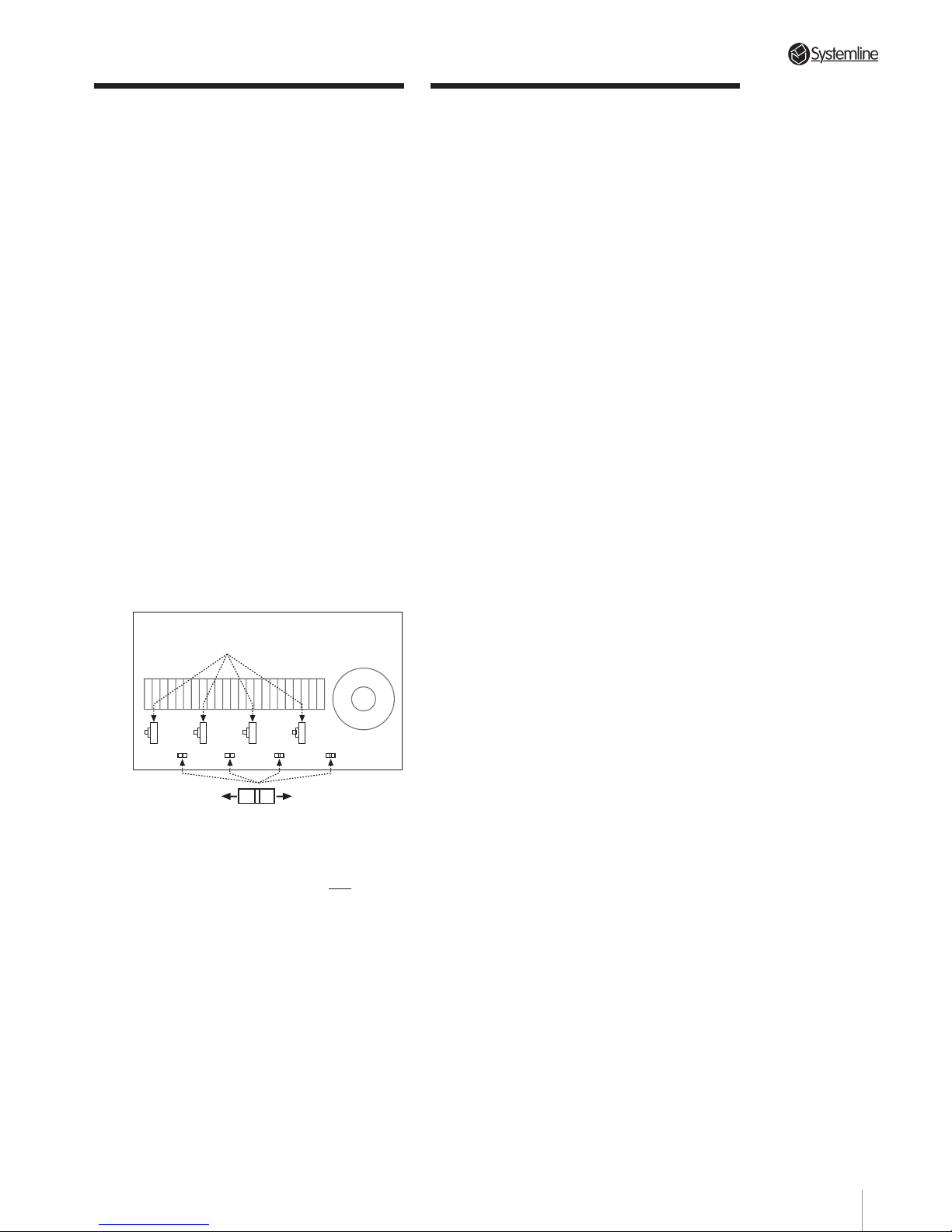
PAGE
5.5 Paging Operation
When the Paging trigger is activated, any
zone that is in standby will be turned On
automatically by the controller. The
display will show (()).
If a zone is listening to a source and the
Paging trigger is activated the controller
will automatically switch to the Paging
Input. The display will show “(())”. Any
audio present at the paging Audio IN
socket will be relayed over the speakers.
As soon as the Paging Trigger returns to
an open circuit the zone will revert to its
previous status, the clock or the original
input.
5.51 Paging Inhibit
You can select which zones will receive
an announcement when the paging is
activated. Each zone has an internal
paging switch which can be set to ON or
OFF when the top cover of the controller
is removed.
LINE DRIVER CARDS
ZONE A
ZONE B
ZONE C
ZONE D
ON
OFF
NOTE 1: If a zone is in Standby, (or is
selected to input 1,2 or 3) and its paging
switch is set to OFF, the zone
will remain
in its present status when the paging is
activated.
NOTE 2: If a zone is selected to Input 4
with its paging switch set to OFF, the
paging input will be heard when
activated.
5.6 Configuring the Pre-Out
Sockets
Each zone is equipped with a plug-in PCB Line
Driver module that enables configuration of
the output that each zone PRE-OUT socket
provides.
The factory default setting is a conventional
variable pre-amp output that can be used
directly with an external power amplifier. In
this configuration, output level is controlled
with the handset or keypad volume controls.
If a fixed level output is required, for recording
or home theatre use, each zone can be
configured independently to provide a fixed
level output from its PRE-OUT socket.
NOTE: The level of the fixed output
impedance is 220 ohms.
T o configure a zone for a fixed level output:
WARNING
Disconnect the mains supply to the
Controller before removing the top cover.
1. Remove the top cover of the controller and
locate four small plug-in PCB modules
between the front panel and the internal
heatsink. These are configured as zone A on
the left to zone D on the right when viewed
from the front of the unit.
2. Unplug the relevant PCB module, rotate it and
plug the pin header labelled ‘Line Driver’ into
the 15-way micro-socket. Ensure that pin 1 is
pointing to the rear of the controller.
3. Refit the top cover.
The source for the PRE-OUT socket is selected
using the handset or keypad, and is turned
OFF when the zone is set to Standby.
Section 5 • System Set-up
28
Page 32
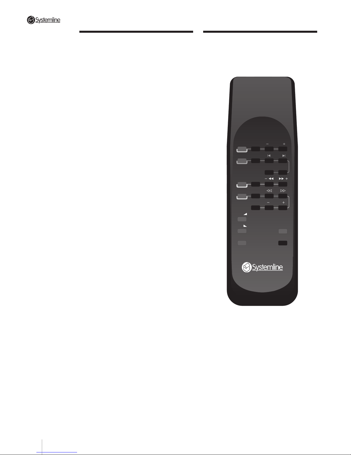
PAGE
6.1 Preliminary
Observations
Once properly installed and set up, the
S4.3 Controller Multi-Room System is
exceptionally easy to operate.
As detailed in Section 5.11, the S4.3
Controller should ALWAYS be plugged
into an uninterruptable a.c. source. This
ensures that essential S4.3 Controller
system benefits such as remote
controlled zone activation and source
selection are always available.
Zone control devices (the KMS keypad
and DMS module) are powered from the
data cables and are always active as long
as the S4.3 Controller is connected to a.c.
and switched on.
6.2 RHS Hand-held Remote
Control
TUNER
CD
FAV STN PRESETS
STOP SKIP
RANDOM DISC
TAPE/SAT STOP
VIDEO/LD
STOP
PAUSE CHNL
X
VOL
VOL
MUTE
STBY
The RHS controller provides easy and
convenient system operation from any
zone equipped with a DMS module. The
RHS/DMS’s operating range is longer and
the angle of acceptance is wider than with
many other hand held controllers. This
increased operating convenience is a
direct result of a more powerful
transmitter in the remote and more
sensitive receiving circuitry in the DMS
modules.
Section 6 • Operation
29
Page 33

PAGE
Section 6 • Operation
6.21 Input Selector Buttons
Depending on system status, pressing any
of the input buttons TUNER, CD, TAPE/SAT
or VID/DVD will do one of the following:
a) If the entire system is “Off” (i.e., the S4.3
Controller is in “Standby” mode and the
source components are powered from the
switched a.c. mains outlet), pressing any
input button will activate the zone, power
up the source components and start the
source playing.
b) If only the requesting zone is in “Standby”
(and the rest of the system, including
sources, is active), selecting an input will
enable that zone’s microprocessorcontrolled switching circuitry and direct
that source’s output to the requesting zone.
If the requested source is not already in use
by another zone, selecting the source will
also engage Play mode.
c) If the requesting zone is already playing a
different source, pushing another input
selector button will simply choose the new
source.
d) Input selector buttons for CD, TAPE/SAT
and VID/DVD double as “Play” command
buttons for their respective sources. This is
important when a source is in “Stop”
mode: Simply press the proper input
selector again to resume play.
6.22 Tuner (Source 1) Control
Buttons
Ensure that the tuner aerial is connected
and stations programmed into memory
before checking this handset feature.
a) TUNER: This selects source 1.
b) FAV. STN (Favourite Station): This will
select the first station (Preset No.1)
programmed into the tuner’s memory.
c) - PRESETS: This selects the next PRE-
PROGRAMMED station LOWER in
frequency than the one playing.
d) PRESETS +: This selects the next PRE-
PROGRAMMED station HIGHER in
frequency than the one playing.
NOTE: BOTH - PRESETS and
PRESETS + select only pre-programmed
stations; they do not perform a station
search.
6.23 CD (Source 2) Control Buttons
a) CD: This selects source 2.
b) STOP: This button stops the CD.
c) RANDOM: This instructs the single CD
player to play tracks in a random order.
On Multi Disc CD Players random tracks
are selected from the disc library.
d) DISC (functional only with multi-play CD
players): This advances the CD player to
the next available disc.
e) SKIP
: This advances the CD player to
the next track on the disc being played.
f) SKIP : This button reverts to the
beginning of the track being played. Two
quick pushes access the previous track.
6.24 Tape/Satellite or Cable (Source
3) Control Buttons
a) TAPE/SAT: This selects source 3.
b) -
(Rewind):This rewinds the tape.
Press the 'Tape' button to put the deck
back into PLAY mode.
FOR SATELLITE RECEIVER, this function
decrements the channel number.
c)
+ (Fast forward): Same as b) above
but in the opposite direction.
FOR SATELLITE RECEIVER, this function
increments the channel number.
30
Page 34

PAGE
6.25 VCR/DVD/Tuner 2/CD 2
(Source 4) Control Buttons
VID/DVD : This selects source 4 and
starts the source playing.
VCR Functions
a) STOP: This button stops the Video.
b)
(Fast reverse/Scan): This rewinds the
video tape.
c) (Fast forward/Scan): As above
except opposite direction.
d) -CHNL (Channel minus): Decrements to
lower channel number utilising the
video's built- in TV Tuner.
e) CHNL
(Channel plus): Increments to a
higher channel number.
f) PAUSE: This button pauses the VCR.
DVD Functions
a) STOP (Stop disc): This stops the DVD.
b)
(Scan back): This scans back through
the disc program.
c) (Scan forward): This scans forward
through the disc program.
d) PAUSE: This button pauses the DVD disc.
e) -CHNL This button reverts to the
beginning of the track/chapter being
viewed. Two quick pushes accesses the
previous track/chapter.
f) CHNL
: This advances the DVD player to
the next track/chapter.
Tuner 2 Functions
a) STOP (Favourite station): This button
selects the first station (Preset No 1)
programmed into the tuner’s memory.
b) —
(- Preset): This selects the next
PRE-PROGRAMMED station LOWER in
frequency than the one playing.
c)
(Preset +): This selects the next
PRE-PROGRAMMED station HIGHER in
frequency than the one playing.
d) PAUSE: No Function
e) -CHNL: No Function
f) CHNL
: No Function
CD2 Functions
a) STOP (Stop disc): This stops the CD.
b) —
(Track -): Returns the CD to the
beginning of the track being played. Two
quick pushes access the previous track.
c)
(Track +): This advances the CD to
the next track.
d) PAUSE: No Function
e) -CHNL (Random play): This instructs a
single CD player to play tracks in a
random order. On multi-disc CD players,
random tracks are selected from the disc
library.
f) CHNL (Next disc): This advances the CD
to the next disc.
6.26 VOLUME UP , VOLUME
DOWN
Press the desired button to change the
volume level in the zone.
6.27 MUTE
This temporarily reduces the zone volume
to a very low level for telephone
conversations, etc. Press Mute again to
restore volume to original level. You can
also press Volume Up, Volume Down or
any Input button to restore original level.
Section 6 • Operation
31
Page 35
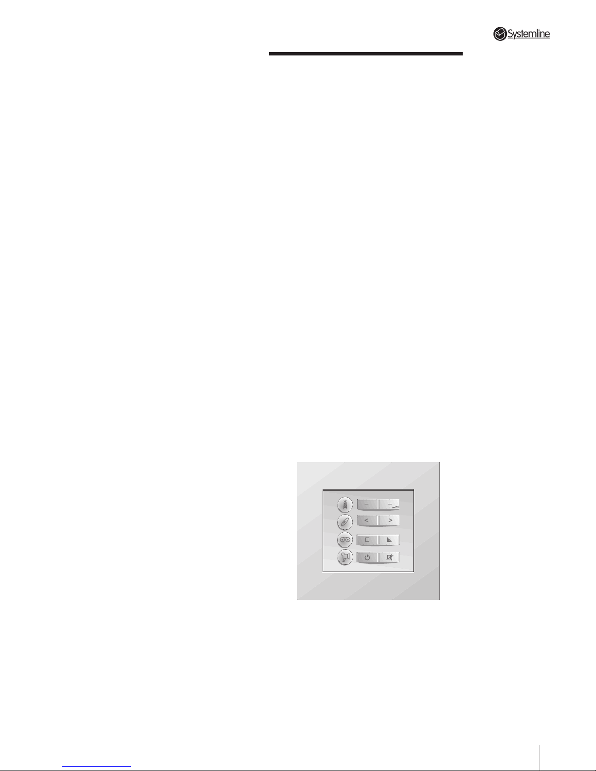
PAGE
6.28 STBY
This button has two functions:
a) A brief push will put the zone from which
the command originated into Standby
status. All other zones will remain
unaffected. Source components will
remain on.
b) A continuous push of more than 3.5
seconds will have one of the following
effects depending on the system
configuration:
NOTE: The Display will momentarily
show “Off!” to acknowledge this
command.
• In a system using only one S4.3
Controller, a continuous push of more
than 3.5 seconds will power down the
entire system including source
components.
• In a system using multiple controllers, a
push of more than 3.5 seconds will power
down all controller zones and turn all
source components connected to the
switched a.c. mains outlets OFF.
NOTE: The Control Link must be in place
for the above to work as described. It
should also be noted that the external
a.c. mains control via the TX Format
connector must be open circuit. See
section 5.14 for details.
6.29 “X”
This is reserved for future use and is
inoperative at the present time.
6.3 KMS Keypad
The KMS keypad offers easy access to
most S4.3 Controller system functions. It
has eight individual keys to send
commands to the S4.3 Controller.
6.31 Key Functions
The keys in the left column each select a
connected source with a single press the
top key selecting source 1 and the bottom
key selecting source 4. Pressing any
source key automatically activates the
zone if it is in standby and selects the
source; if the zone is already active, it
changes to the new selected source.
NOTE: When delivered, the key caps for
sources 3 and 4 keys are not fitted. A
selection of key caps, appropriate to all
possible source components connected
as sources 3 and 4, are provided for
fitment during installation. This enables
the KMS to correctly indicate each
connected source.
The keys in the right column provide
command functions. The upper and lower
keys provide standard system functions
applicable to any selected source. The
functions provided by the two centre keys
change automatically depending on the
selected source.
Section 6 • Operation
32
Page 36
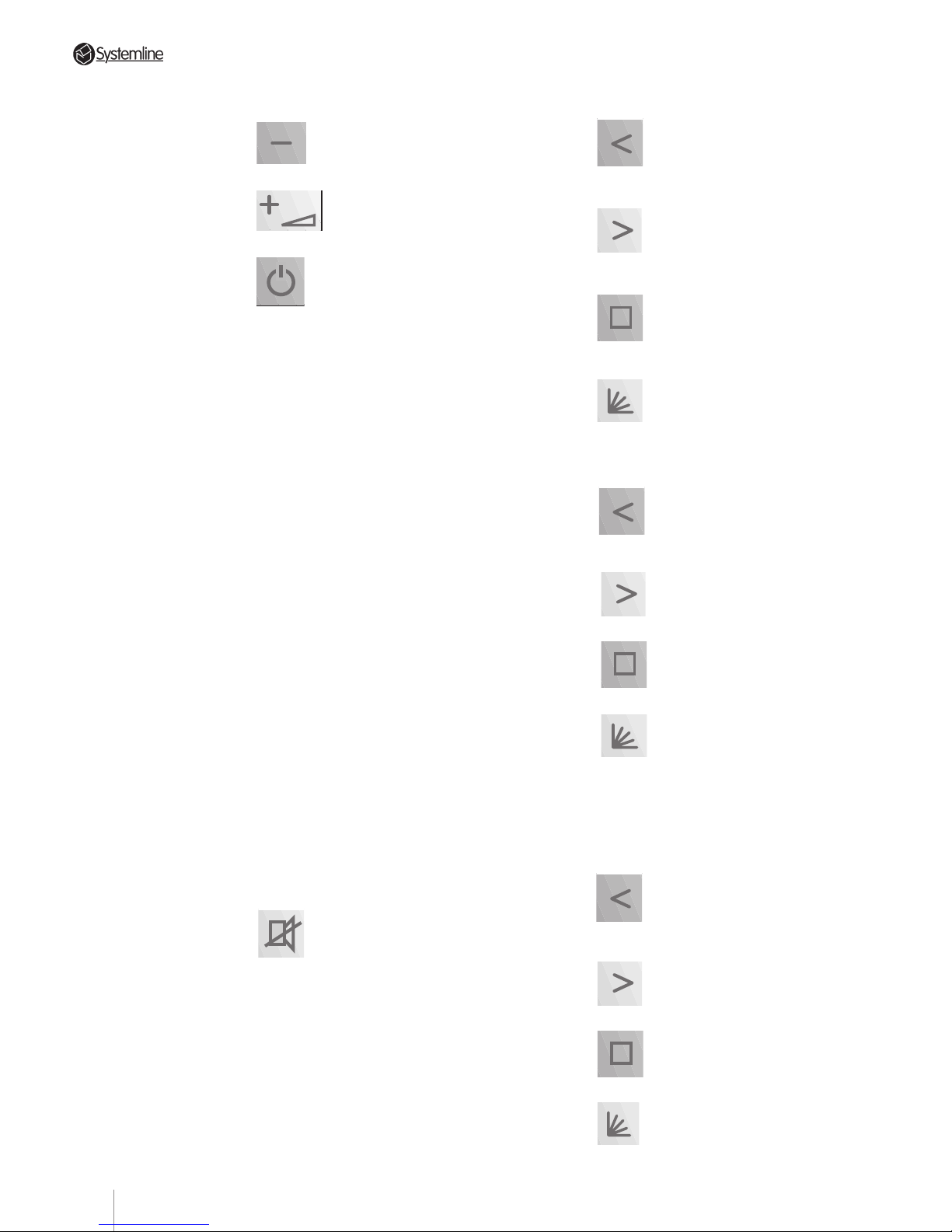
PAGE
Section 6 • Operation
6.33 Tuner (Source 1) Commands
(-Preset): This selects the
next PRE-PROGRAMMED
station LOWER in frequency
than the one playing.
(Preset +): This selects the
next PRE-PROGRAMMED
station HIGHER in frequency
than the one playing.
(Favourite station): This
selects the first station
(Preset No 1) programmed
into the tuner’ s memory.
No Function
6.34 CD (Source 2) Commands
(Track skip back): This
reverts to the beginning of
the track being played. T wo
quick pushes select the previous track.
(Track skip forward): This
advances the CD to the
next track.
(Stop disc): This stops the
CD.
(Next disc): This advances
the CD to the next disc
(when appropriate).
6.35 T ape Deck/Satellite/Cable
(Source 3) Commands
Tape Deck
(Fast rewind): This rewinds
the tape. Press source 3 key
to put the deck back into
Play mode.
(Fast forward): Same as
above except in the forward
direction.
(Stop tape): This stops the
tape deck.
No Function
6.32 System Commands
(Volume -): Press to decrease
volume in the zone.
(Volume +): Press to increase
volume in the zone.
(Standby): This button has two
functions:
a) A brief push will put the zone from which
the command originated into Standby
status. All other zones will remain
unaffected. Source components will
remain on.
b) A continuous push of more than 3.5
seconds will have one of the following
effects depending on the system
configuration:
NOTE: The Display will momentarily
show “Off!” to acknowledge this
command.
• In a system using only one S4.3
Controller, a continuous push of more
than 3.5 seconds will power down the
entire system including source
components.
• In a system using multiple controllers, a
push of more than 3.5 seconds will power
down all controller zones and turn all
source components connected to the
switched a.c. mains outlets OFF.
NOTE: The Control Link must be in place
for the above to work as described. It
should also be noted that the external
a.c. mains control via the TX Format
connector must be open circuit. See
section 5.14 for details.
(Mute): This temporarily
reduces the zone volume to a
very low level for telephone
conversations, etc. Press Mute again to
restore the volume to the original level.
Pressing the volume control key (up or down)
or any source key will also restore volume.
33
Page 37
PAGE
Section 6 • Operation
Tuner 2
(- Preset): This selects the next
PRE-PROGRAMMED station
LOWER in frequency than the
one playing.
(Preset +): This selects the next
PRE-PROGRAMMED station
HIGHER in frequency than the
one playing.
(Favourite station): This selects
the first station (Preset No 1)
programmed into the tuner’s
memory.
No Function
CD 2
(T rack skip back): This reverts to
the beginning of the track being
played. T wo quick pushes select
the previous track.
(Track skip forward): This
advances the CD to the next
track.
(Stop disc): This stops the CD.
(Next disc): This advances the
CD to the next disc (when
appropriate).
Satellite or Cable
(- Channel): This changes to a
lower channel number.
(Channel +): This changes to a
higher channel number.
No Function
No Function
6.36 VCR/DVD/Tuner 2/CD 2
(Source 4) Commands
VCR
(Fast rewind / scan back): This
rewinds the tape, with scan if
the tape is being played when
the function is selected.
(Fast forward / scan forward):
Same as above except in the
forward direction.
(Stop VCR): This stops the VCR.
(VCR Ch+): This advances the
VCR to the next channel.
DVD
(Scan back): This scans back
through the disc program.
(Scan forward): This scans
forward through the disc
program.
(Stop disc): This stops the DVD.
No Function
34
Page 38
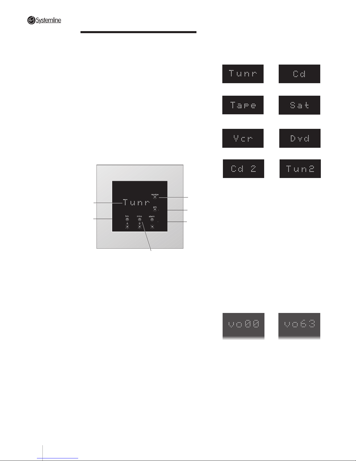
PAGE
6.43 Dot Matrix Display
a) Selected Source: The display shows the
in-use source as follows:
Source 1 Source 2
Source 3 - T ape Deck Source 3 - Satellite
or Cable
Source 4 - VCR Source 4 - DVD
Source 4 - CD 2 Source 4 - Tuner 2
b) Clock Display and Greeting: When a zone
is in standby mode, the time is displayed
in 4-digit 12hr format. When the zone is
activated, the DMS shows a scrolling
greeting 'Good morning', 'Good
afternoon' or 'Good evening' appropriate
to the time of day. At shutdown and
between 10pm and midnight the DMS
shows 'Good night'. When a zone is
active, pressing the alarm button will
display the time.
c) Volume Level: When a Volume control
command is sent, the DMS will display a
2-digit number counting up or down
between vo 00 (min. volume) to vo 63
(max. volume).
When a Mute ON signal is sent the
volume level decreases to zero and the
DMS displays the message 'Mute'. On
receipt of a Mute off, or source select, or
volume up/down command signal, the
display will return to its previous level.
Minimum Volume Maximum Volume
1
2
3
6
4
Section 6 • Operation
6.4 DMS Module
6.41 Overview
When a zone is active, the DMS module
responds to control commands from the RHS
handset, the KMS keypad and also from other
infra-red devices. It displays appropriate
system status messages.
When a zone is at Standby, the DMS displays
the time.
If the DMS display is blank, this indicates that
the S4.3 Controller is switched Off.
6.42 Controls and Indications
1 receive LED: This lights when the DMS receives
a signal (infra-red code) from the handset or
from the KMS keypad in the same zone.
2 pm LED: This lights up between 12 noon and
12 midnight.
3 alarm button and LED: The button is used when
setting the alarm and clock time. The LED is lit
when the alarm is set.
4 hrs / A button and LED: This button is used (as
hrs Button) when setting the time or alarm and
also, when appropriate, (as A speakers button)
to control speakers connected to the A output
on the Zone Splitter .
5 mins / B button and LED: This button is used
(as minutes button) when setting the time or
alarm and also, when appropriate, (as B
speakers button) to control speakers connected
to the B output on the Zone Splitter .
6 Dot Matrix Display: This is used to display the
time and appropriate status and setup
messages, as described below.
5
35
Page 39
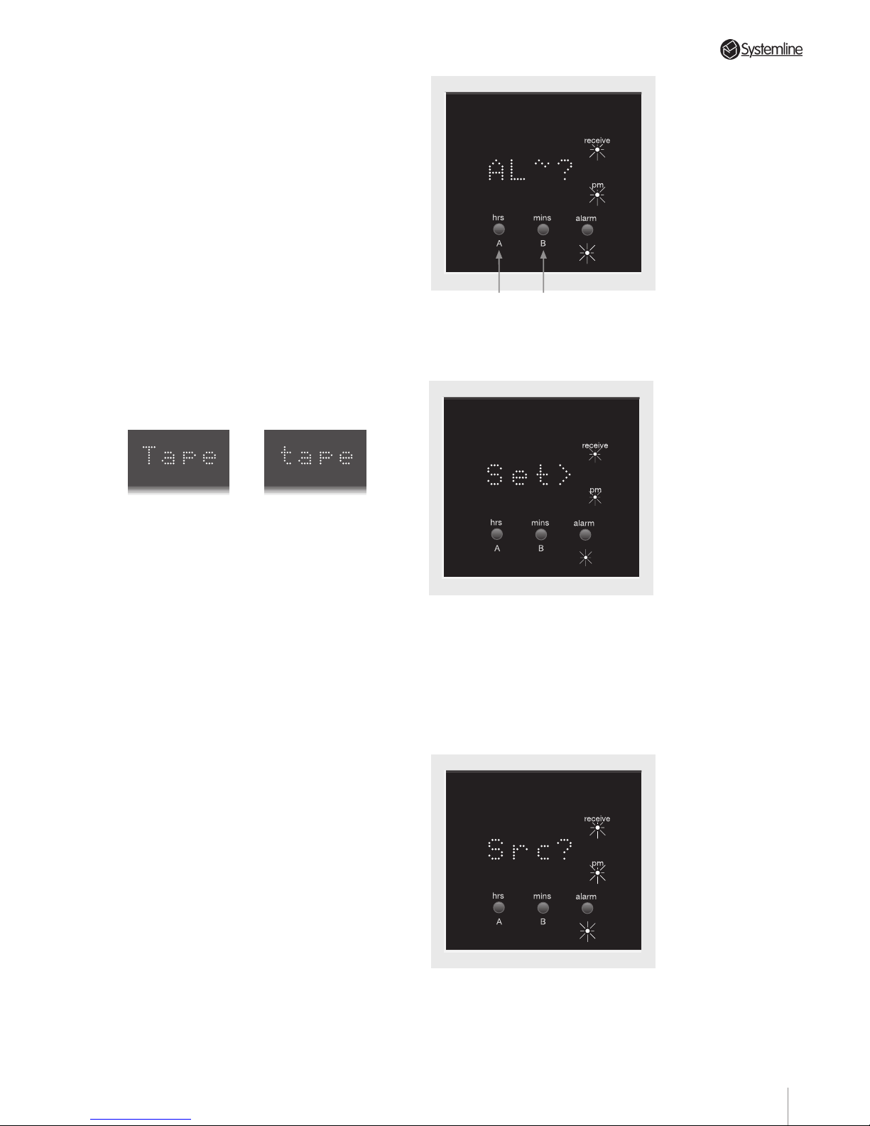
PAGE
35
Section 6 • Operation
If a zone is active and a Paging signal is
received, the volume level decreases to
zero and the DMS displays '(())'. If a
Paging signal is received while the zone
is muted, the DMS display will
immediately show '(())'.
If the zone is in standby mode and a Paging signal is received, the DMS will display the appropriate greeting for the time
of day and then '(())'.
d) Automatic Brightness Adjustment: An
ambient light sensor in the DMS module
adjusts the brightness of the display as
the background lighting varies, to give a
more even perceived brightness.
e) Engaged Indication: If a source is
engaged, the leading character of the
selected source is shown in lower case.
f) Internal Battery Indication: If the time
display flashes when a DMS module is
first connected, this indicates either that
the clock has not been set or that the
battery has not been enabled - see
Section 4.21 DMS Module. If the display
flashes after the system has been turned
off for a period of time, this indicates that
the internal battery charge is low. The
clock time should be reset to stop the
flashing and the system left On for a few
days to recharge the internal battery.
6.44 Operation
With the zone in Standby, the DMS
module displays the time. Use the
handset or keypad as previously
described in Sections 6.2 and 6.3 to select
the required functions.
6.45 Setting Alarms and Time
With the DMS zone in Standby mode,
press the alarm button. The display will
show the first 'Mode' function.
Repeatedly pressing the alarm button will
step through the remaining functions and
return the DMS to Standby mode (a total
of five steps).
ZONE ENGAGEDSOURCE SELECTED
1. Select Alarm
Press the hrs/A button to select alarm off,
or the mins/B button to select alarm on.
3. Select Source
Select the source to play when the alarm
is activated. Press the hrs/A button to
select tuner, or the mins/B button to
select CD.
2. Set Alarm Time
The display will show the last alarm time
set. Use the hrs/A and the mins/B
buttons to advance to the required alarm
time.
NOTE: Make sure that the pm indicator is
also showing the correct 12hr period for
the alarm.
ONOFF
36
Page 40
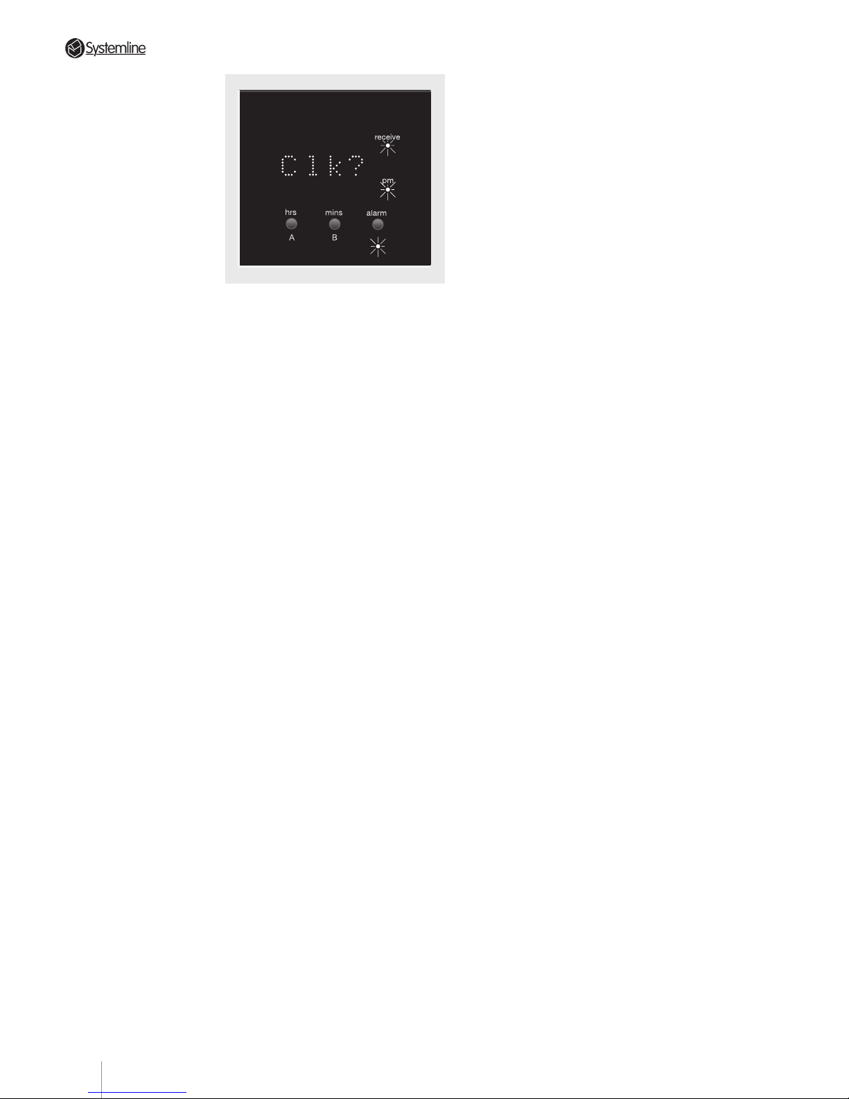
PAGE
NOTE: The clocks in different zones may
be slightly out of synchronisation due to
drift or inaccurate setting. They will be
synchronised automatically at 12 noon
each day with the master system clock in
zone A.
5. Return to Standby mode
Pressing the alarm button exits the Mode
function.
NOTE: If a DMS is set as a slave (See
Section 4.21 DMS Module) only the clock
can be set. Only one alarm in each zone
is permitted.
6.46 Zone Splitter Control
If a zone is divided into two separate
areas through the installation of a second
set of speakers and a Zone Splitter, the
prime DMS within that zone is used to
control the Zone Splitter and direct a
selected source input to either or both
areas.
To set the DMS in ‘Zone Splitter’ mode,
press both the A and B buttons on the
prime DMS and hold them pressed for six
seconds. The A and B LEDs illuminate as
appropriate to indicate the status of the
speakers in the A and B areas. If an LED is
lit, that speaker pair is switched ON.
If both speaker pairs are On (both LEDs
illuminated), one pair can be switched Off
by pressing the appropriate A or B
button.
4. Set Clock
Use the hrs/A and mins/B buttons to
advance to the required clock time.
If one speaker pair is switched On, the
other set can also be switched On by
pressing the appropriate A or B button.
Alternatively, to switch from one set to
the other, both A & B speakers must be
switched ON before turning the other set
OFF.
NOTE 1: It is not possible to switch BOTH
pairs of speakers Off - this avoids the
possibility of having no audio output
when a zone is active.
NOTE 2: The A and B button Zone
Splitter control function is active
whether the zone is Active or in Standby.
NOTE 3: When a Zone Splitter is used,
both pairs of speakers will share the
same volume level and source.
Section 6 • Operation
37
Page 41
PAGE
7 Specification
Number of audio channels: 8 (4 x Stereo)
Number of audio inputs: 4 Stereo.
Audio loop out frequency response: 20Hz-20kHz +/- 0.8dB into 22k Ohms.
Audio loop out distortion: THD+N <0.005% 20hz-30kHz bandwidth.
Audio loop out level: -0.14dB lower than Input level.
Pre-Amplifier Output
Fixed & variable level output: frequency response 20Hz-20kHz +/- 0.8dB
Fixed level output distortion: THD+N 0.005% @1kHz
Variable level output distortion: THD+N 0.01% @1kHz
Power Amplifier Output
Frequency response: 20Hz-20kHz +/- 1dB
Distortion: THD+N 0.07% into 5 Ohms @ 13W
Output power per channel: 23W into 5 Ohms @ <0.4% THD+N
Dimensions: 430mm (w) x 360mm (d) x 98mm (h)
Weight: 9.8kg
Max Power Consumption: 430Watts
QED Audio Products Ltd. reserves the right to alter the specifications of the
products described in this manual at any time and without prior notice.
Section 7 • Specification
38
Page 42
PAGE
QED FAX BACK
FAX TO: (01483) 545600
SOURCE COMPONENT COMPATIBILITY PROBLEM
Controller Serial Number:
Installer/Dealer Name:
Your Fax Number:
Your Telephone Number:
1st Component Type. CD etc.
Brand. SONY, Denon etc.
Model Number:
Details of problem....
2nd Component Type:
Brand:
Model Number:
Details of problem....
3rd Component Type:
Brand:
Model Number:
Details of problem....
Any other comments
39
Page 43

PAGE
40
Page 44
UNIT 16-WOKING BUSINESS PARK ■ ALBERT DRIVE ■ WOKING■ SURREY ■ GU21 5JY ■ ENGLAND
SYSTEMLINE IS A DIVISION OF QED AUDIO PRODUCTS LTD
We operate a policy of continual improvement and reserve the right to improve designs and specifications without prior notice.
 Loading...