

Page 1

Wireless Touchscreen
Installation Guide
Page 2

Page 3

PAGE
3
Declaration of
Conformity
The Systemline Wireless Commander has been
designed and independently tested to be in
compliance with the following standards:
EMC in line with the R&TTE directive 1999/5/EC
EN 301 489-1 V1.8.1
EN 301 489-17 V1.2.1
Radio services in line with the R&TTE directive
1999/5/EC
EN
300 328 v1.7.1
Safety serices in line with the R&TTE directive
1999/5/EC
EN 60950 with combined US and Canadian
version of the UL mark cULus under UL 60065
and IEC 60065
Safety
This Symbol is to alert the
user to the presence of
dangerous voltages inside the
Systemline Modular Power
supplies. To reduce the risk of
electric shock do not
dismantle these power
supplies.
This symbol is to alert the
user of important operating
instructions included on the
CD-Rom accompanying the
Systemline Modular system.
Read all the instructions
before connecting or operating the Systemline
Modular system. Pay particular attention to the
safety information. Keep this manual so you
can refer to the safety instructions.
WARNING: There are no user serviceable parts
inside. Refer all servicing issues to qualified
personnel.
WARNING: To reduce the risk of fire or electric
shock, do not expose the Systemline Modular
system to moisture or water. Do not allow
foreign object to get into any part of Systemline
Modular system. If moisture or foreign bodies
get inside any part, immediately disconnect the
power cord from the wall. Obtain assistance
from a qualified service person. No objects
filled with liquids, such as vases, shall be placed
on any part of Systemline Modular system.
That no naked flame sources such as candles
should be placed on any part of Systemline
Modular system.
Ventilation should not be impeded.
Ensure that the Systemline Modular
components are fitted in accordance with their
individual installation instructions.
Copyright and
acknowledgements
Copyright © 2009 Armour Home Electronics Ltd.
All rights reserved.
The information in this guide is believed to be
correct as of the date of publication. However,
our policy is one of continuous development
and so the information is subject to change
without notice, and does not represent a
commitment on the part of Armour Home
Electronics Ltd.
Systemline is a registered trademark of Armour
Home Electronics Ltd. All other product names
are trademarks or registered trademarks of their
respective owners.
Stortford Hall Industrial Park
Dunmow Road
Bishops Stortford
Hertfordshire CM23 5GZ
Web: www.armourhome.co.uk
About this guide
This Wireless Touchscreen Installation Guide
is aimed at audio installation engineers, or
trained qualified electricians, involved in the
actual installation and interconnection of a
Systemline system. It is meant to complement
the installation manuals for Systemline
Modular Advanced or Systemline S6 Multiroom systems.
Page 4

Table of Contents
PAGE
4
1 Introduction 5
Commander 5
Charging Station 5
Wireless Junction Box 5
2 Wiring the System for the
Commander 6
2.1 Introduction 6
2.2 Wiring up a Modular zone using SLM3 speakers 6
2.3 Wiring up a Modular zone using OW2 on-wall
speakers 7
2.4 Wiring up a Modular zone using a ZAM unit 7
2.5 Wiring up an S6 zone 7
3 Products in Detail 9
3.1 Wireless Commander 9
3.2 Wireless Junction Box 10
3.3 Charging Station 10
4 Software Configuration 11
4.1 Update Hub Firmware 11
4.2 Address All Touch Screens and Wireless Boxes 11
4.3 Update Wireless Commander Firmware 12
4.4 Configuration Tab 12
4.5 Profile 12
4.6 Upload Zone Configuration 12
Page 5

PAGE
5
Section 1 • Introduction
1 Introduction
The Systemline Wireless Commander can be used with both Modular
Advanced and S6 Multi-room systems, giving all the benefits of the
wired touch screen in your hand. This manual shows you how to plan,
connect and configure wireless Commander touchscreens to your
project and should be used in conjunction with the SystemNet 6-port
hub instructions included in the Hub or S6 unit.
The Commander system consists of three
parts:
Commander
This is the wireless touch screen handset
itself and contains a 2.4GHz two way radio
interface. The Commander offers all the
features supported by the wired touch
screen but also has the ability to control
any wirelessly enabled zone in the system.
The Commander is sold with a matching
charging station.
Charging Station
This unit charges the Commander Touch
screen and includes a 9V DC power
supply. There is a small blue LED on the
front which will illuminate for a period
of time when the Commander is docked
correctly. This unit is available separately,
so there can be more than one location for
a Commander to recharge.
Wireless Junction Box
This is a small unit that contains a
2.4GHz two-way radio interface and all
the connectivity to control a Systemline
Modular or S6 zone. Every zone that
requires wireless Commander control
must contain a wireless junction box.
This unit is sold separately so you can
activate up to 8 zones with one or more
Commanders.
Page 6

PAGE
6
Section 2 • Wiring the System
2 Wiring the System for the
Commander
This chapter gives information about preparing and wiring your
Systemine S6 or Modular Advance Multi-room system for use with the
Wireless Commander.
2.1 Introduction
The Commander is only compatible with
Systemline S6 or Systemline Modular
Advanced Multi-room systems (with a
6 port SystemNet Hub). Each zone must
have a Wireless Junction Box for it to
connect to the wireless system and allow
Commander Control.
SystemNet supports up to eight
Junction Boxes and up to eight Wireless
Commanders. This does not affect the
number of wired touch screens, which
remains up to one per zone with a
maximum of eight in total. You can also
mix KMP7 or LKPM7 keypads with the
Wireless Commander in any zone. It is
possible to use a Wireless junction box
with no keypad connected, operation by
Commander only.
The following wiring schematics below
only show the SystemNet part of wiring,
and not the audio or video wiring which
remains unchanged.
We have shown an example of the
Commander used in each possible
Systemline scenario.
2.2 Wiring up a Modular
zone using SLM3
speakers
The wireless junction box can be used in
any zone where control from a Wireless
Commander is required. All zones with a
wireless junction box can be controlled
from one Wireless Commander.
A wired touch screen, LKPM7 or KMP7 is
optional and not necessary for wireless
commander control, but simply wires into
the junction box via a single Cat5e cable in
the normal way.
Wireless Junction Box
SLM3 Active Speaker
SystemNet
Hub
Wired Touchscreen
Keypad (TSK) or
KPM7/LKPM7 Keypad
Modules
CAT5E Cable
The Cat5 wiring requirement for wireless
control is the same as a normal wired
touch screen zone, so you will just need
to replace the current M-SNB with the
Wireless junction box behind the active
speaker in the ceiling.
NOTE:
Please beware of metal foil lined
ceiling plaster as this could seriously
degrade the wireless signal.
Y
ou will use the following RJ45 sockets on
the junction box:
Speaker Keypad
Wired
Keypad (optional)
S
ystemNet Hub
Page 7

PAGE
7
Section 2 • Wiring the System
2.3 Wiring up a Modular
zone using OW2 onwall speakers
Wireless Junction Box
OW2
On-wall Speaker
SystemNet
Hub
Wired Touchscreen
Keypad (TSK) or
KPM7/LKPM7 Keypad
Modules
CAT5E Cable
Local Input (SIM)
SIM
IN
OUT
AUDIO
LRL
R
RJ45 Socket
The Modular on-wall speaker M-OW2 does
not have enough space to fit the wireless
junction box behind it, so a suitable place
must be provided with the correct Cat5
cables as shown above.
Any wired touch screen or keypad needs a
single Cat5 cable to the junction box and
not
the speaker.
The SystemNet Hub Cat5 cable must wire
to the junction box and not the speaker.
The junction box has a single Cat5 cable to
the active on-wall speaker. If a local input
is also needed, then this must share the
single RJ45 connector on the back of the
speaker. The junction box speaker keypad
cable requires only the brown and blue
pairs, and the local input SIM/WE module
requires only the green and orange pairs.
You will use the following RJ45 sockets on
the junction box:
Speaker Keypad
Wired
Keypad (optional)
S
ystemNet Hub
2.4 Wiring up a Modular
zone using a ZAM unit
Wireless Junction Box
ZAM
Zone Amp Module
SystemNet
Hub
Wired Touchscreen
Keypad (TSK) or
KPM7/LKPM7 Keypad
Modules
CAT5E Cable
The wireless junction box can be placed
next to the ZAM unit, as long as the
position of the ZAM is central or near
by the desired operation of the wireless
commander.
You will use the following RJ45 sockets on
the junction box:
Speaker Keypad
Wired Keypad (optional)
S
ystemNet Hub
2.5 Wiring up an S6 zone
Wireless Junction Box
S6 Controller
Wired Touchscreen
Keypad (TSK) or
KPM7/LKPM7 Keypad
Modules
CAT5E Cable
The wireless junction box must be placed
between the wired touchscreen or keypad
and the S6 Controller as shown. Ideally
the junction box is still in close proximity
Page 8

PAGE
8
Section 2 • Wiring the System
to the zone, so new installations should
route the Cat5 cable from the wall keypad
to a suitable location first and then to the
S6 unit.
You will use the following RJ45 sockets on
the junction box:
Wired Keypad (optional)
S6
Page 9

PAGE
9
Section 3 • Products in Detail
3.1 Wireless Commander
The Commander has the same 3.5” VGA
colour touch screen as the wired touch
screen. It has six hard buttons, three on
each side with the following functions.
Power:
Turns the currently selected zone
on or off.
Room:
Will display all available zones in
the system for Commander Control, and
allow a new selection.
Home:
Displays all available sources, and
also acts as a menu back function
Volume Up: Adjusts the volume up
Mute:Mutes
the audio
Volume Down:Adjusts the volume down
There is no IR receiver or room brightness
sensor, unlike the wired touch screen. IR
signals are sent from the Commander to
the Junction Box which then transmits
IR back to the Hub or Local input plate.
The Commander will switch its backlight
off after a set time, and the brightness
is adjustable so no room brightness
adjustment is needed.
The Commander is supplied with a
rechargeable NiMH battery pack which
is disconnected at the factory. You must
unscrew the battery cover and connect
the battery before proceeding with the
configuration.
1. Unscrew the battery cover
2. Plug in the battery
3. Screw the battery cover back on
You should then place the Commander
onto the Charging Base Station.
The Commander has a USB port behind a
rubber flap which is used for configuration
uploads from the SystemNet Application
software. See section 4.0 for configuration
details.
In order to conserve battery life, the
Commander will firstly switch the
backlight off after a set (adjustable) period
of time, and then close down the main
operation after five minutes.
The Commander has a built in mercury
balance switch which is used to activate
the screen quickly when it is picked up.
Alternatively, pressing the screen or
any hard buttons will also reactivate the
screen within 2 seconds. Once active
again, you can use it normally.
3 Products in Detail
A starter pack will contain all you need to make one zone work with
the Wireless Commander. Additional Junction Boxes, Charging Base
Stations and Commander Units can be purchased separately to expand
the system.
Page 10
PAGE
10
Section 3 • Products in Detail
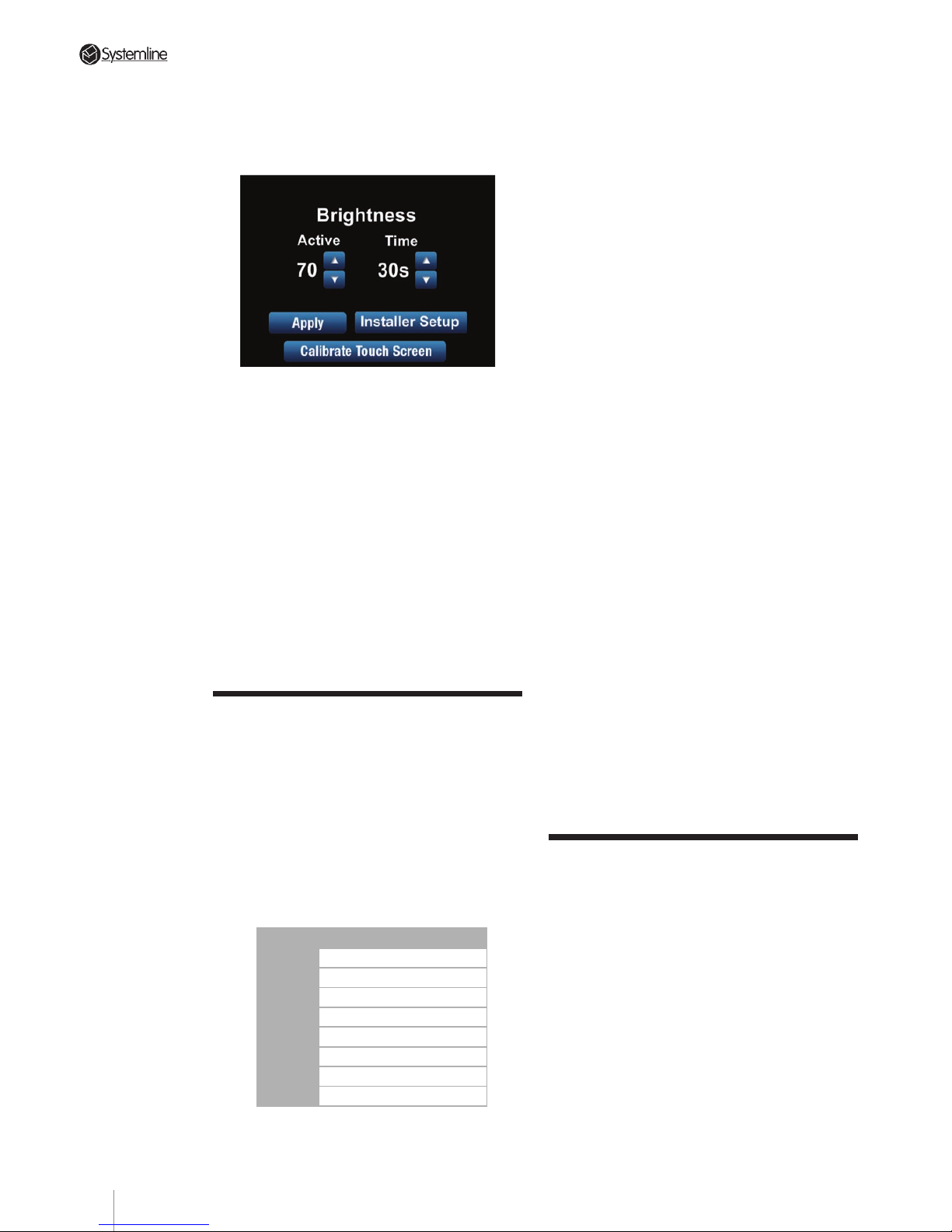
The brightness and active time can be
adjusted by pressing and holding down
the volume up, volume down and mute
buttons together.
The brightness active adjustment is a
value from 0 to 99 and will adjust in real
time so the desired setting can be made
easily. This screen brightness will be
applied for a set period of time adjustable
from 0 to 60 seconds. Once you have
made the adjustment, press ‘Apply’ to
make the settings permanent.
The touch screen’s accuracy can also be
adjusted by pressing the ‘Calibrate Touch
screen’ button. You should use this if the
screen is not responsive in the correct
area.
3.2 Wireless Junction Box
The Wireless Junction Box is used for each
zone where Wireless Commander control
is required. It is contained within a plastic
enclosure which can be DIN rail mounted,
fixed to a wall, or left freestanding.
The four RJ45 connections should be
used with RJ45 plugs wired to TIA-568B
standard network wiring.
PIN Colour
1 White/Orange
2 Orange/White
3 White/Green
4 Blue/White
5 White/Blue
6 Green/White
7 White/Brown
8 Brown/White
The radio antenna is located on the
opposite face to the RJ45 connections, so
the unit is best positioned with the radio
face pointing towards the zone.
The system uses 8 different frequencies
to communicate with the Commander
and will monitor background noise
automatically and switch frequency if
needed. This is an automatic process
and does not need any adjustment or
configuration by the installer or end user.
A Commander can operate any activated
zone in the system through the currently
connected Junction Box. This allows
the user to switch zones, operate lights,
volume etc. without having to move from
their current position.
The Wireless Junction Box has two status
LED’s showing wireless and wired (hub)
data activity. Normally the hub light will
flash every second or so, the wireless
light should only flash when using a
Commander connected to box. If they are
not flashing at all or on continuously then
you may have a bad connection or severe
background RF noise.
The wireless junction box will store all
IR data for the zone when controlled
by a Wireless Commander. IR is then
transmitted to the S6 unit or AM8 hub
via the speaker or ZAM unit. This makes
it possible for the Wireless Commander
to operate IR devices, even local devices
without directly transmitting IR from the
front. Please ensure you upload the .qrc
file to each junction box as covered in
section 4.6.
3.3 Charging Station
The charging station is supplied with each
Wireless Commander unit and comes with
a 9V 2A DC power supply which should be
connected to the rear socket. The station
contains a moulded recess which matches
the outline of the Commander, making it
easy to locate the Commander to charge
the battery. There are four steel contacts
on the charger which connect to the four
copper strips on the underside of the
Commander.
Page 11

PAGE
11
Section 3 • Products in Detail
When correctly docked the blue LED
on the front of the charging station will
illuminate for approximately 15 seconds.
The Commander can still be used when
docked in the charging station, and does
not use any power from the battery in this
case. You should find that the Commander
docked in the charging station is angled
towards the user if mounted on a table or
desk.
Take care to avoid damaging the charging
pins on the Charging Bass Station as
this may cause intermittent charging
operation.
Page 12

PAGE
12
Section 4 • Software Configuring
4.1 Update Hub Firmware
You should update the hub firmware to
12.0 (or higher) before proceeding any
further, otherwise the hub or S6 will not
recognise Wireless junction boxes.
1. Plug in the USB cable
2. Plug in one wired touch screen
3. Press ‘Query All Keypads’
4. The software will return with the keypad
address and suggest that firmware is
updated.
5. Press ‘Yes’ and the system will continue
updating hub and keypad firmware to
version 12.0 or later.
4.2 Address All Touch
Screens and Wireless
Boxes
It is possible to use 8 wired touch
screens and 8 Wireless junction boxes
in one system, so there are now 16
possible addresses to use and allocate.
The Wireless Commander handsets
themselves do not have an address, but
rather the wireless junction boxes, which
are wired into the S6 or 6 port hub unit.
The process of allocating addresses is
very similar to previous versions but we
recommend that you address wireless
boxes and wired touch screens on a zone
by zone basis.
1. Plug only one zone in to be addressed
(this may contain a wired keypad and
wireless box).
2. Choose an address for the wired keypad
and press ‘Add/Address Keypad’.
3. Add a profile if you wish.
4. Choose an address for the wireless box
and press ‘Add/Address Wireless’.
5. Add a profile if you wish.
6. Disconnect this zone, and then connect
the next zone to be addressed and repeat
the steps above.
7. Plug in all zones once addressing is
complete and press ‘Query All Keypads’.
You should get a response from all
devices with their address and firmware
and a prompt to update all firmware
versions to the one you are running,
proceed with the update.
8. Once the addressing and firmware
update is complete, pressing ‘Query
All Keypads’ should give a complete
response as shown above.
4 Software Configuration
The Commander system comes with a CD containing the SystemNet
Configuration software. You should install this software on your machine
before proceeding any further. This step by step instruction should be
used in addition to the SystemNet S6 or 6 port Hub instructions and
refers to the addition of Wireless Commanders only.
Page 13

PAGE
13
Section 4 • Software Configuring
4.3 Update Wireless
Commander Firmware
You should make sure all Commander
Units have your version of firmware, by
plugging in one at a time using a USB
cable.
1. Unplug from the Hub or S6 (Important
as the next step will not work).
2. Select ‘Wireless’ from the drop down
menu in Firmware, Selected keypad.
3. Press ‘Get Firmware Versions’
4. Follow the prompt to upgrade firmware
if required.
5. Unplug Commander, and repeat the
process for all in the project.
4.4 Unique System
Identification Code
Version 12.0 or above with wireless
touch screens use a unique code for
each system. This is to prevent cross talk
between two systems in close proximity,
for example in an apartment above that
also has a Systemline wireless zone with
the same junction box address. Each
communication between a Commnder
and a system uses the ID code and must
be correct to operate the system.
The SystemNet software will allocate an
ID code when 1st plugged into an S6 or 6
Port Hub and a ‘Query All Keypads’ or ‘Set
To PC Time’ button is pressed. Once the
unit has been allocated a code it retains it
and will be displayed if any of the above
communications occur at the bottom right
corner of the ‘Local Hub Network’ tab
page as shown.
It is vital that the correct system ID is
shown when you upload a configuration
to a Wireless Commander, otherwise the
Commander will not operate your system.
Always press ‘Set To PC Time’ or ‘Query All
Keypads’ to get the ID before you upload
to a Wireless Commander, otherwise an
error message will be displayed.
The system ID is not stored in the .snc
file you will save on your PC. This is to
prevent the same configuration file being
uploaded to multiple systems with the
same System ID. It is only stored in the S6
or 6 Port Hub.
4.5 Configuration Tab
Add configurable Sources and inputs in
the normal way
4.6 Profile
Each address can be named in the
Description box, and the device type can
be selected or changed from Colour, Black
& White or Wireless. Please make sure
that the profile is correct for each of the
addresses that you have in your project.
The description given for each wireless
Page 14

PAGE
14
Section 4 • Software Configuring
box will be displayed on the Commander
when the room buttons is pressed.
Lighting and heating control can be added
in the normal way to any selected wired or
wireless keypad.
IR data must be loaded into wireless
profiles; this is then loaded into the
junction box which then transmits the
correct IR signal for any IR devices you
wish to control.
A local input source can be added to each
profile in the normal way.
4.7 Upload Zone
Configuration
You must upload a configuration to each
wired touch screen and wireless junction
box when connected to an S6 or six port
hub unit via the supplied USB cable. You
may choose a single address upload or
multiple upload.
It is possible to configure Wireless
Commander Touch screens to operate any
number of zones from one to eight. You
can select the zones that a wireless screen
operates by firstly selecting a wireless
zone in the ‘Selected Configuration
Profile’, then selecting ‘Wireless Zone
Control’. This will bring up a window with
all available wireless zones; you can select
any number you wish before proceeding
with the Commander upload.
In this example, the Commander generally
used for the garden will also be able to
operate all other wireless zones in the
system.
Once you have selected the zones, make
sure you have disconnected the USB cable
to the S6 unit or SystemNet Hub before
connecting the USB cable to a charged
Commander. You can then select ‘Upload
wireless keypad’, and the software will
then upload.
PLEASE NOTE: If you make a change to
the configuration profile of a wireless zone
such as adding a lighting scene button,
you must upload the zone configuration
to the wireless junction box as well as the
wireless Commander; otherwise this new
button will not work. To do this quickly,
select the wireless junction box profile
and select ‘Upload Without IR’. This will
upload all the required data to the hub
for the additional buttons or changes you
have made.
Page 15

PAGE
15
Page 16

PAGE
16
Page 17

PAGE
17
Page 18

PAGE
18
Page 19

Page 20

Stortford Hall Industrial Park,
Dunmow Road, Bishops Stortford,
Hertfordshire CM23 5GZ
United Kingdom
Web: www.armourhome.co.uk
Email: info@armourhome.co.uk
Our policy is one of continuous product improvement, we reserve
the right to change the designs and specifications without notice.
All information is given in good faith. The manufacturer accepts
no responsibility for errors, omissions or incorrect assumptions.
Armour Home Electronics 2009
ZINS158/ISS2/151009
w w w . sy s t e m l i n e . c o . u k
 Loading...