

System Equine TRC-6, TRC-8, TRC-PULL-BEHIND-8, TRC-PULL-BEHIND-6 Assembly Instructions Manual
System Equine
14321 Fifth Line Nassagaweya • Rockwood, ON • N0B 2K0
1 (800) 461-3362 • Sales@SystemEquine.com
SystemEquine.com
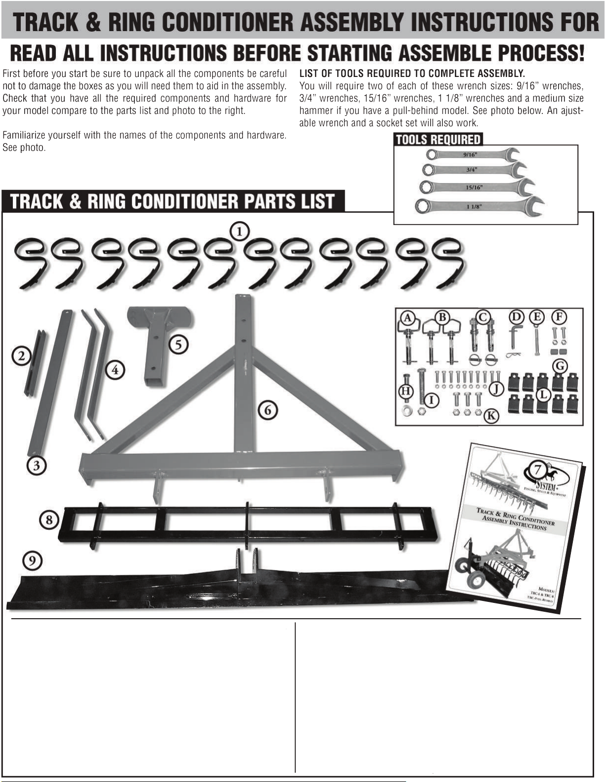
ID PART # DESCRIPTION QTY 6’ QTY 8’
1 TRC8-1 Tine Assembly with Points (6.5”) 10 12
2 TRC-HB Adjuster Bar 1 1
3 TRC-SB Straight Bar 1 1
4 TRC-SBB S-Bar 2 2
5 TRC-BP Blade Post 1 1
6 TRC-AF A-Frame 1 1
7 Assembly Manual 1 1
8 TRC-TB5 Tine Bar 5’ 1 1
8.1 TRC-TB7 Tine Bar 7’
9 TRCBLADE6 Blade 6’ 1 1
9.1 TRCBLADE8 Blade 8’
ID PART # DESCRIPTION QTY 6’ QTY 8’
A TRC-P3/4 3/4” x 4 1/4” Hitch Pin for Blade Angle Adjustment 2 2
B TRC-P3/4 3/4” x 4 1/4” Hitch Pin for 3 Point Hitch 1 1
C TRC LIFT PIN Lift Arm Pin Cat I 7/8” x 5 1/2” 2 2
D TRC-P1/2 Pin 1/2 with Clip 1 1
E 02-2137 Hex Bolt 1/2” x 4” Hot Dipped Galv G5 with Lock... 1 1
F 02-2125 Hex Bolt 1/2” x 1 1/2” Hot Dipped Galv G5 with... 2 2
G TRC-S1 Spacer 1” 2 2
H 02-2157 Hex Bolt 3/4” 4 1/2” Hot Dipped Galv G5 1 1
I 02-2158 Hex Bolt 3/4” x 5” Zinc G5 with Lock Nut 1 1
J 02-2111 Hex Bolt 3/8” x 1 1/2” Hot Dipped Galv G5 with... 10 12
K 02-2147 Hex Bolt 5/8” 2” Zinc G5 with Lock Nut 3 3
L TRCTINE Tine Brackets 10 12
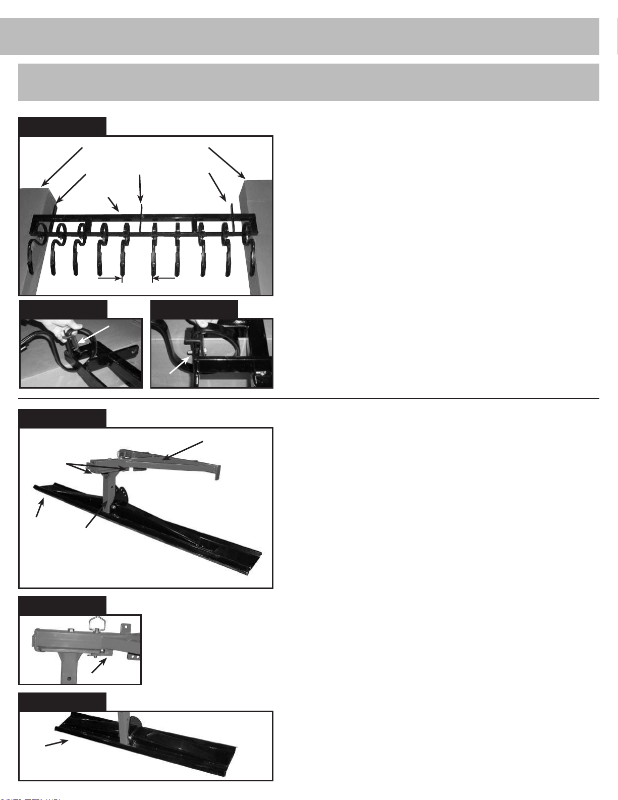
STEP 1
TRACK & RING CONDITIONER ASSEMBLY INSTRUCTIONS
STEP 1
TINE BAR ASSEMBLY
Box top & bottom used as supports
INSTALLING TINES ON TINE BAR
See fig. STEP 1 photo before proceeding.
Tine bar assembly mounting brackets
Tine Bar
Tines at spaced at 6” for TRC-6 or 7” for TRC-8
FIG 1A
Tine
Clamp
Tine
Clamp Bolt
STEP 2
Blade
Post
Guides
BLADE POST & BLADE
FIG 1B
A-frame
1. Place tine bar between two supports as shown in STEP 1 photo (we used
the top and bottom of the shipping boxes anything that will give you at least
8” clearance will do.)
2. Place first tine on tine bar as shown in FIG 1A & FIG 1B. Attach and tighten
using 3/8” x 1 1/2” bolts and lock nuts. Repeat process until all tines are in
place.
NOTE: Tines should be spaced approximately 6” apart on center for the TRC-6
and 7” for a TRC-8.
THIS FINISHED SECTION WILL BE CALLED THE TINE BAR ASSEMBLY.
STEP 2
ATTACHING THE BLADE POST AND BLADE TO THE A-FRAME
See STEP 2 photo before proceeding
1. Position the blade post in the guides on the rear of the A-frame with blade
angle adjustment holes facing towards the front of the A-frame as shown
.
FIG 2A
Blade
FIG 2A
FIG 2B
Blade
Blade
Post
Blade post guides
2. Using a 3/4” x 4 1/2” bolt put flat washer on bolt and put bolt through AFrame hole sliding into top of centre Blade Post hole. Tighten using 1 1/8”
wrench or ratchet & socket. NOTE: There is a nut is welded on to bottom
side of Blade Post Plate. (Make sure that the front hitch pin is in front hole
so Blade Post does not turn.)
3. Tighten the bolt and nut completely and then back off 1/4 turn to allow for
movement of the blade post.
4. Then drop in the 3/4” drop pin through the A-frame into a blade post adjust
ment hole. Next position the blade face down and lift the blade post and
A-frame placing it into the slot on the back of the blade, and attach using the
3/4” x 5” bolt and lock nut FIG 2
turn to allow for movement. NOTE: leave blade assembly unfinished at this
time this will make the unit more stable for the rest of the assembly.
B. Again tighten completely and back off 1/4
-
 Loading...