

System Equine Standard Stall Series, Rockwood Stall Series Assembly And Installation Instructions Manual
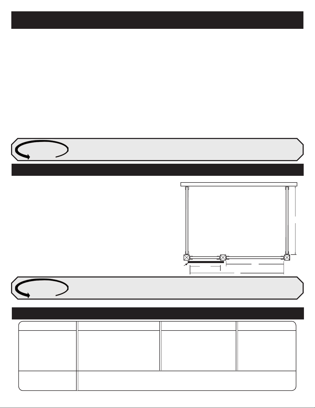
Outside Wall of Building
Door Post
Side Wall
DFig. A
C
A
B
Side Wall
Corner PostCorner Post
Stall Door
BEFORE YOU START
NOTE: All measurements are based on finished wood sizes. Example 2” x 6” finished size is 1 1/2” x 5 1/2”
Questions to Be Answered…
Careful consideration when designing your barn layout will save you time, money and frustration.
Do you want the horses to see one another?
Solid partition walls
Grilled partition walls
Privacy partition walls
Do you want to have the horses look out the front of the
stalls?
Flip down V- doors
Swing out feed doors
Shutter doors
Swing Down doors
Do you want to be able to feed from outside the stall?
Swing out feed doors
Feed Opening
Standard Stall Sizes are 10’x10’, 12’x12’, 10’x12’ Make sure to plan for additions to your stable ahead
SY S T E M TI P
of time. System Standard Stalls feature options such as removable walls, feed doors, V-Doors & more.
ANY SIZE STALL CAN BE BUILT USING THE SYSTEM STALL SYSTEM
What type of latch do you like?
Slide latch
Top latch catch
Horseshoe Latch
What type of wood are you using?
1 1/2" width is the standard thickness of the
U-Channel.
Are you concerned with good ventilation?
Grilled Front Walls
Grilled side walls
Full Grill doors
1. Corner posts can be set 10' or 12' (or any other spacing as
desired) on center to fit building design or special needs. The
Grill length (See C in fig A) of a standard 10’ stall front is 65” and
91” for a 12’ stall front. (See Fig. A). However, grill sections can
be combined to create any size of stall front you desire.
2. The inside distance between the door posts (See B in fig A) must
be 48". Posts used for the installation may be 6X6, 4x4, or 4X6.
If top of posts are not going to be anchored then a sufficient
amount of post should be placed deep enough in the footing to
provide adequate holding power. (We recommend a 3’ depth)
3. Install the corner posts first followed by the door posts. Make
sure all posts are plumb, true and level.
Keep in mind the finished size for 2” x 6” dressed lumber is 1 1/2” x 5 1/2”. If choosing tongue & groove as your
SY S T E M TI P
filler wood take in to account the loss of height due to the tongue & grooves. We recommend you use pressure
treated wood for the bottom two boards of your stall system.
NOTE: Wall sections that span over 12’ long will require a 4” x 4” center support post.
WOOD SPECS FOR SYSTEM STALL SYSTEMS
SECTION 10 FT. STALL 12 FT. STALL 14 FT. STALL
Front walls
(for header channel)
Grill Partitions
Solid Partitions
10 - 2” X 6” X 10’
1 - 2” X 10” X 10’
9 - 2” X 6” X 10’
1 - 2” X 10” X 10’
18 - 2” X 6” X 10’
10 - 2” X 6” X 12’
1 - 2” X 10” X 12’
9 - 2” X 6” X 12’
1 - 2” X 10” X 12’
18 - 2” X 6” X 12’
10 - 2” X 6” X 14’
1 - 2” X 10” X 14’
9 - 2” X 6” X 14’
1 - 2” X 10” X 14’
18 - 2” X 6” X 14’
Posts* 4X4
4X6
6X6
Standard Stall Instructions 2011 - Page 2
3 Needed per stall system except when stalls are added next to each other.
*See Fig. A above.
STEPS TO EASY INSTALLATION...
POST INSTALLATION
When you auger posts, all posts should be installed with the top at least 8’ above the ground. If the
SY S T E M TI P
NOTE: Post can be installed in several ways. The most common is to auger into the ground and using post anchoring plates.
posts are not properly secured at the top, they must be buried to a depth of at least 3’ to provide
adequate stability.
STEP 1
Refer to Fig. A page 2 to determine post locations for the size of stall
that has been selected.
STEP 2
Install the corner posts first, being careful to stay within the distances
A and D as given in the chart.
STEP 3
Install the door post to distance B to a tolerance of + or - 1/4”.
NOTE: Make sure all posts are checked for level on all sides.
STEP 4
Dimension C should be treated as the variable dimension if a problem
with post location should arise. In this event, it may be necessary to
cut some of the grill components.
CHECKING FOR SQUARE: Measure from one corner diagonally to the opposite corner (top left to bottom
SY S T E M TI P
right) and repeat for the other corner, measurements should be the same. If they are not, tap the corner of
the longest measurement until you have two equal measurements. This will ensure your work is square.
FRONT WALL ASSEMBLY
STEP 1 (See Fig. 1B, on page 5)
1a. Install the 46" U-channels on the corner and door posts with the
screws provided. (channels under grillwork)
1b. U-channels should be set back 1/2" from the front face of the posts.
1c. The U-channels should be set + or - 1/2" above the floor.
STEP 2
Cut all necessary lumber to a length 1/4" to 3/8" less than the distance
measured between the inside faces of the U-channel.
STEP 3
Installing the lumber in the U-channels.
3a. Slide the first board down to the bottom of the U-channel ensuring
that it is level. (pressure treated lumber can be used for the bottom
of the stall wall)
3b. Firmly secure the bottom board with the screws provided before
installing the remaining boards.
STEP 4
Install all remaining boards ensuring that they come to a height of 1 1/8"
above the top of the U-channels. It may be required to rip cut a board to
achieve the correct height.
STEP 5
Install the rubber grommets as shown in Detail D on page 5 for both the
bottom and top grill channels.
STEP 6
Install the bottom grill channel flush with the top of the U-channels, secure
STALL ARRANGEMENTS USING 3 1/2”X 3 1/2” POSTS
10’ STALL FRONT
A = 116.5”
B = 48”
C = 65”
D = 120”
12’ STALL FRONT
A = 142.5”
B = 48”
C = 91”
D = 144”
With all posts in place it is time
SY S T E M TI P
to order your lumber and unpack
the stall components. Review the
assembly drawing to familiarize
yourself with the names and locations of the parts. Try not
to mix boxes.
TO AVOID MISTAKES PERFORM EACH STEP IN THE
SEQUENCE SHOWN.
the channel with the screws provided.
STEP 7
At a height 36 3/8" install two 7" header U-channels above the top of the
46” U-channel.
STEP 8
Place the 2” x 10” header board in the 7” U-channels allowing it to extend
1/2” bellow the 7” U-channels. Use a screw at each end to hold the header
board in place for now. Put the top grill channel in position on the bottom
of the header board again hold in place with screws.
STEP 9
Insert the grill bars starting at one end. Place the grill bars in the top grill
channel then lower into the bottom grill channel, repeat until all bars are
in place. When all bars are in place remove the screws used to hold the
header board and top grill channel. Push or pull down on the header board
until it sits evenly on the top of the grill bars. Now secure the header and
top grill channel in place with the screws provided.
STEP 10
THE FOLLOWING IS FOR 12’ FRONTS OR LARGER ONLY. Install the
one wall brace placing it on the inside of the wall.
NOTE:
• 12’ Front walls come with one 46” wall brace.
• Grilled partition walls come with two 46” wall braces, 1 for each
side.
• Solid partition walls come with two 94” wall braces one for each
side.
SY S T E M TI P
There are two 7” header U-Channels provided with each stall door to install an optional 2”x10” lumber
header in the door opening for added strength. Installation instructions for Optional Header are on page 8
of this manual.
Standard Stall Instructions 2011 - Page 3
 Loading...