


Reg 10497/0604
CiS No.: 360.610.0070
V ersion 1/06.04
© Systeme Lauer GmbH & Co. KG
EPC G
Embedded PC
User Manual

© Systeme Lauer GmbH & Co. KG • Kelterstr. 59 • D-72669 Unterensingen • Tel: +49 (7022) 96 60-0 • Fax: +49 (7022) 96 60-103
0-2
Systeme Lauer GmbH & Co KG
Postfach 1465
D-72604 NürtingenGermany
User Manual: EPC G
Embedded PC
Issued: June, 2004
Author: Jung
Operating instructions, manuals and software are protected by copyright
laws. All rights reserved. Copying, duplicating, translating, or converting
these materials in whole or in part is prohibited. An exception is made in
the case of preparing a backup copy of the software for personal use.
• The manual is subject to change without prior notification.
• We cannot guarantee that the programs and data stored on the disk
are free of errors and absolutely correct.
• Since diskettes represent manipulatable data media, all we can
guarantee is that there is no physical damage to them. Liability is
limited to replacement.
• We welcome suggestions for improvements as well as pointing out
errors at any time.
• The agreements also apply to the special appendices to this manual.
Microsoft, Windows, Windows NT and the Windows Logo
are either registered trademarks or trademarks of Microsoft
Corporation in the USA and/or other countries.
Other names designated in this document may be brand
names, the use of which by third parties for their own
purposes may violate the rights of the proprietors.

© Systeme Lauer GmbH & Co. KG • Kelterstr. 59 • D-72669 Unterensingen • Tel: +49 (7022) 96 60-0 • Fax: +49 (7022) 96 60-103
0-3
Information for Users
Please read this manual before using the product for the first time, and be
sure to keep it where you can make use of it later.
Unless where explicitly referred to the versions Economy Unit or Business Unit, the description applies for all units.
Intended audience The manual has been written for users who are familiar with PC systems
and automation technology.
Conventions used in this manual [KEY] Keys the user has to press on the keyboard are
represented in square brackets, e.g. [CTRL] or [DEL].
Courier Screen output is represented in the Courier type font,
e.g. C:\>
Courier Bold User inputs via keyboard are identified
by the Courier Bold type font, e.g. C:\>DIR
Italics
The names of buttons, menus or other screen
elements the user has to select and product names
are represented in
italics
.
Safety instructions Wherever there may be dangerous faults in the automation equipment,
i.e., where an error would cause significant property damage or injury to
persons if it occurred, additional external precautions must be taken or
equipment must be set up (for example by using independent limit
switches, mechanical disabling locks, etc.). In the event of an error, these
measures must ensure or force a safe operating status.
Testing and verification of suitability for the purpose intended by the user,
or for deployment under usage conditions, are the responsibility of the
user. Systeme Lauer accepts no liability for testid.
Pictograms The following pictograms have been used in the manual to identify special
text passages:
Danger!
Potentially hazardous situation.
May result in personal injury.
Caution!
Potentially hazardous situation.
May result in property damage.
Tips and supplementary information

© Systeme Lauer GmbH & Co. KG • Kelterstr. 59 • D-72669 Unterensingen • Tel: +49 (7022) 96 60-0 • Fax: +49 (7022) 96 60-103
0-4
Table of Contents
Information for Users 0- 3
T able of Contents 0- 4
Company 0-5
Contact 0-6
1 Product Description 1- 1
1.1 Control side ..................................................................... 1-1
1.1.1 EPC G Touch .......................................................... 1-1
1.1.2 EPC G Key ............................................................. 1-1
1.2 Rear side .......................................................................... 1-2
2 Commissioning 2-1
2.1 Po wer suppl y................................................................... 2-1
2.2 Grounding diagram......................................................... 2-2
2.3 Installation ....................................................................... 2-2
T T echnical data T-1
T1 Mechanical dimensions ...................................................T-1
T1.1 EPC G 1000 Outer/Mounting dimensions .................T-1
T1.2 EPC G 1000 Unit dimensions...................................T-2
T1.3 EPC G 1200 Outer/Mounting dimensions .................T-3
T1.4 EPC G 1200 Unit dimensions...................................T-4
T1.5 EPC G 1500 Outer/Mounting dimensions .................T-5
T1.6 EPC G 1500 Unit dimensions...................................T-6
T1.7 EPC G 1500 V2A Outer/Mounting dimensions .........T-7
T1.8 EPC G 1500 V2A Unit dimensions ...........................T-8
T1.9 EPC G 1000k Outer/Mounting dimensions ..............T-9
T1.10 EPC G 1000k Unit dimensions...............................T-10
T1.11 EPC G 1200k Outer/Mounting dimensions ............. T-11
T1.12 EPC G 1200k Unit dimensions...............................T-12
T2 Electrical data ................................................................. T-13
T3 Ambient conditions........................................................ T-14
T4 Interfaces ........................................................................T-15
T4.1 Compact-FLASH-Slot............................................. T-15
T4.2 VGA/COM Interface ............................................... T-15
T4.3 Ethernet, USB, PS/2 .............................................. T-16
T4.4 Cassette option ...................................................... T-16

© Systeme Lauer GmbH & Co. KG • Kelterstr. 59 • D-72669 Unterensingen • Tel: +49 (7022) 96 60-0 • Fax: +49 (7022) 96 60-103
0-5
Company
Elektronik-Systeme LAUER GmbH & Co . KG
Kelterstraße 59
D-72669 UnterensingenGermany
T el. +49 (7022) 9660-0
Fax. + 49 (7022) 9660-274
Our philosophy Systeme LAUER is a reliab le partner who thinks and acts internationally.
From the LCA electronic te xt display and the high-tech PCS control panel
to the industrial computer we supply a complete program for
• operation
• monitoring and
• control
Within the AUGUSTA T echnologie AG, a g roup of global companies, Systeme LAUER stands for an almost unlimited product range right up to
competent service.
On account of an active cooperation with our customers, our qualified
team produces convincing concepts which bring man, machine and
interface into line in an efficient wa y.
Proximity to our customers – the direct dialog – is the foundation of our
success.

© Systeme Lauer GmbH & Co. KG • Kelterstr. 59 • D-72669 Unterensingen • Tel: +49 (7022) 96 60-0 • Fax: +49 (7022) 96 60-103
0-6
Contact
Support Telephone: +49 (7022) 9660–209
E-mail: support@systeme-lauer.de
In case of support enquiries, please have the serial number of the
device ready !
Please access our Download Forum to find current drivers, software,
drivers, manuals, … and novelties at
http://forum.systeme-lauer.de/
Sales Telephone: +49 (7022) 9660-0
E-mail: Sales@systeme-lauer.de
In addition, we offer ... training and technical courses in our modern training center, or, if you
prefer, in your company.
Ask your sales partner for our current training catalog.
... not only demonstration units, but we also provide specialists who
assist you personally when starting your first application.

© Systeme Lauer GmbH & Co KG • Kelterstr.59 • 72669 Unterensingen • Tel. (07022) 96 60-0 • Fax (07022) 96 60-103
1-1
1 Product Description1 Product Description
1.1 Control side
1.1.1EPC G Touc h
1 Color TFT -Display
10,4“, 12,1“ or 15“ with
Resistiv T ouch
1.1.2EPC G Key
2 Color TFT -Display
10,4“ with Resistiv Touch
3 Color TFT -Display
12,1“ with Resistiv Touch
1
2
3

© Systeme Lauer GmbH & Co KG • Kelterstr.59 • 72669 Unterensingen • Tel. (07022) 96 60-0 • Fax (07022) 96 60-103
1-2
1 Product Description
4 Color TFT -Display
15 “ with Resistiv Touch
5 Front plate V2A
1.2 Rear side
6 COM 1 / COM 2
7 VGA
8 PS/2 Mouse / PS/2 keyboard
9 USB 1 / 2
aJ LAN 1 / 2
aA Grounding screw
aB Pow er supply
aC Compact Flash
4
6
7
89aJ
aA
aB
aC
5

© Systeme Lauer GmbH & Co KG • Kelterstr.59 • 72669 Unterensingen • Tel. (07022) 96 60-0 • Fax (07022) 96 60-103
2-1
2 Commissioning2 Commissioning
2.1 Power supply
Caution!
The EPC G must only be operated at protective extra-low-voltage as
defined by European standard EN60950!
The control transformer must comply with European standard EN60742!
Compare the power supply voltage with the v oltage specified on the type
label.
All cable connections must be tested before commissioning the system.
You must ensure that all the voltages and signals correspond to the rele-
vant specifications.
1 24 V power supply
2 Grounding screw
The power supply is rendered by a two-pole connector (Phoenix MST BT
2.5/2).
Pow er supply diagram
230 V AC
+ 24 V
230 V AC
0 V
24 V DC
1
2

© Systeme Lauer GmbH & Co KG • Kelterstr.59 • 72669 Unterensingen • Tel. (07022) 96 60-0 • Fax (07022) 96 60-103
2-2
2 Commissioning
2.2 Grounding diagram
In order to ensure a safe diversion of electric interferences ,
the following points hav e to be observed:
• Connect the device and the switch cabinet with a centr al grounding
point via the shortest route possible.
• Make sure the connection between the device and switch cabinet
has the lowest inductivity possible .
• All the data cables connected to the device must be shielded cables .
• The shields must be grounded on both the ends. Connections
between systems must be of low impedance. High transient currents
over the line shield resulting from differences in potential must be
excluded.
• The design of the grounding connection with green/yellow cable must
have a cross section of at least 4 mm².
2.3 Installation
Installation The device should be installed in an HF-proof housing or switch cabinet
made of metal.
To ensure that heat generated in the device can dissipate into the
environment, a space of 100 mm must be maintained around the device!
Eight hexagon nuts are used f or assembly (depending upon ex ecution of
the equipment).
Tip!
The equipment may not be inserted lying, since otherwise convection at
the radiator box is not ensured. Max. inclination to the rear 20°.
Caution!
Potential hazard of damaging the de vice!
Front-side protection type IP65 is only guaranteed if the seal is correctly
seated in the front plate.

© Systeme Lauer GmbH & Co KG • Kelterstr.59 • 72669 Unterensingen • Tel. (07022) 96 60-0 • Fax (07022) 96 60-224
T-1
T Technical dataT Technical data
T1 Mechanical dimensions
Free spaces To ensure that heat generated in the device can dissipate into the
environment, a space of 50 mm must be maintained around the device!
T1.1 EPC G 1000 Outer/Mounting dimensions
Front plate Width 318 mm
Height 244 mm
Cutout dimensions Width 303 mm
Height 228 mm
Mounting depth 119,5 mm.
Weight approx. 5,5 kg
T ype of attachment:
With 6 retaining blocks made of
aluminum or plastic with M5x30,
DIN 914 set screws,with tip and
hexagon socket, galv anized.

© Systeme Lauer GmbH & Co KG • Kelterstr.59 • 72669 Unterensingen • Tel. (07022) 96 60-0 • Fax (07022) 96 60-224
T-2
T Technical data
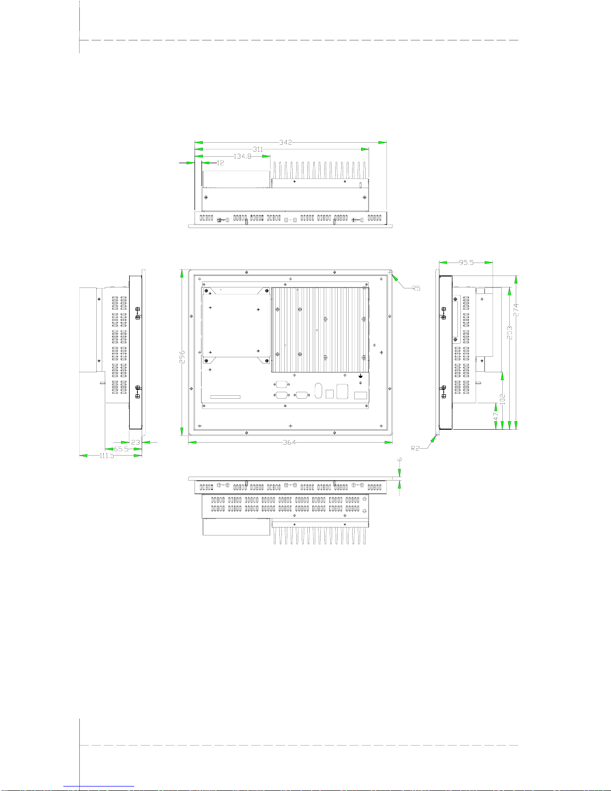
T1.2 EPC G 1000 Unit dimensions
Bottom view of device
Side view Rear view of device Side view
Top view of device

© Systeme Lauer GmbH & Co KG • Kelterstr.59 • 72669 Unterensingen • Tel. (07022) 96 60-0 • Fax (07022) 96 60-224
T-3
T Technical data
T1.3 EPC G 1200 Outer/Mounting dimensions
Front plate Width 364 mm
Height 296 mm
Cutout dimensions Width 345 mm
Height 277 mm
Mounting depth 111,5 mm.
Weight approx. 6,0 kg
Type of attachment:
8 pieces of nut/mother M4,
8 pieces of wearing parts M4 and
8 pieces of toothed washers M4.
8x Bohrhole Ø 4,6 mm
© Systeme Lauer GmbH & Co KG • Kelterstr.59 • 72669 Unterensingen • Tel. (07022) 96 60-0 • Fax (07022) 96 60-224
T-4
T Technical data
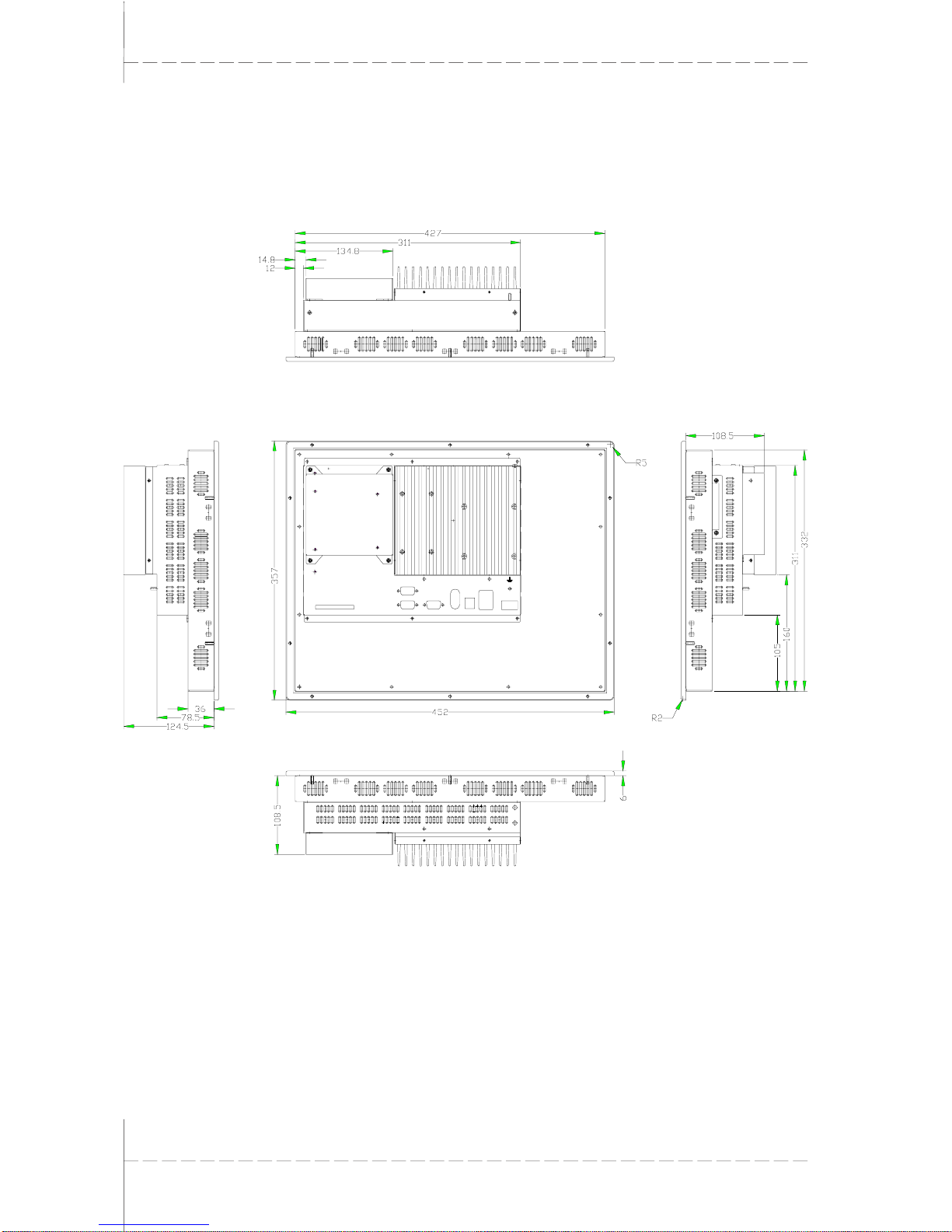
T1.4 EPC G 1200 Unit dimensions
Bottom view of device
Side view Rear view of device Side view
Blick auf die Geräteoberseite

© Systeme Lauer GmbH & Co KG • Kelterstr.59 • 72669 Unterensingen • Tel. (07022) 96 60-0 • Fax (07022) 96 60-224
T-5
T Technical data
T1.5 EPC G 1500 Outer/Mounting dimensions
Front plate Width 452 mm
Height 357 mm
Cutout dimensions Width 429 mm
Height 334 mm
Mounting depth 124,5 mm
Weight approx.76,5 kg
Type of attachment:
10 pieces of nut/mother M4,
10 pieces of wearing parts M4 and
10 pieces of toothed washers M4.
10x Bohrhole Ø 4,6 mm
© Systeme Lauer GmbH & Co KG • Kelterstr.59 • 72669 Unterensingen • Tel. (07022) 96 60-0 • Fax (07022) 96 60-224
T-6
T Technical data
T1.6 EPC G 1500 Unit dimensions
Bottom view of device
Side view Rear view of device Side view
Top view of device

© Systeme Lauer GmbH & Co KG • Kelterstr.59 • 72669 Unterensingen • Tel. (07022) 96 60-0 • Fax (07022) 96 60-224
T-7
T Technical data
T1.7 EPC G 1500 V2A Outer/Mounting dimensions
Front plate Width 407 mm
Height 316 mm
Cutout dimensions Width 393 mm
Height 303 mm
Mounting depth 126 mm
Weight approx. 7,0 kg
T ype of attachment:
With 8 retaining blocks made of
aluminum or plastic with M5x30,
DIN 914 set screws,with tip and
hexagon socket, galv anized.

© Systeme Lauer GmbH & Co KG • Kelterstr.59 • 72669 Unterensingen • Tel. (07022) 96 60-0 • Fax (07022) 96 60-224
T-8
T Technical data
T1.8 EPC G 1500 V2A Unit dimensions
Bottom view of device
Side view Rear view of device Side view
Top view of device

© Systeme Lauer GmbH & Co KG • Kelterstr.59 • 72669 Unterensingen • Tel. (07022) 96 60-0 • Fax (07022) 96 60-224
T-9
T Technical data
T1.9 EPC G 1000k Outer/Mounting dimensions
Front plate Width 410 mm
Height 266 mm
Cutout dimensions Width 387 mm
Height 243 mm
Mounting depth 120 mm.
Weight approx. 6,5 kg
T ype of attachment:
With 8 retaining blocks made of
aluminum or plastic with M5x30,
DIN 914 set screws,with tip and
hexagon socket, galv anized.

© Systeme Lauer GmbH & Co KG • Kelterstr.59 • 72669 Unterensingen • Tel. (07022) 96 60-0 • Fax (07022) 96 60-224
T-10
T Technical data
T1.10 EPC G 1000k Unit dimensions
Bottom view of device
Side view Rear view of device Side view
Top view of device

© Systeme Lauer GmbH & Co KG • Kelterstr.59 • 72669 Unterensingen • Tel. (07022) 96 60-0 • Fax (07022) 96 60-224
T-11
T Technical data
T1.11 EPC G 1200k Outer/Mounting dimensions
Front plate Width 483 mm
Height 310 mm
Cutout dimensions Width 452 mm
Height 292 mm
Mounting depth 114,5 mm
Weight approx. 7,0 kg
T ype of attachment:
With 10 retaining blocks made of
aluminum or plastic with M5x30,
DIN 914 set screws,with tip and
hexagon socket, galv anized.

© Systeme Lauer GmbH & Co KG • Kelterstr.59 • 72669 Unterensingen • Tel. (07022) 96 60-0 • Fax (07022) 96 60-224
T-12
T Technical data
T1.12 EPC G 1200k Unit dimensions
Bottom view of device
Side view Rear view of device Side view
Top view of device

© Systeme Lauer GmbH & Co KG • Kelterstr.59 • 72669 Unterensingen • Tel. (07022) 96 60-0 • Fax (07022) 96 60-224
T-13
T Technical data
T2 Electrical data
Pow er supply Operating voltage 24 V ± 15 %, protected against reverse
polarity
Po wer consumption approx. 2 A
Display EPC G 1000
TFT-Display 800 x 600 Pixel, 65536 colors, 10,4“, CFL background
illumination
EPC G 1200
TFT-Display 800 x 600 Pixel, 65536 colors, 12,1“, CFL background
illumination
EPC G 1500
TFT-Display 1024 x 768 Pixel, 16 Mio. colors, 15“, CFL background
illumination
Operating temperature r ange 0 ... 45 °C
Touch Resistive
CPU Processor 1 GHz VIA C3
Ram 256 MB
Chipset VIA PN 133T, integrated Graphic
Memory card (external) 32 MB, 64 MB, 128 MB, 256 MB , 512 MB
Slots PC 104
Interfaces Serial 2 x RS 232
USB 2 x USB 1.1
Keyboard/Mouse 2 x PS/2
Network 2 x 10/100 Mbit
Monitor 1 x VGA

© Systeme Lauer GmbH & Co KG • Kelterstr.59 • 72669 Unterensingen • Tel. (07022) 96 60-0 • Fax (07022) 96 60-224
T-14
T Technical data
T3 Ambient conditions
Ambient temperature Operation in case of vertical (standing) installation 0...45°C
Storage -20 ... 60° C
Humidity Operation/Storage 10 ... 95 %, non-condensing
Resistance to vibration and shock Sine 2 g, 10-500 Hz
Shock 15 g, 11 ms
Continuous shock 10 g, 16 ms
Free f all from a height of 1 m (in packaging)
Protection type Front IP 65
Rear side IP 20
EMC/CE Interference resistance European standard EN 61-000-6-2
Interference emission European standard EN 55022

© Systeme Lauer GmbH & Co KG • Kelterstr.59 • 72669 Unterensingen • Tel. (07022) 96 60-0 • Fax (07022) 96 60-224
T-15
T Technical data
T4 Interfaces
T4.1 Compact-FLASH-Slot
In its standard configuration, the EPC devices are equipped with a
Compact FLASH slot based on CFA standard (Type 1).
Position of Compact-FLASH-Slots
1 Ejection lever
Caution!
Compact FLASH cards manufactured by SANDISK only ma y be used in
combination with the EPC!
The compact FLASH card may be changed only when the device has
been switched off !
T4.2 VGA/COM Interface
1 VGA-Port
2 COM 1 / 2
The serial interface has been assigned according to the PC XT/AT
standard!
1
1
2

© Systeme Lauer GmbH & Co KG • Kelterstr.59 • 72669 Unterensingen • Tel. (07022) 96 60-0 • Fax (07022) 96 60-224
T-16
T Technical data
T4.3 Ethernet, USB, PS/2
1 Ethernet 1 / 2 (RJ45)
2 USB 1 / 2
3 PS2 Mouse/Keyboard
Caution!
The PS/2 mouse and PS/2 keyboard ma y be plugged or unplugged only
when the device is switched off.
Otherwise these input devices are not recognized b y the operating system!
A maximum current of 100 mA may be dra wn from the two USB interfaces!
External USB devices which require a higher supply current have to
provide this current themselves!
T4.4 Cassette option
1 Bus module cassette (opt.)*
* Depending on the type of bus
module, the interfaces can v ary.
If the bus module cassette has
not been fitted, the rear side of
the device is covered with a co v er
sheet.
2
13
1
 Loading...