

Version 13 (08.2018. EN)
MANUAL
S2

Version 13 (08.2018. EN) (S2)
Page 2 of 48
General
For safety during installation and later use it is very important that installation, operating and maintenance
instructions are carefully followed.
You are requested to keep this instruction manual at a location where it will be available at all times, and it should be
submitted to the person who is responsible for this product. In the event that the instruction manual is lost, you are
welcome to order a new one from your dealer.
If any doubt should arise with regard to the content of these instructions, please contact the distributor.
Proper use
System Cleaners’ system is exclusively designed to transport and pressure-increase of water to satellite stations. All
other forms of application or use not within the scope of the above are considered to be improper and inconsistent
with the requirements and regulations, and may lead to hazardous situations.
System Cleaners A/S cannot be held liable for consequential damage resulting from improper use of the equipment.
Proper use includes the following:
The instructions, regulations and recommendations concerning the system stated in the instruction manual
Observance of the specified inspection and maintenance intervals
Correct maintenance of good operating condition of the system
Observance of the specified environmental and operating conditions
Proper use also includes observance of all information that is stated in this instruction manual. This applies in
particular to the specified safety instructions.
Liability
Each user must handle and use the system in a responsible manner.
It is therefore of great importance that this instruction manual is available to the sanitation employee concerned at all
times.
Safety
The design of the system complies with generally accepted technical regulations and provisions concerning the working
environment and accident prevention. Despite this, risks can occur during use that can lead to physical inconvenience
for the user or a third party or have an impact on the machine or other equipment.
The system must therefore be in prime technical condition before use and may only be used in accordance with its
purpose and with strict observance of the safety requirements and operating instructions. In particular, malfunctions
and irregularities that can affect safety must be remedied immediately.
Warranty
For a period of 24 months from the date of delivery, your dealer will honor a warranty on parts that do not function
properly due to material defects or manufacturing faults. The warranty does not cover wearing parts. The warranty will
cover replacement or repair of the defective part. Costs with regard to dismantling, forwarding and reassembly are
defrayed by the purchaser. Any return shipments from System Cleaners A/S following completed repairs are defrayed
by System Cleaners A/S. The defective parts remain the property of System Cleaners A/S.
Claims that may be made for legal reasons, ordinary wear and tear, as well as damage to parts that can be attributed
to negligent or improper handling are not covered by the warranty. The warranty will be void if the system has been
exposed to frost. The warranty will also be void if modifications or repairs have been carried out by unauthorized
personnel. Warranty claims will only be accepted if they are reported to System Cleaners A/S immediately after
damage has been discovered. The warranty is terminated if there is a change of ownership of the machine. System
Cleaners A/S and its dealers cannot be held liable for personal injury, damage to equipment, loss of earnings,
including production losses, losses to stock or similar that may have arisen as a result of defects or delayed delivery of
the sold product, irrespective of the cause, including manufacturing faults or material defects. In addition, please refer
to our general terms and conditions of sales and delivery.

Version 13 (08.2018. EN) (S2)
Page 3 of 48
Disposal
Please be aware of the following applicable provisions: the equipment must be disposed of according to its nature and
applicable requirements, e.g. electrical scrap, synthetic material, stainless steel, brass, etc.
Labelling
The system is equipped with a type plate containing technical data.
The type plate is located on a fixed part of the system.
Declaration of conformity
We declare that this product is in conformity with the following directives:
2006/42/EC Directive on Machinery
Per Kjøller
Development Manager
Version 13 (08.2018. EN) (S2)
Page 4 of 48
DESCRIPTION
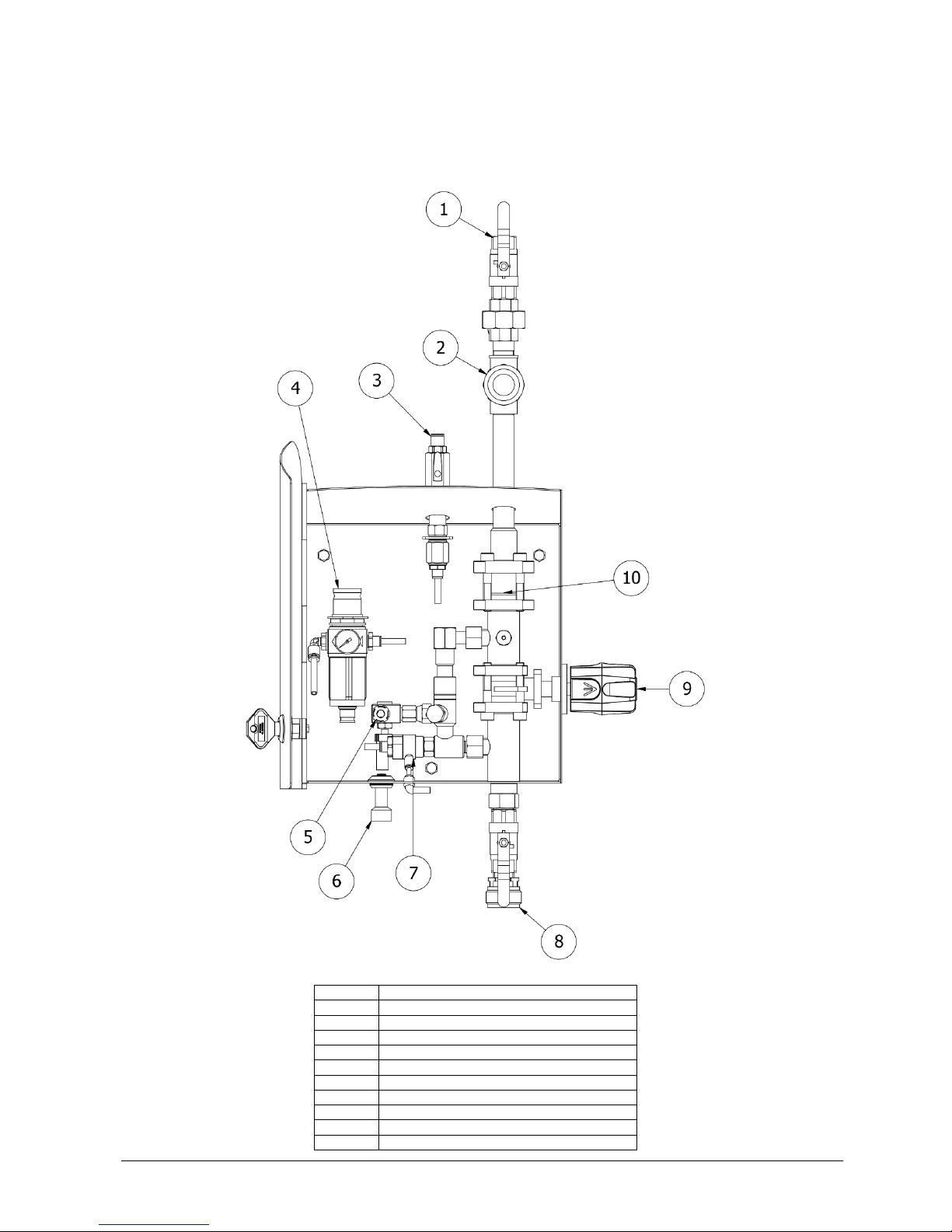
Satellite
A satellite is connected to pressurized water, a number of chemicals and, depending on the model, compressed air.
Using a satellite it is possible for one operator to rinse, foam or disinfect (depending on model).
Pos.
Description
1
Inlet water
2
Strainer
3
Inlet air
4
Air regulator
5
Dosing valve chemical
6
Suction tube chemical
7
Air unit
8
Outlet
9
Function selector
10
Injector system

Version 13 (08.2018. EN) (S2)
Page 5 of 48
INSTALLATION
Storage
The machine must not be exposed to frost unless it has been emptied of water (frost protected). Even brief periods of
exposure to frost may cause damage to the equipment.
Store the equipment in a frost-free room in the original packing.
Installation
Place the equipment in a frost-free room, well protected from the sun and place it on a hard surface.
Make sure that, in the event of failing non-return valves in the air and water supply, there are suitable back-flow
preventers fitted.
Local regulations may require installation of a back-flow protecting device to prevent compressed air or chemicals
getting into the water supply.
Piping
The piping should be made from materials suitable for the media in the pipes, the maximum pressure and
temperature.
It is the fitter’s responsibility to ensure that the piping including all armatures conform to local regulations.
The installation must be performed such that forces from pipes etc. are not transferred to the equipment during and
after fitting, as this may result in leaks or damage the equipment.
Select a pipe size so that the flow velocity in the pipe is up to 3 meters/second (10 feet/second). This gives a normally
accepted pressure loss and low noise from the flow.
In order to facilitate maintenance of the equipment, it is recommended to fit a shut-off valve in the pipelines
immediately at the connections for water.
Pipe supports
Always use pipe supports designed for the pipe size and material and maximum working pressure and temperature.
Version 13 (08.2018. EN) (S2)
Page 6 of 48

Version 13 (08.2018. EN) (S2)
Page 7 of 48
COMMISSIONING
Flushing
Pipes etc. must be flushed efficiently before connecting the unit.
Before commencing operation on the unit or following repair work, the unit must be flushed thoroughly to remove any
impurities or foreign bodies.
Disinfection
Local specifications may require disinfection of the wetted parts like internals of pipes and pumps before use to avoid
contamination of newly cleaned surfaces.
Dosing
Adjust the dosing according to the chemical supplier’s recommendations.
Always calibrate and, if required, document the dosing on a regular basis.
Air
Adjust the air pressure until a satisfactory foam quality is achieved.
Note that good foam quality depends on the mixture of water, chemical and air and getting a perfect result requires
some adjustments of the mixing ratios.
OPERATION
Safety
It is recommended that suitable working clothes be worn. For protection against certain types of detergents, always
use protective goggles, respiratory protective equipment and rubber gloves.
It is recommended that non-slip footwear be worn since the floor can be slippery due to the presence of water and
foam.
This system may only be operated, maintained and – not least - repaired by persons who are familiar with the system
and properly trained to carry out the job concerned.
It is the customer’s responsibility that these installation and operating instructions are supplemented by in-house
instructions concerning inspection and reporting, industrial management, personnel training, etc.
Do not carry out any work if you are unsure of the consequences or are insufficiently skilled to carry it out. If in doubt,
you should contact your superior or your agent in advance.
Never direct the water jet at other persons.
Never direct the water jet at electrical installations.
Check that couplings “lock” when hoses and nozzles are fitted. If possible, practise this procedure before operation.
Always relieve the pressure in the rinsing hose by opening the low-pressure gun or valve after the water supply has
been shut off before dismantling the couplings and removing the hose.
During operation of the system, ensure that the low-pressure gun/valve is closed before releasing the handle.
When the low-pressure gun or valve is opened, the water jet will result in a certain amount of counter-pressure.
Therefore make sure that you hold the handle firmly and have a firm foothold.
System Cleaners low-pressure systems may only be used in conjunction with soaps and chemicals that are approved
for cleaning within the food or transport industries.
Soaps and chemicals that are classified as highly corrosive, toxic or which pose a health risk to humans or animals
may not be used.

Version 13 (08.2018. EN) (S2)
Page 8 of 48
The system must not be used together with solvents or volatile liquids that pose a health risk or are inflammable.
In the event that the system is used with non-approved soaps, chemicals or solvents, System Cleaners A/S disclaims
all liability.
If in doubt, please contact your soap or chemical supplier and read the supplier manual.
In the event that you use the system with chemicals that require mandatory labelling, or if the water temperature
exceeds 50°C, a low-pressure gun with an automatic closing device must be used.
In the event that you use the system without a gun with an automatic closing device together with chemicals that
require mandatory labelling, or water with a temperature that exceeds 50°C, System Cleaners A/S disclaims all
liability.
Pressure relief
After use shut the isolating valves over the equipment and relieve air and water pressure in hoses etc.
Flush injector system
After each use flush the injector system with warm water to avoid clogging of the injector.
MAINTENANCE
Water filter
Depending on the mains water quality it may be necessary to clean the water filter on a regular basis to prevent the
pump from stopping.
Water non-return valve
Water non-return valves are critical wear parts and should be replaced yearly.
Air filter
Depending on the quality of the compressed air it may be necessary to empty condensation collected in the air filter
bowl on a regular basis.
Injector system
The injector system consists of foot strainer, dosing valve, non-return valve and injector.
Chemical residues compromises the function of the injector and flushing with warm water after each use is required to
maintain trouble free operation.
Depending on the water quality it may be necessary to de-scale the water side of the injector on a regular basis
following the chemical supplier’s guidelines.
Version 13 (08.2018. EN) (S2)
Page 9 of 48
TROUBLE SHOOTING
Fault
Cause
Remedy
No water or insufficient water at the
nozzle when rinsing
Function selector is in closed
position
Turn the function selector switch to the
desired function
Insufficient water supply to the unit
Make sure that the water supply is as
described in the technical specifications
Valve at the end of the hose not
open
Open valve
The unit does not suck up detergent
Function selector is not in the
correct position
Turn function selector switch to desired
function
Suction filter or chemical restrictor
are blocked by chemical residue
Clean suction filter or chemical
restrictor
Water pressure is too low
Make sure water supply is as
described in the technical specifications
Suction filter is above the fluid level
in chemical container
Position the suction filter below fluid level
Poor foam quality
Chemical product is not a foaming
product
Change to a foaming chemical
Incorrect dosing
Adjust the dosing according to chemical
supplier’s specifications
Suction filter or chemical restrictor
are blocked by chemical residue
Clean the suction filter or chemical
restrictor
Water pressure is too low
Make sure that the water supply is as
described in the technical specifications
Air pressure too low
Increase air pressure
Non-original foam nozzle fitted
Replace with original white foam nozzle
Version 13 (08.2018. EN) (S2)
Page 10 of 48
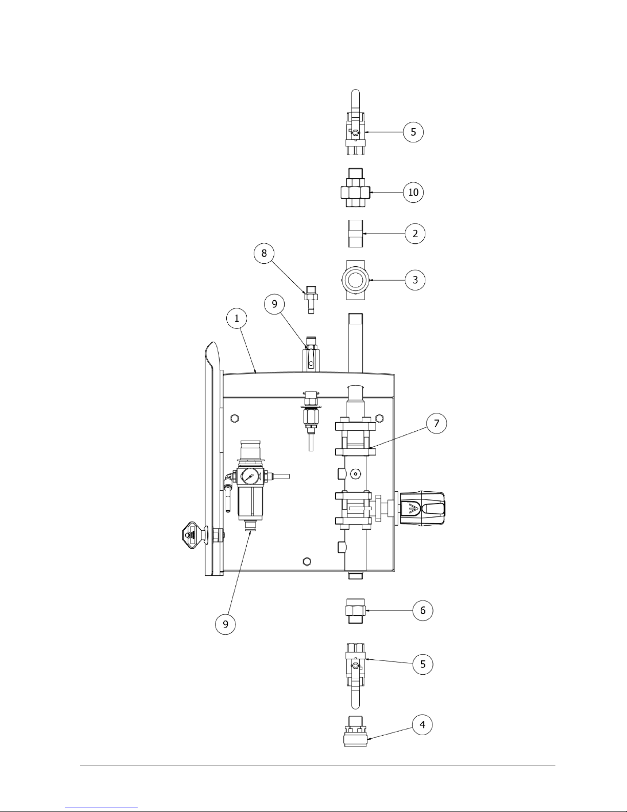
SPARE PARTS

Version 13 (08.2018. EN) (S2)
Page 11 of 48
Pos.
Part no.
Description
Material
Version
1
46-500110
Housing S2
AISI 304
All
2
15-510121
Nipple pipe 1/2"x40mm
AISI 316
3-8 bar
3
20-500061
Strainer 1/2" brass 300 µm
Nickel-plated brass
3-8 bar
4
30-000050
Outlet coupling 1/2"
Special stainless
All
5
20-000220
Ball valve 1/2" (blue)
AISI 316
BSP
5
20-000226
Ball valve 1/2"NPT (blue)
AISI 316
NPT
6
16-800060
Outlet nipple 1/2"x37 E/I
AISI 304
All
7
02-160170
Injector system
-
All
8
15-000010
Adapter ø8x1/4" NPT SS
AISI 304
NPT
9
05-010040
Assembly pneumatic S2
-
All
10
15-800032
Union 1/2" with packing, e/i
AISI 316/PTFE
BSP
10
15-800033
Union 1/2" with packing, NPT
AISI 316/PTFE
NPT

Version 13 (08.2018. EN) (S2)
Page 12 of 48
Cabinet
Pos.
Part no.
Description
Material
1
46-500110
Housing S2
AISI 304
2
72-000011
Lock WITHOUT handle
AISI 304/Plastic
4
72-000030
Nut for lock
Nylon
6
72-100010
Key for housing
Plastic
8
04-000172
Spacer ø8
PVC
11
08-100801
Coach screw M8x60
A2
14
08-900010
Rawlplugs S 10
PVC
Version 13 (08.2018. EN) (S2)
Page 13 of 48
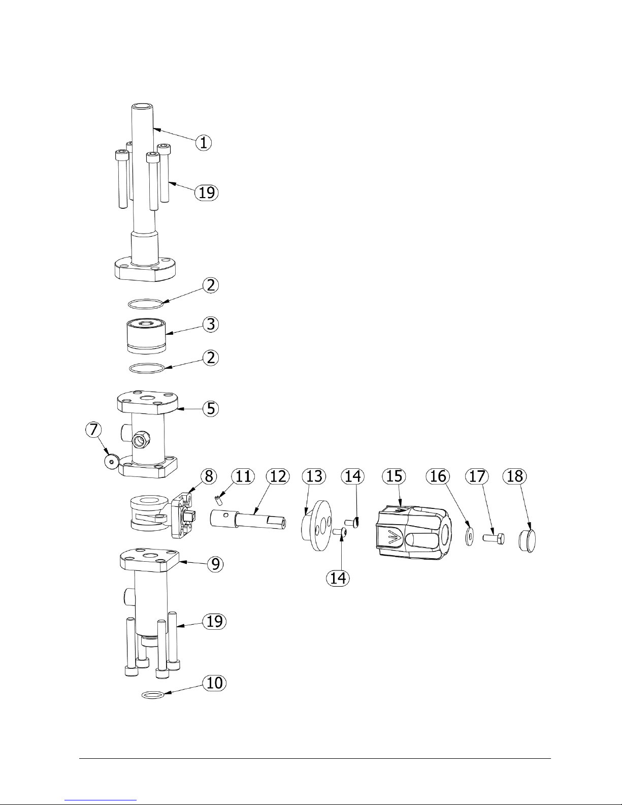
Injector system
Version 13 (08.2018. EN) (S2)
Page 14 of 48
Pos.
Part no.
Description
Material
1
25-000520
Inlet pipe 1/2" BSP
AISI 304
2
17-030129
O-ring 32x1,5 Viton 75 sh
Viton
3
20-200410
Non-return valve 1/2"
AISI 304/NBR
5
25-100420
Intermediate pipe 1/2"
AISI 316
7
16-501802
Plug 1/8"
AISI 316
8
20-000284
Ball valve 1/2" without flange
-
9
25-200350
Outlet pipe 1/2"
AISI 316
10
17-020080
O-ring 18x2 70 shore
EPDM
11
08-105001
Spring pin ø4x14 SS
A2
12
20-000521
Valve stem ø16
AISI 303
13
20-000541
Bushing for valve stem
POM/C
14
08-100501
Screw button head M5x10
A2
15
20-302000
Handle
ABS
16
08-300602
Disc washer ø6
A2
17
08-200606
Set screw M6x16
A2
18
010-200200
Plastic plug ø23xø20mm
Nylon
19
08-800807
Cheese-head screw M8x50
A2
Version 13 (08.2018. EN) (S2)
Page 15 of 48
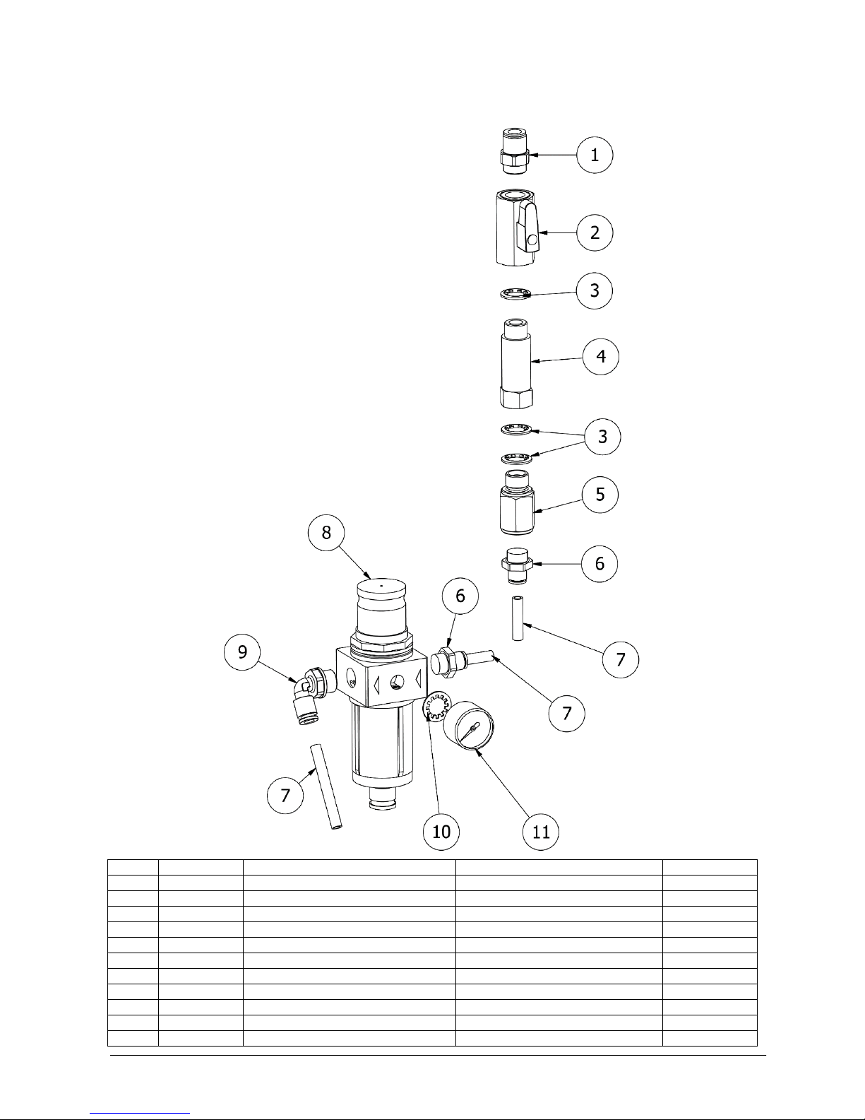
Pneumatic assembly
Pos.
Part no.
Description
Material
Version
1
15-000021
Air fitting 1/4"x8 (inside)
Nickel-plated brass/Plastic
Wall
2
20-000050
Ball valve 1/4"
Nickel-plated brass
All
3
17-000012
Gasket 1/4"
PA12
All
4
16-400010
Extension nipple 1/4"x50
Nickel-plated brass
All
5
20-200020
Non-return valve 1/4" air
AISI 316/NBR
All
6
15-010071
Air fitting 1/4"x6
Nickel-plated brass/Plastic
All
7
55-110040
Air hose ø6mm black
PA12
All
8
20-300042
Regulator with filter without gauge
-
All
9
15-010081
Air fitting 1/4"x6 elbow
Nickel-plated brass/Plastic
All
10
17-000072
Gasket 1/8"
Nylon
All
11
22-000071
Gauge ø20 0-10 bar
AISI 304/brass/glycerine
All

Version 13 (08.2018. EN) (S2)
Page 16 of 48
Function F

Version 13 (08.2018. EN) (S2)
Page 17 of 48
Pos.
Part no.
Description
Material
Version
1
16-110012
Adapter for injector
AISI 316
All
2
17-000132
O-ring 9,92x2,62
NBR
All
3
17-030008
O-ring 7,65x1,78 Viton 70 sh
Viton
All
4
27-200100
Water nozzle ø2,5 mm
AISI 316
3-8 bar
4
27-200020
Water nozzle ø1,8
AISI 316
15-40 bar
5
27-010185
Injector with 2 connections (2 rings)
AISI 316
3-8 bar
5
27-010150
Injector with 2 connections
AISI 316
15-40 bar
13
17-000032
O-ring 10,1x1,6 NBR 70 shore
NBR
All
15
20-400056
Dosing valve concentrated
AISI 316/Viton
All
27
55-200023
Suction hose 1/4"x1500 white
PVC
All
30
27-300040
Suction filter ø6,5
AISI 316
All
32
04-000082
Diaphragm nipple
EPDM
All
34
15-300012
Hose clip for 1/4"
PVC
All
37
04-000232
Cone ø12 black
Plastic
All
40
15-901400
End cap 1/4"
Nickel-plated brass
All
55
15-010161
Air fitting ø2,0
Nickel-plated brass/Plastic
All
56
55-110080
Air hose ø4mm black
PA12
All
57
55-110040
Air hose ø6mm black
PA12
All
58
15-020070
Air fitting 4x6 elbow
Plastic
All

Version 13 (08.2018. EN) (S2)
Page 18 of 48
Option F mix
Version 13 (08.2018. EN) (S2)
Page 19 of 48
Pos.
Part no.
Description
Material
Version
1
16-110012
Adapter for injector
AISI 316
All
2
17-000132
O-ring 9,92x2,62
NBR
All
3
17-030008
O-ring 7,65x1,78 Viton 70 sh
Viton
All
4
27-200100
Water nozzle ø2,5 mm
AISI 316
3-8 bar
4
27-200020
Water nozzle ø1,8
AISI 316
15-40 bar
5
27-010185
Injector with 2 connections (2 rings)
AISI 316
3-8 bar
5
27-010150
Injector with 2 connections
AISI 316
15-40 bar
13
17-000032
O-ring 10,1x1,6 NBR 70 shore
NBR
All
15
20-400056
Dosing valve concentrated
AISI 316/Viton
All
30
27-300040
Suction filter ø6,5
AISI 316
All
32
04-000082
Diaphragm nipple
EPDM
All
34
15-300012
Hose clip for 1/4"
PVC
All
36
55-200051
Suction hose 1/4" red, m
PVC
All
39
55-200041
Suction hose 12x6 blue, m
PVC
All
55
15-010161
Air fitting ø2,0
Nickel-plated brass/Plastic
All
56
55-110080
Air hose ø4mm black
PA12
All
57
55-110040
Air hose ø6mm black
PA12
All
58
15-020070
Air fitting 4x6 elbow
Plastic
All

Version 13 (08.2018. EN) (S2)
Page 20 of 48
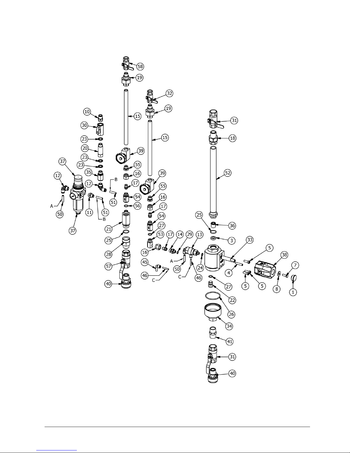
Funktion PF

Version 13 (08.2018. EN) (S2)
Page 21 of 48
Pos.
Part no.
Description
Material
Version
1
010-200200
Plastic plug ø23xø20mm
Nylon
All
2
04-000193
Washer ø18/ø10,4x5
PTFE
All
3
046-000630
Tailstock screw M6x30mm
A2
All
4
08-100026
Allen screw M6x18 CH RFA2
A2
All
5
08-200606
Set screw M6x16
A2
All
6
08-300602
Disc washer ø6
A2
All
7
15-000021
Air fitting 1/4"x8 (inside)
Nickel-plated brass/Plastic
All
8
15-010071
Air fitting 1/4"x6
Nickel-plated brass/Plastic
All
9
15-010081
Air fitting 1/4"x6 elbow
Nickel-plated brass/Plastic
All
10
15-010166
Air fitting elbow ø1,5
Nickel-plated brass/Plastic
All
11
15-100023
Hexagon nipple 1/4"x1/8" SS
AISI 316
All
12
25-050050
Inlet pipe 1/2"x290mm
AISI 316
All
13
15-510225
Nipple pipe 1/4"x225
AISI 316
All
14
15-600020-02
Nut for elbow
AISI 316
All
15
15-600020-03
Nipple with cone 1/8"
AISI 316
All
16
15-800031
Union 1/2"
Nickel-plated brass
BSP
16
15-800033
Union 1/2" with packing, NPT
AISI 316/PTFE
NPT
17
15-800070
Union 1/4" with packing, E/I
AISI 316/PTFE
All
18
16-400010
Extension nipple 1/4"x50
Nickel-plated brass
All
19
16-500009
Plug M16
AISI 316
All
20
17-000012
Gasket 1/4"
PA12
All
21
17-000020
O-ring Ø8x1,25
NBR
All
22
17-020080
O-ring 18x2 70 shore
EPDM
All
23
17-020009
O-ring 48,9x2,62 EPDM 70 sh
EPDM
All
24
17-020055
O-ring 10x2 70 shore
EPDM
All
25
173-000010
O-ring 8x1 EPDM
EPDM
All
26
20-000050
Ball valve 1/4"
Nickel-plated brass
All
27
20-000220
Ball valve 1/2" (blue)
AISI 316
BSP
27
20-000226
Ball valve 1/2"NPT (blue)
AISI 316
NPT
28
20-000242
Ball valve 1/4" SS (white)
AISI 316
BSP
28
20-000244
Ball valve 1/4" SS NPT (white)
AISI 316
NPT
29
20-001001
Valve block PF
-
All
30
20-001100
Outlet valve housing
AISI 303
All
31
20-200020
Non-return valve 1/4" air
AISI 316/NBR
All
32
20-200170
Non-return valve DN 10
Plastic/EPDM
All
33
20-300039
Regulator with filter with gauge
Plastic
All
34
20-302030
Handle
ABS
All
35
20-400012
Needle valve 1/4"
-
All
36
30-000050
Outlet coupling 1/2"
Special stainless
All
37
15-100150
Hexagon nipple 1/2" SS
AISI 316
All
38
55-110040
Air hose ø6mm black
PA12
All
39
55-110080
Air hose ø4mm black
PA12
All
40
15-020070
Air fitting 4x6 elbow
Plastic
All
41
15-600020-04
Housing for Chemical angle
AISI 316
All
42
20-200031
Non-return valve 1/4" chemical (0)
-
All
43
15-200084
Socket 1/4"x1/8"
AISI 316
All
Version 13 (08.2018. EN) (S2)
Page 22 of 48
Funktion PF + PD

Version 13 (08.2018. EN) (S2)
Page 23 of 48
Pos.
Part no.
Description
Material
Version
1
010-200200
Plastic plug ø23xø20mm
Nylon
All
3
04-000193
Washer ø18/ø10,4x5
PTFE
All
4
046-000630
Tailstock screw M6x30mm
A2
All
5
08-100026
Allen screw M6x18 CH RFA2
A2
All
7
08-200606
Set screw M6x16
A2
All
8
08-300602
Disc washer ø6
A2
All
10
15-000021
Air fitting 1/4"x8 (inside)
Nickel-plated brass/Plastic
All
11
15-010071
Air fitting 1/4"x6
Nickel-plated brass/Plastic
All
12
15-010081
Air fitting 1/4"x6 elbow
Nickel-plated brass/Plastic
All
13
15-010166
Air fitting elbow ø1,5
Nickel-plated brass/Plastic
All
14
15-100023
Hexagon nipple 1/4"x1/8" SS
AISI 316
All
15
15-510225
Nipple pipe 1/4"x225
AISI 316
All
16
15-600020-02
Nut for elbow
AISI 316
All
17
15-600020-03
Nipple with cone 1/8"
AISI 316
All
18
15-800031
Union 1/2"
Nickel-plated brass
BSP
18
15-800033
Union 1/2" with packing, NPT
AISI 316/PTFE
NPT
19
15-800070
Union 1/4" with packing, E/I
AISI 316/PTFE
All
20
16-400010
Extension nipple 1/4"x50
Nickel-plated brass
All
21
16-400090
Extension nipple 1/4"x1/2"
AISI 316
All
22
16-500009
Plug M16
AISI 316
All
23
17-000012
Gasket 1/4"
PA12
All
24
17-000020
O-ring Ø8x1,25
NBR
All
25
17-020080
O-ring 18x2 70 shore
EPDM
All
26
17-020009
O-ring 48,9x2,62 EPDM 70 sh
EPDM
All
27
17-020055
O-ring 10x2 70 shore
EPDM
All
28
16-800060
Outlet nipple 1/2"x37 E/I
AISI 304
All
29
173-000010
O-ring 8x1 EPDM
EPDM
All
30
20-000050
Ball valve 1/4"
Nickel-plated brass
All
31
20-000220
Ball valve 1/2" (blue)
AISI 316
BSP
31
20-000226
Ball valve 1/2"NPT (blue)
AISI 316
NPT
32
20-000242
Ball valve 1/4" SS (white)
AISI 316
BSP
32
20-000244
Ball valve 1/4" SS NPT (white)
AISI 316
NPT
33
20-001001
Valve block PF
-
All
34
20-001100
Outlet valve housing
AISI 303
All
35
20-200020
Non-return valve 1/4" air
AISI 316/NBR
All
36
20-200170
Non-return valve DN 10
Plastic/EPDM
All
37
20-300039
Regulator with filter with gauge
Plastic
All
38
20-302030
Handle
ABS
All
39
20-400012
Needle valve 1/4"
-
All
40
30-000050
Outlet coupling 1/2"
Special stainless
All
41
15-100150
Hexagon nipple 1/2" SS
AISI 316
All
45
15-020070
Air fitting 4x6 elbow
Plastic
All
46
55-110080
Air hose ø4mm black
PA12
All
50
55-110040
Air hose ø6mm black
PA12
All
51
55-110040
Air hose ø6mm black
PA12
All
52
25-050050
Inlet pipe 1/2"x290mm
AISI 316
All
53
15-600020-04
Housing for Chemical angle
AISI 316
All
54
20-200031
Non-return valve 1/4" chemical (0)
-
All
55
15-200084
Socket 1/4"x1/8"
AISI 316
All
56
17-020056
O-ring 11x1,5 70 shore
EPDM
All
57
20-000221
Ball valve 1/2" (Yellow)
AISI 316
All
58
20-000241
Ball valve 1/4" SS (Yellow)
AISI 316
BSP
58
20-000245
Ball valve 1/4" SS NPT (Yellow)
AISI 316
NPT

Version 13 (08.2018. EN) (S2)
Page 24 of 48
Funktion PF + PF

Version 13 (08.2018. EN) (S2)
Page 25 of 48
Pos.
Part no.
Description
Material
Version
1
010-200200
Plastic plug ø23xø20mm
Nylon
All
3
04-000193
Washer ø18/ø10,4x5
PTFE
All
4
046-000630
Tailstock screw M6x30mm
A2
All
5
08-100026
Allen screw M6x18 CH RFA2
A2
All
7
08-200606
Set screw M6x16
A2
All
8
08-300602
Disc washer ø6
A2
All
10
15-000021
Air fitting 1/4"x8 (inside)
Nickel-plated brass/Plastic
All
11
15-010071
Air fitting 1/4"x6
Nickel-plated brass/Plastic
All
12
15-010081
Air fitting 1/4"x6 elbow
Nickel-plated brass/Plastic
All
13
15-010111
Air fitting 6/6/6 (T-piece)
Plastic
All
14
15-010120
Air fitting 6x6 elbow
Plastic
All
15
15-010166
Air fitting elbow ø1,5
Nickel-plated brass/Plastic
All
16
15-010041
Air fiting 6/4/4 Y
Plastic
All
17
15-100023
Hexagon nipple 1/4"x1/8" SS
AISI 316
All
18
15-100150
Hexagon nipple 1/2" SS
AISI 316
All
19
15-200084
Socket 1/4"x1/8"
AISI 316
All
20
15-510225
Nipple pipe 1/4"x225
AISI 316
All
21
15-600020-02
Nut for elbow
AISI 316
All
22
15-600020-03
Nipple with cone 1/8"
AISI 316
All
23
15-600020-04
Housing for Chemical angle
AISI 316
All
24
15-800031
Union 1/2"
Nickel-plated brass
BSP
24
15-800033
Union 1/2" with packing, NPT
AISI 316/PTFE
NPT
25
15-800070
Union 1/4" with packing, E/I
AISI 316/PTFE
All
26
16-400010
Extension nipple 1/4"x50
Nickel-plated brass
All
27
16-400095
Extension nipple 1/4"x1/2"
AISI 304
All
28
16-500009
Plug M16
AISI 316
All
29
16-800060
Outlet nipple 1/2"x37 E/I
AISI 304
All
30
17-000012
Gasket 1/4"
PA12
All
31
17-000020
O-ring Ø8x1,25
NBR
All
32
17-020009
O-ring 48,9x2,62 EPDM 70 sh
EPDM
All
33
17-020055
O-ring 10x2 70 shore
EPDM
All
34
17-020056
O-ring 11x1,5 70 shore
EPDM
All
35
17-020080
O-ring 18x2 70 shore
EPDM
All
36
173-000010
O-ring 8x1 EPDM
EPDM
All
37
20-000050
Ball valve 1/4"
Nickel-plated brass
All
38
20-000220
Ball valve 1/2" (blue)
AISI 316
BSP
38
20-000226
Ball valve 1/2"NPT (blue)
AISI 316
NPT
39
20-000242
Ball valve 1/4" SS (white)
AISI 316
BSP
39
20-000244
Ball valve 1/4" SS NPT (white)
AISI 316
NPT
40
20-001001
Valve block PF
-
All
41
20-001100
Outlet valve housing
AISI 303
All
42
20-200020
Non-return valve 1/4" air
AISI 316/NBR
All
43
20-200031
Non-return valve 1/4" chemical (0)
-
All
44
20-200170
Non-return valve DN 10
Plastic/EPDM
All
45
20-300039
Regulator with filter with gauge
Plastic
All
46
20-302030
Handle
ABS
All
47
20-400012
Needle valve 1/4"
-
All
48
25-050050
Inlet pipe 1/2"x290mm
AISI 316
All
49
30-000050
Outlet coupling 1/2"
Special stainless
All
53
55-110040
Air hose ø6mm black
PA12
All
54
55-110080
Air hose ø4mm black
PA12
All
Version 13 (08.2018. EN) (S2)
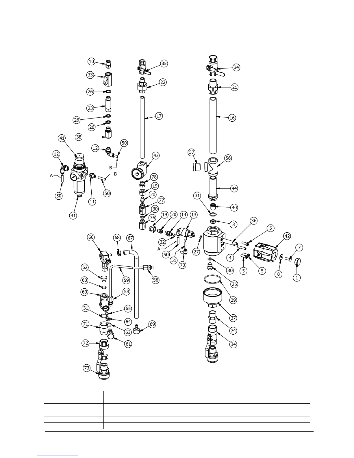
Page 26 of 48
Funktion PF + D
Pos.
Part no.
Description
Material
Version
1
010-200200
Plastic plug ø23xø20mm
Nylon
All
3
04-000193
Washer ø18/ø10,4x5
PTFE
All
4
046-000630
Tailstock screw M6x30mm
A2
All
5
08-100026
Allen screw M6x18 CH RFA2
A2
All
7
08-200606
Set screw M6x16
A2
All

Version 13 (08.2018. EN) (S2)
Page 27 of 48
8
08-300602
Disc washer ø6
A2
All
10
15-000021
Air fitting 1/4"x8 (inside)
Nickel-plated brass/Plastic
All
11
15-010071
Air fitting 1/4"x6
Nickel-plated brass/Plastic
All
12
15-010081
Air fitting 1/4"x6 elbow
Nickel-plated brass/Plastic
All
13
15-010166
Air fitting elbow ø1,5
Nickel-plated brass/Plastic
All
14
15-100023
Hexagon nipple 1/4"x1/8" SS
AISI 316
All
16
15-510230
Nipple pipe 1/2"x200mm
AISI 316
All
17
15-510225
Nipple pipe 1/4"x225
AISI 316
All
19
15-600020-02
Nut for elbow
AISI 316
All
20
15-600020-03
Nipple with cone 1/8"
AISI 316
All
21
15-800031
Union 1/2"
Nickel-plated brass
BSP
21
15-800033
Union 1/2" with packing, NPT
AISI 316/PTFE
NPT
22
15-800070
Union 1/4" with packing, E/I
AISI 316/PTFE
All
23
16-400010
Extension nipple 1/4"x50
Nickel-plated brass
All
25
16-500009
Plug M16
AISI 316
All
26
17-000012
Gasket 1/4"
PA12
All
27
17-000020
O-ring Ø8x1,25
NBR
All
29
17-020009
O-ring 48,9x2,62 EPDM 70 sh
EPDM
All
30
17-020055
O-ring 10x2 70 shore
EPDM
All
31
17-020080
O-ring 18x2 70 shore
EPDM
All
32
173-000010
O-ring 8x1 EPDM
EPDM
All
33
20-000050
Ball valve 1/4"
Nickel-plated brass
All
34
20-000220
Ball valve 1/2" (blue)
AISI 316
BSP
34
20-000226
Ball valve 1/2"NPT (blue)
AISI 316
NPT
35
20-000242
Ball valve 1/4" SS (white)
AISI 316
BSP
35
20-000244
Ball valve 1/4" SS NPT (white)
AISI 316
NPT
36
20-001001
Valve block PF
-
All
37
20-001100
Outlet valve housing
AISI 303
All
38
20-200020
Non-return valve 1/4" air
AISI 316/NBR
All
40
20-200170
Non-return valve DN 10
Plastic/EPDM
All
41
20-300039
Regulator with filter with gauge
Plastic
All
42
20-302030
Handle
ABS
All
43
20-400012
Needle valve 1/4"
-
All
44
25-000720
Inlet pipe 1/2" BSP
AISI 304
All
50
55-110040
Air hose ø6mm black
PA12
All
51
55-110080
Air hose ø4mm black
PA12
All
56
15-700030
Tee, 1/4" I/I/I
AISI 316
All
57
15-200130
Socket 1/2"x1/8"
AISI 316
All
58
26-100020
Clamping ring fitting 1/8"x6
AISI 316
All
59
26-000431
Pipe ø6x1 for injector
AISI 316
All
60
27-010111
Injector housing with 1 connection
AISI 316
All
61
16-100100
Adapter 1/8"xM12x1
AISI 316
All
62
16-500010
Plug M12x1
AISI 316
All
63
17-000132
O-ring 9,92x2,62
NBR
All
64
27-200020
Water nozzle ø1,8
AISI 316
All
65
17-030008
O-ring 7,65x1,78 Viton 70 sh
Viton
All
66
20-400056
Dosing valve concentrated
AISI 316/Viton
All
67
55-200060
Suction hose 1/4"x1650 yellow
PVC
All
68
15-300012
Hose clip for 1/4"
PVC
All
69
27-300040
Suction filter ø6,5
AISI 316
All
70
15-020070
Air fitting 4x6 elbow
Plastic
All
71
16-800060
Outlet nipple 1/2"x37 E/I
AISI 304
All
72
20-000221
Ball valve 1/2" (Yellow)
AISI 316
All
73
30-000050
Outlet coupling 1/2"
Special stainless
All
74
15-100150
Hexagon nipple 1/2" SS
AISI 316
All
76
15-600020-04
Housing for Chemical angle
AISI 316
All
77
20-200031
Non-return valve 1/4" chemical (0)
-
All
78
15-200084
Socket 1/4"x1/8"
AISI 316
All

Version 13 (08.2018. EN) (S2)
Page 28 of 48
Funktion PF + F
Pos.
Part no.
Description
Material
Version
10
15-000021
Air fitting 1/4"x8 (inside)
Nickel-plated brass/Plastic
All
11
20-000050
Ball valve 1/4"
Nickel-plated brass
All
12
17-000012
Gasket 1/4"
PA12
All
13
16-400010
Extension nipple 1/4"x50
Nickel-plated brass
All
14
20-200020
Non-return valve 1/4" air
AISI 316/NBR
All
15
15-010081
Air fitting 1/4"x6 elbow
Nickel-plated brass/Plastic
All
16
55-110040
Air hose ø6mm black
PA12
All

Version 13 (08.2018. EN) (S2)
Page 29 of 48
17
15-010111
Air fitting 6/6/6 (T-piece)
Plastic
All
18
15-010120
Air fitting 6x6 elbow
Plastic
All
19
15-010041
Air fiting 6/4/4 Y
Plastic
All
20
55-110080
Air hose ø4mm black
PA12
All
21
04-000082
Diaphragm nipple
EPDM
All
22
55-200020
Suction hose 1/4" white, m
PVC
All
23
27-300040
Suction filter ø6,5
AISI 316
All
24
15-010162
Air fitting elbow ø2,0
Nickel-plated brass/Plastic
All
25
17-000032
O-ring 10,1x1,6 NBR 70 shore
NBR
All
26
20-400056
Dosing valve concentrated
AISI 316/Viton
All
27
15-300012
Hose clip for 1/4"
PVC
All
28
27-010111
Injector housing with 1 connection
AISI 316
All
29
17-030008
O-ring 7,65x1,78 Viton 70 sh
Viton
All
30
27-200020
Water nozzle ø1,8
AISI 316
All
31
17-000132
O-ring 9,92x2,62
NBR
All
32
16-100100
Adapter 1/8"xM12x1
AISI 316
All
33
26-100020
Clamping ring fitting 1/8"x6
AISI 316
All
34
26-000432
Pipe ø6x1 for injector
AISI 316
All
35
17-020080
O-ring 18x2 70 shore
EPDM
All
36
16-800060
Outlet nipple 1/2"x37 E/I
AISI 304
All
37
20-000220
Ball valve 1/2" (blue)
AISI 316
BSP
37
20-000226
Ball valve 1/2"NPT (blue)
AISI 316
NPT
38
30-000050
Outlet coupling 1/2"
Special stainless
All
39
20-000242
Ball valve 1/4" SS (white)
AISI 316
BSP
39
20-000244
Ball valve 1/4" SS NPT (white)
AISI 316
NPT
40
15-800070
Union 1/4" with packing, E/I
AISI 316/PTFE
All
41
15-510225
Nipple pipe 1/4"x225
AISI 316
All
42
20-400012
Needle valve 1/4"
-
All
45
15-600020-02
Nut for elbow
AISI 316
All
46
15-600020-03
Nipple with cone 1/8"
AISI 316
All
47
15-100023
Hexagon nipple 1/4"x1/8" SS
AISI 316
All
48
173-000010
O-ring 8x1 EPDM
EPDM
All
49
15-010166
Air fitting elbow ø1,5
Nickel-plated brass/Plastic
All
50
17-000020
O-ring Ø8x1,25
NBR
All
51
15-800031
Union 1/2"
Nickel-plated brass
BSP
51
15-800033
Union 1/2" with packing, NPT
AISI 316/PTFE
NPT
52
15-510230
Nipple pipe 1/2"x200mm
AISI 316
All
53
26-100050
Clamping ring fitting 1/4"x6
AISI 316
All
54
15-200070
Socket 1/2"x1/4"
AISI 316
All
55
15-700030
Tee, 1/4" I/I/I
AISI 316
All
56
25-000720
Inlet pipe 1/2" BSP
AISI 304
All
57
20-200170
Non-return valve DN 10
Plastic/EPDM
All
58
04-000193
Washer ø18/ø10,4x5
PTFE
All
59
20-001001
Valve block PF
-
All
60
046-000630
Tailstock screw M6x30mm
A2
All
61
08-100026
Allen screw M6x18 CH RFA2
A2
All
62
20-302030
Handle
ABS
All
63
08-300602
Disc washer ø6
A2
All
64
08-200606
Set screw M6x16
A2
All
65
010-200200
Plastic plug ø23xø20mm
Nylon
All
66
17-020055
O-ring 10x2 70 shore
EPDM
All
67
16-500009
Plug M16
AISI 316
All
68
17-020009
O-ring 48,9x2,62 EPDM 70 sh
EPDM
All
69
20-001100
Outlet valve housing
AISI 303
All
70
15-100150
Hexagon nipple 1/2" SS
AISI 316
All
71
15-010071
Air fitting 1/4"x6
Nickel-plated brass/Plastic
All
72
20-300039
Regulator with filter with gauge
Plastic
All
87
15-600020-04
Housing for Chemical angle
AISI 316
All
88
20-200031
Non-return valve 1/4" chemical (0)
-
All
89
15-200084
Socket 1/4"x1/8"
AISI 316
All
Version 13 (08.2018. EN) (S2)
Page 30 of 48
Separate F-injector

Version 13 (08.2018. EN) (S2)
Page 31 of 48
Pos.
Part no.
Description
Material
Version
1
27-010111
Injector housing with 1 connection
AISI 316
15-40 bar
1
27-010180-01
Injector with 1 connections
AISI 316
3-8 bar
2
20-000220
Ball valve 1/2" (blue)
AISI 316
All
3
16-800060
Outlet nipple 1/2"x37 E/I
AISI 304
All
4
30-000050
Outlet coupling 1/2"
Special stainless
All
5
17-020080
O-ring 18x2 70 sh
EPDM
All
6
26-100020
Clamping ring fitting 1/8"x6
AISI 316
All
7
16-100100
Adapter 1/8"xM12x1
AISI 316
All
8
17-000132
O-ring 9,92x2,62
NBR
All
9
27-200100
Water nozzle ø2,5 mm
AISI 316
3-8 bar
9
27-200020
Water nozzle ø1,8
AISI 316
15-40 bar
10
17-030008
O-ring 7,65x1,78 Viton 70 sh
Viton
All
12
17-000032
O-ring 10,1x1,6 NBR 70 shore
NBR
All
13
26-100030
Clamping ring fitting 1/8"x6
AISI 316
All
14
26-000430
Pipe ø6x1 for injector
AISI 316
All
18
20-400056
Dosing valve concentrated
AISI 316/Viton
All
19
27-300040
Suction filter ø6,5
AISI 316
All
20
55-200010
Suction hose 1/4"x1650 white
PVC
All
21
04-000082
Diaphragm nipple
EPDM
All
22
15-300012
Hose clip for 1/4"
PVC
All
28
15-600350
Elbow 1/2" SS 45° E/I
AISI 316
Trolley
29
15-010162
Air fitting elbow ø2,0
Nickel-plated brass/Plastic
All
30
55-110080
Air hose ø4mm black
PA12
All
31
15-010041
Air fiting 6/4/4 Y
Plastic
All
33
15-010120
Air fitting 6x6 elbow
Plastic
All
34
55-110045
Air hose ø6x200 black
PA12
All
35
15-010040
Air fitting ø6 Y
Plastic
All
36
55-110036
Air hose 6x40 black
PA12
All

Version 13 (08.2018. EN) (S2)
Page 32 of 48
Separate D-injector

Version 13 (08.2018. EN) (S2)
Page 33 of 48
Pos.
Part no.
Description
Material
Version
1
27-010111
Injector housing with 1 connection
AISI 316
15-40 bar
1
27-010180-01
Injector with 1 connections
AISI 316
3-8 bar
2
17-000132
O-ring 9,92x2,62
NBR
All
3
16-500010
Plug M12x1
AISI 316
All
4
16-100100
Adapter 1/8"xM12x1
AISI 316
All
5
26-100020
Clamping ring fitting 1/8"x6
AISI 316
All
6
17-030008
O-ring 7,65x1,78 Viton 70 sh
Viton
All
7
17-000132
O-ring 9,92x2,62
NBR
All
8
27-200020
Water nozzle ø1,8
AISI 316
15-40 bar
8
27-200100
Water nozzle ø2,5 mm
AISI 316
3-8 bar
9
26-000430
Pipe ø6x1 for injector
AISI 316
All
10
16-800060
Outlet nipple 1/2"x37 E/I
AISI 304
All
11
30-000050
Outlet coupling 1/2"
Special stainless
All
12
20-000221
Ball valve 1/2" (Yellow)
AISI 316
All
13
17-020080
O-ring 18x2 70 shore
EPDM
All
14
15-600350
Elbow 1/2" SS 45° E/I
AISI 316
Trolley
15
26-100030
Clamping ring fitting 1/8"x6
AISI 316
All
16
15-300012
Hose clip for 1/4"
PVC
All
17
04-000082
Diaphragm nipple
EPDM
All
18
55-200060
Suction hose 1/4"x1650 yellow
PVC
All
19
27-300040
Suction filter ø6,5
AISI 316
All
20
20-400056
Dosing valve concentrated
AISI 316/Viton
All

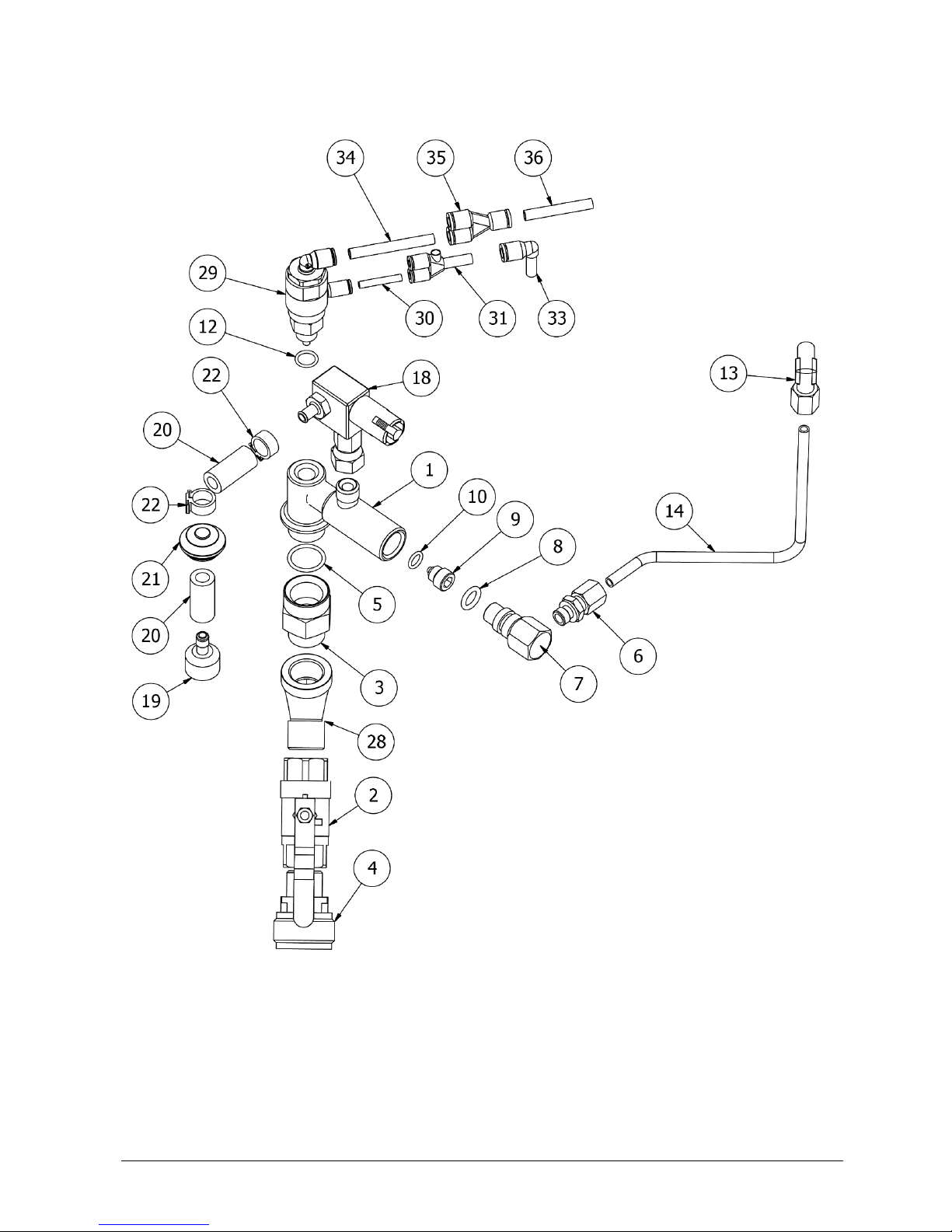
Version 13 (08.2018. EN) (S2)
Page 34 of 48
Fixed dosing

Version 13 (08.2018. EN) (S2)
Page 35 of 48
Pos.
Part no.
Description
Material
1
20-200111
Non-return valve for dosing valve VITON
Viton/AISI 316
2
182-000180-01
Hose nipple 1/8"
AISI 316
3
27-300040
Suction filter ø6,5
AISI 316
4
04-000082
Diaphragm nipple
EPDM
5
15-300012
Hose clip for 1/4"
PVC
6
55-200010
Suction hose 1/4"x1650 white
PVC
6
55-200040
Suction hose 1/4"x1650 blue
PVC
6
55-200052
Suction hose 1/4"x1650 red
PVC
6
55-200060
Suction hose 1/4"x1650 yellow
PVC
7
15-600341
Elbow 1/8" 90°, i/i
AISI 316
8
294-100000
Set of chemical limiter (7)
PVC
9
17-000072
Gasket 1/8"
Nylon

Version 13 (08.2018. EN) (S2)
Page 36 of 48
Fixed dosing stainless
Pos.
Part no.
Description
Material
1
55-600010
Hose nipple 1/4"x7,5
AISI 316
2
17-000012
Gasket 1/4"
PA12
3
17-000122
O-ring 6,0x1,5 Viton
Viton
4
27-400004-01
Chemical limiter ø0,4 SS
AISI 316
4
27-400005-01
Chemical limiter ø0,5 SS
AISI 316
4
27-400006-01
Chemical limiter ø0,6 SS
AISI 316
4
27-400007-01
Chemical limiter ø0,7 SS
AISI 316
4
27-400008-01
Chemical limiter ø0,8 SS
AISI 316
4
27-400009-01
Chemical limiter ø0,9 SS
AISI 316
4
27-400010-01
Chemical limiter ø1,0 SS
AISI 316
4
27-400012-01
Chemical limiter ø1,2 SS
AISI 316
4
27-400014-01
Chemical limiter ø1,4 SS
AISI 316
4
27-400016-01
Chemical limiter ø1,6 SS
AISI 316
5
20-200111
Non-return valve for dosing valve VITON
Viton/AISI 316
6
15-600030-01
Housing for Chemical angle
AISI 316

Version 13 (08.2018. EN) (S2)
Page 37 of 48
Dosing valve
Foam (White / Blue / Red)
Pos.
Part no.
Description
Material
1
27-300040
Suction filter ø6,5
AISI 316
2
04-000082
Diaphragm nipple
EPDM
3
15-300012
Hose clip for 1/4"
PVC
4
20-400056
Dosing valve concentrated
AISI 316/Viton
5
55-200010
Suction hose 1/4"x1650 white
PVC
5
55-200040
Suction hose 1/4"x1650 blue
PVC
5
55-200052
Suction hose 1/4"x1650 red
PVC
Disinfection (Yellow)
Pos.
Part no.
Description
Material
1
27-300040
Suction filter ø6,5
AISI 316
2
04-000082
Diaphragm nipple
EPDM
3
15-300012
Hose clip for 1/4"
PVC
4
20-400056
Dosing valve concentrated
AISI 316/Viton
5
55-200060
Suction hose 1/4"x1650 yellow
PVC

Version 13 (08.2018. EN) (S2)
Page 38 of 48
Base - Trolley

Version 13 (08.2018. EN) (S2)
Page 39 of 48
Pos.
Part no.
Description
Material
Version
1
46-500110
Housing S2
AISI 304
All
7
30-000050
Outlet coupling 1/2"
Special stainless
All
9
20-000220
Ball valve 1/2" (blue)
AISI 316
All
10
02-160170
Injector system
-
All
12
16-800060
Outlet nipple 1/2"x37 E/I
AISI 304
All
17
30-400040
Air nipple, 1/4" external thread
Chrome-plated brass
All
18
15-600350
Elbow 1/2" SS 45° E/I
AISI 316
All
19
05-010040
Assembly pneumatic S2
-
All
20
30-000010
Outlet coupling 1/2", internal
AISI 303
All
22
30-000070
Insert 1/2" external thread
16-2-XH
All
23
20-500060
Strainer 1/2" brass 300 µm
Nickel-plated brass
3-8 bar
24
17-000252
Packing for low pressure valve
-
3-8 bar
25
15-600070
Elbow 1/2" 90° I/I
AISI 316
All
28
15-600061
Elbow 1/4" 90° E/I
Nickel-plated brass
All
42
48-100077
Trolley - All
43
17-000012
Gasket 1/4"
PA12
All
Version 13 (08.2018. EN) (S2)
Page 40 of 48
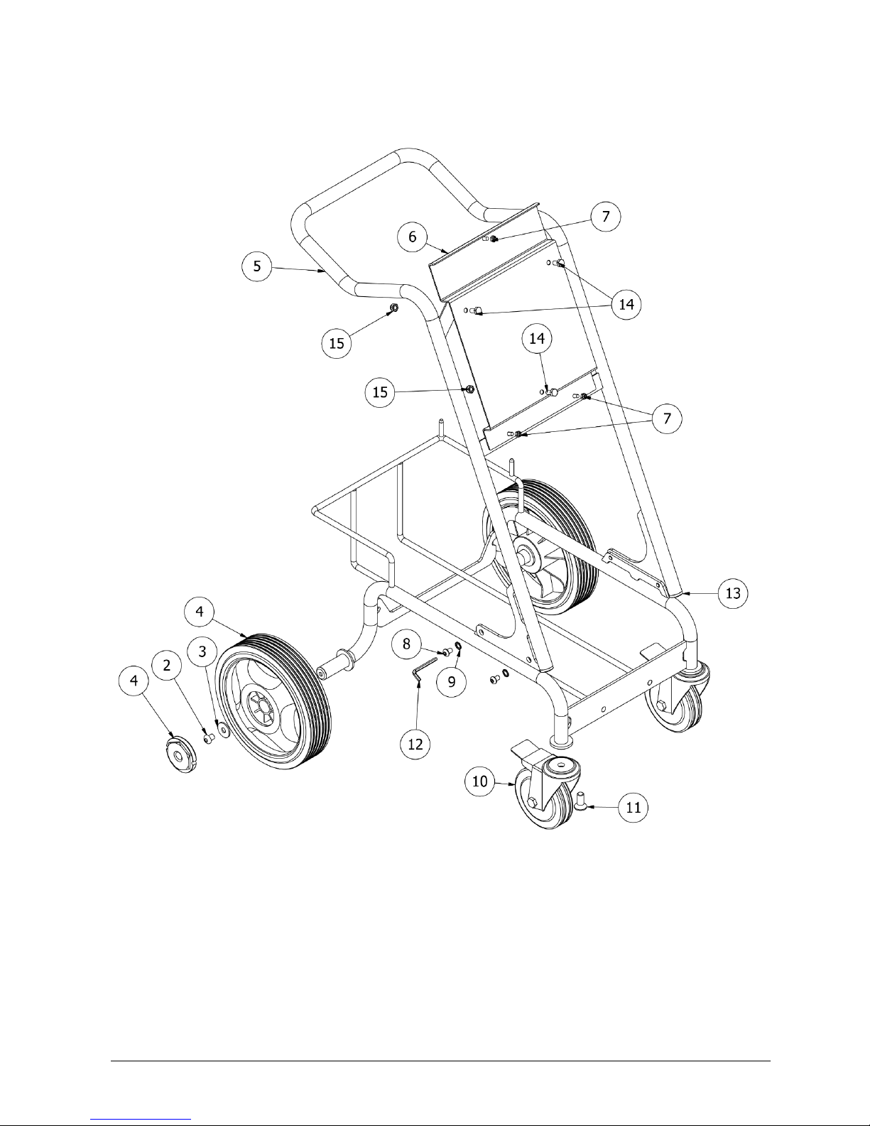
Trolley

Version 13 (08.2018. EN) (S2)
Page 41 of 48
Pos.
Part no.
Description
Material
2
08-101001
Screw button head M10x12
A2
3
08-301002
Disc washer ø10
A2
4
49-000022
Wheel ø250x60mm
Rubber/Plastic
5
700-100020-01
Trolley
AISI 304
6
48-130040
Mounting bracket for satellite
AISI 304
7
08-000602
Lock nut M6
A2
8
08-100003
Allen screw M8x12
A2
9
08-300804
Toothed disk ø8
A2
10
49-100012
Wheel with lock ø125mm
Rubber/Plastic/AISI 304
11
08-800850
Screw M12x30 countersunk head (hexagon)
A2
12
97-100340
Allen key 5mm
Steel
13
04-000092
Plastic knob ø25mm
White PP
14
08-200808
Set screw M8x16
A2
15
08-000805
Lock nut M8
A2
Version 13 (08.2018. EN) (S2)
Page 42 of 48
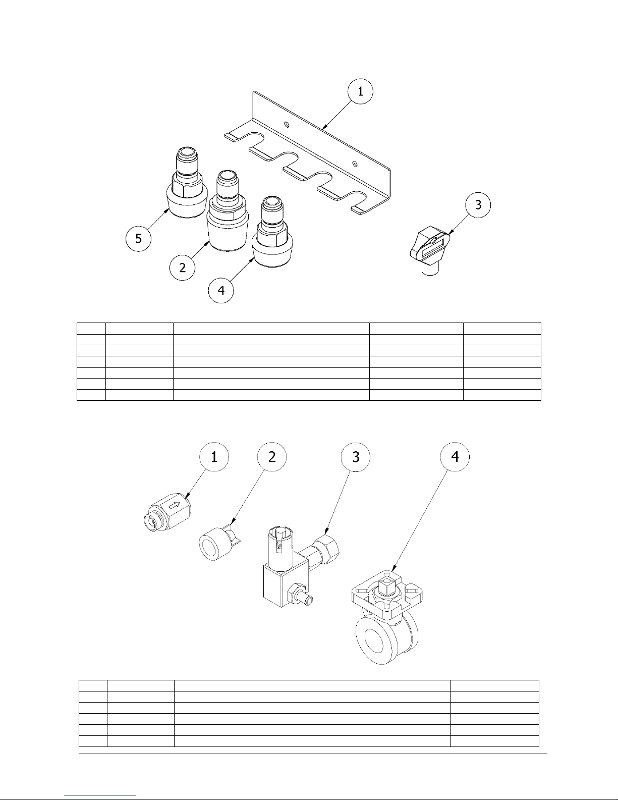
Accessories
Pos.
Part no.
Description
Material
Version
1
57-000050-01
Nozzle holder for 4 System nozzles
AISI 304
All
2
53-502000
Foam nozzle System 50/200 BR
-
All
3
72-100010
Key for housing
Plastic
All
4
52-160300
Disinfection nozzle 60/30 KS
-
All
5
53-010401
Rinse nozzle System 10/40 BR
-
3-8 bar
5
53-015301
Rinse nozzle System 15/30 BR
-
15-40 bar
RECOMMENDED SPARE PARTS
Pos.
Part no.
Description
Material
1
20-200020
Non-return valve 1/4" air
AISI 316/NBR
1
20-200021
Non-return valve 1/4" chemical (0)
-
2
20-200175
Non-return valve DN 20
PPO-GF/EPDM
3
20-400056
Dosing valve concentrated
AISI 316/Viton
4
20-000284
Ball valve 1/2" without flange
-

Version 13 (08.2018. EN) (S2)
Page 43 of 48
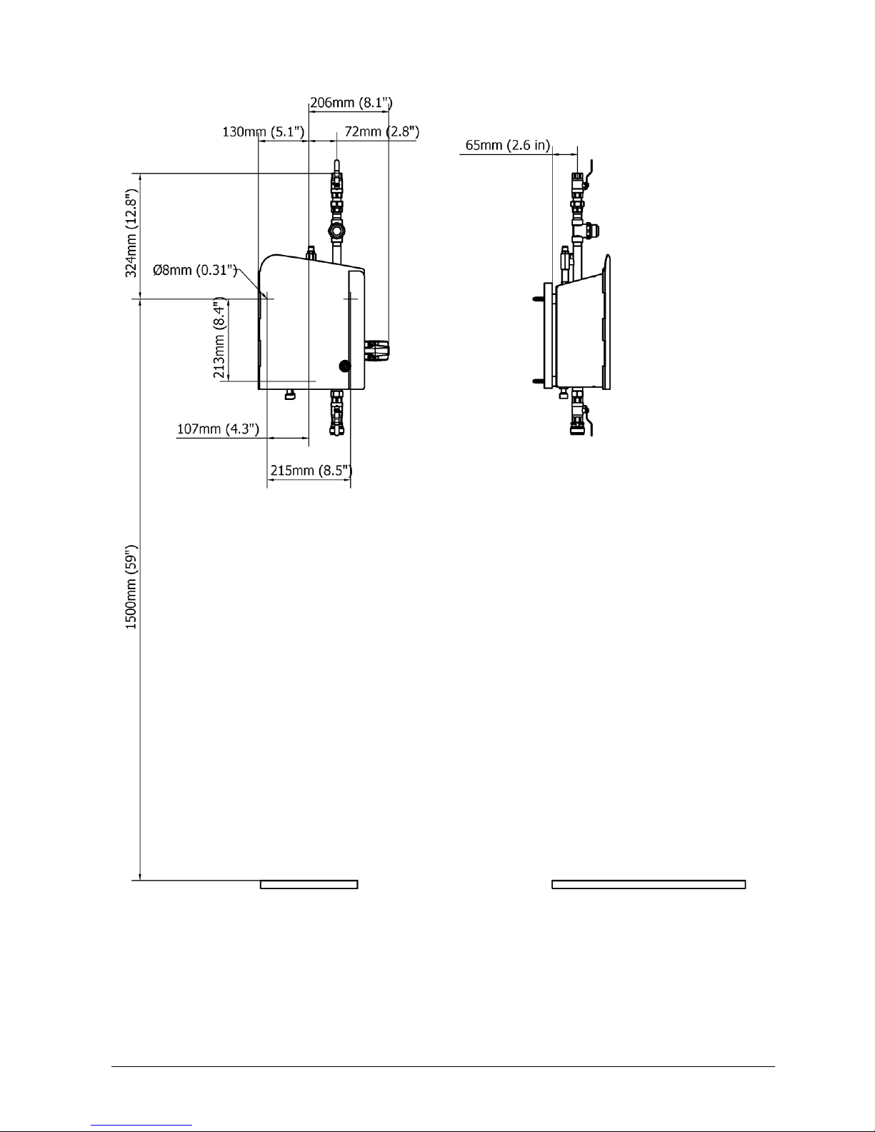
TECHNICAL SPECIFICATIONS WALL

Version 13 (08.2018. EN) (S2)
Page 44 of 48
TECHNICAL SPECIFICATIONS WALL S2 PF + PF
Version 13 (08.2018. EN) (S2)
Page 45 of 48
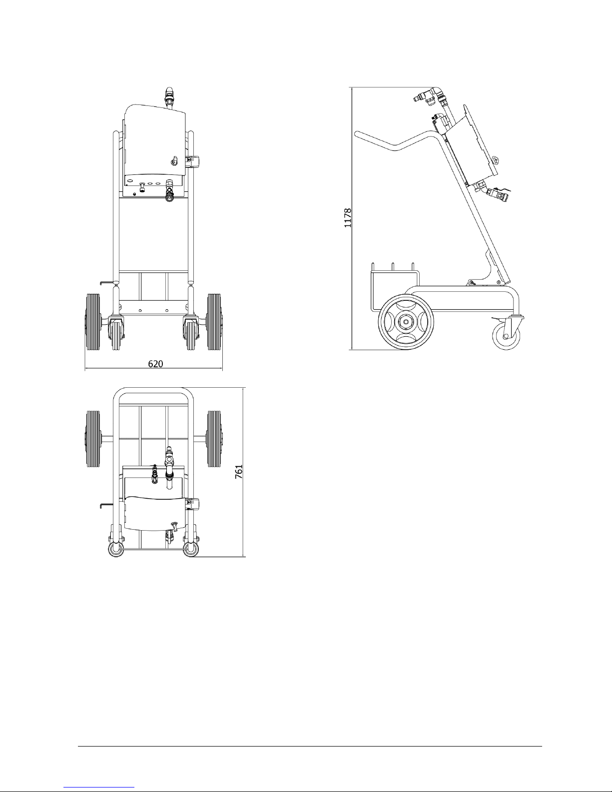
TECHNICAL SPECIFICATIONS TROLLEY
Version 13 (08.2018. EN) (S2)
Page 46 of 48
TECHNICAL SPECIFICATIONS WALL
Model
S2
S2
Installation
Ambient temperature
3-40°C / 37-104°F
Connections
Air inlet
Ø8
1/4" NPT
Water inlet
1/2" BSP
1/2" NPT
Outlet
SC coupling
Water
Maximum pressure
40 bar / 580 psi
Temperature
3-70°C / 37-160°F
Minimum recommended flow
30 liter/min / 7.9 USgal/min
Air
Pressure
5-10 bar / 72-145 psi
Minimum flow
150 liter/min / 5.3 cfm
Chemical
Max. pressure pre-diluted
12 bar / 174 psi
Dosing range
0.2–6%*
Outlet hose
Water pressure 3-8 bar / 44-116 psi
3/4", 10-15 m / 33-49 ft
Water pressure 15-40 bar / 44-580 psi
1/2", 10-35 m / 33-115 ft
Dimensions
Weight
10 kg / 22 lbs

Version 13 (08.2018. EN) (S2)
Page 47 of 48
TECHNICAL SPECIFICATIONS TROLLEY
Model
S2
S2
Installation
Ambient temperature
3-40°C / 37-104°F
Connections
Air inlet
Ø8
1/4" NPT
Water inlet
1/2" Insert
1/2" Insert
Outlet
SC coupling
Water
Maximum pressure
40 bar / 580 psi
Temperature
3-70°C / 37-160°F
Minimum recommended flow
30 liter/min / 7.9 USgal/min
Air
Pressure
5-10 bar / 72-145 psi
Minimum flow
150 liter/min / 5.3 cfm
Chemical
Max. pressure pre-diluted
12 bar / 174 psi
Dosing range
0.2–6%*
Outlet hose
Water pressure 3-8 bar / 44-116 psi
3/4", 10-15 m / 33-49 ft
Water pressure 15-40 bar / 44-580 psi
1/2", 10-35 m / 33-115 ft
Dimensions
Weight
30,5 kg / 67 lbs
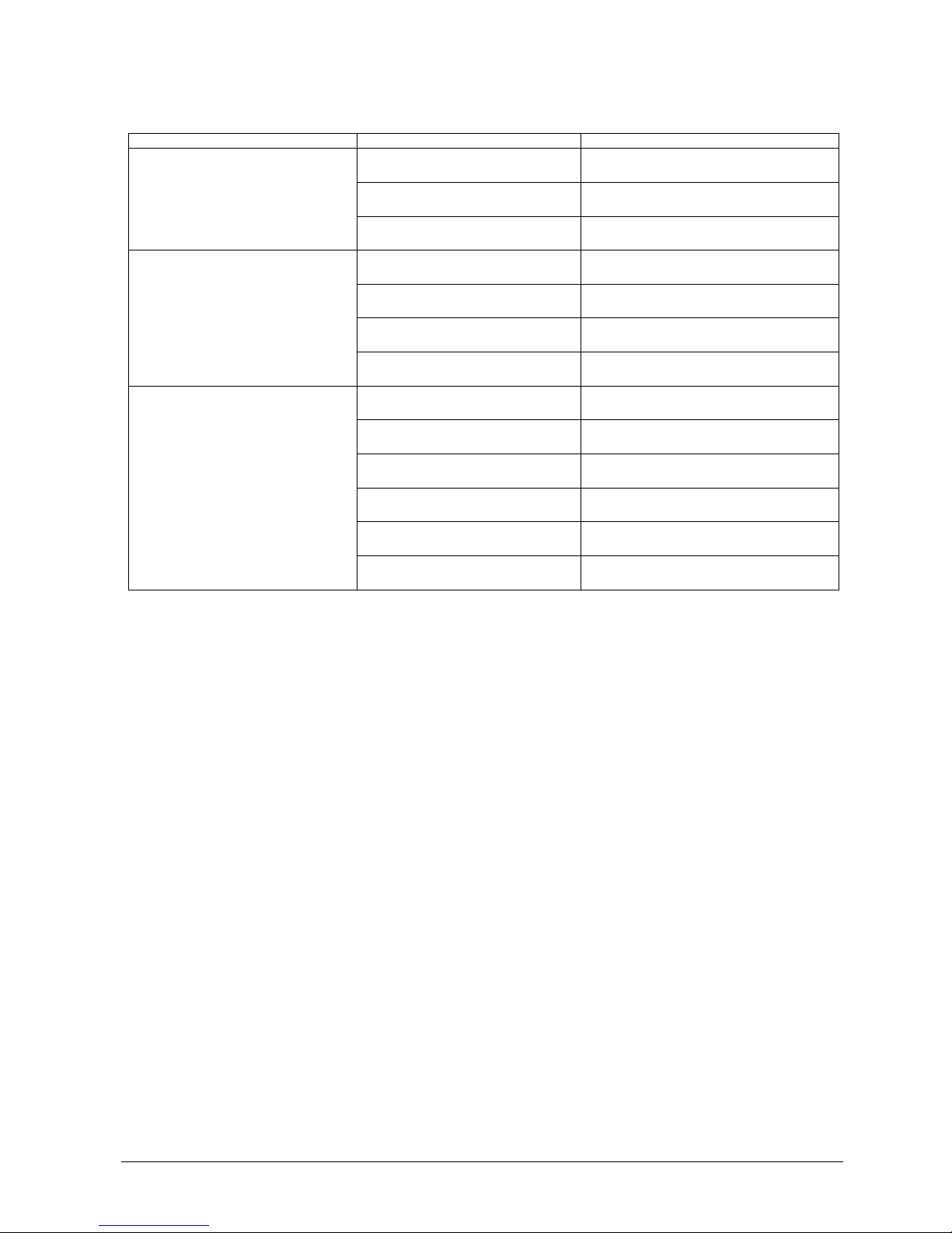
Chemical Reduction Nozzles
Before the system is started the dosage of the detergent must be determined. The following list shows the
approximate dosage percentages for chemistry:
Colour Dosage Order no.
[%]
Purple 0.8 294-000010
Blue 1.3 294-000003
Dark brown 1.7 294-000011
Orange 2.3 294-000012
Brown (mounted by delivery) 3.7 294-000013
White 5.3 294-000005
Red 7.4 294-000004
The above mentioned dosage percentages for chemistry are intended values and are depending on the type and
viscosity of the detergent.
If a different dosing percentage than the one supplied by the nozzle for chemical limitation—being installed from the
factory—should be required, the suction filter at the end of the hose for detergent must be disassembled. The chemical
limit nozzle must be screwed off the suction filter and another nozzle can be mounted instead.

Version 13 (08.2018. EN) (S2)
Page 48 of 48
System Cleaners A/S
Halkjærvej 17
DK-9200 Aalborg SV
Denmark
Tel.: +45 96 34 04 04
Fax.: +45 98 79 19 42
info@systemcleaners.com
www.systemcleaners.com
Please note:
We reserve the right to make alterations to the technical specifications without notice.
 Loading...