

Page 1

Version 9 (02.2018. EN)
MANUAL
MS5 and MS7
PS1, PS3, PS5 and PS7
Page 2

Version 9 (02.2018. EN) (MS5, MS7, PS1, PS3, PS5, PS7)
Page 2 of 48
General
For safety during installation and later use it is very important that installation, operating and maintenance
instructions are carefully followed.
You are requested to keep this instruction manual at a location where it will be available at all times, and it should be
submitted to the person who is responsible for this product. In the event that the instruction manual is lost, you are
welcome to order a new one from your dealer.
If any doubt should arise with regard to the content of these instructions, please contact the distributor.
Proper use
System Cleaners’ system is exclusively designed to transport and pressure-increase of water to satellite stations. All
other forms of application or use not within the scope of the above are considered to be improper and inconsistent
with the requirements and regulations, and may lead to hazardous situations.
System Cleaners A/S cannot be held liable for consequential damage resulting from improper use of the equipment.
Proper use includes the following:
The instructions, regulations and recommendations concerning the system stated in the instruction manual
Observance of the specified inspection and maintenance intervals
Correct maintenance of good operating condition of the system
Observance of the specified environmental and operating conditions
Proper use also includes observance of all information that is stated in this instruction manual. This applies in
particular to the specified safety instructions.
Liability
Each user must handle and use the system in a responsible manner.
It is therefore of great importance that this instruction manual is available to the sanitation employee concerned at all
times.
Safety
The design of the system complies with generally accepted technical regulations and provisions concerning the working
environment and accident prevention. Despite this, risks can occur during use that can lead to physical inconvenience
for the user or a third party or have an impact on the machine or other equipment.
The system must therefore be in prime technical condition before use and may only be used in accordance with its
purpose and with strict observance of the safety requirements and operating instructions. In particular, malfunctions
and irregularities that can affect safety must be remedied immediately.
Warranty
For a period of 24 months from the date of delivery, your dealer will honor a warranty on parts that do not function
properly due to material defects or manufacturing faults. The warranty does not cover wearing parts. The warranty will
cover replacement or repair of the defective part. Costs with regard to dismantling, forwarding and reassembly are
defrayed by the purchaser. Any return shipments from System Cleaners A/S following completed repairs are defrayed
by System Cleaners A/S. The defective parts remain the property of System Cleaners A/S.
Claims that may be made for legal reasons, ordinary wear and tear, as well as damage to parts that can be attributed
to negligent or improper handling are not covered by the warranty. The warranty will be void if the system has been
exposed to frost. The warranty will also be void if modifications or repairs have been carried out by unauthorized
personnel. Warranty claims will only be accepted if they are reported to System Cleaners A/S immediately after
damage has been discovered. The warranty is terminated if there is a change of ownership of the machine. System
Cleaners A/S and its dealers cannot be held liable for personal injury, damage to equipment, loss of earnings,
including production losses, losses to stock or similar that may have arisen as a result of defects or delayed delivery of
the sold product, irrespective of the cause, including manufacturing faults or material defects. In addition, please refer
to our general terms and conditions of sales and delivery.
Page 3

Version 9 (02.2018. EN) (MS5, MS7, PS1, PS3, PS5, PS7)
Page 3 of 48
Disposal
Please be aware of the following applicable provisions: the equipment must be disposed of according to its nature and
applicable requirements, e.g. electrical scrap, synthetic material, stainless steel, brass, etc.
Labelling
The system is equipped with a type plate containing technical data.
The type plate is located on a fixed part of the system.
Declaration of conformity
We declare that this product is in conformity with the following directives:
2006/42/EC Directive on Machinery
2014/35/EU Low Voltage Directive
2014/30/EU EMC Directive
Per Kjøller
Development Manager
Page 4

Version 9 (02.2018. EN) (MS5, MS7, PS1, PS3, PS5, PS7)
Page 4 of 48
DESCRIPTION
Main station (MS5 and MS7)
A main station has a built-in pump, a built-in satellite and is connected to electrical power, water mains, a number of
chemicals and compressed air. It supplies pressurized water to the built-in satellite and a number of external satellites.
With the built-in satellite it is possible for one operator to rinse, foam or disinfect (depending on model) while
pressurized water is supplied to external satellites.
The outlet pressure is constant regardless of the number of connected satellites in use.
The pump is protected from dry running in case of insufficient water supply.
The main station is protected from excessive water temperatures by a switch in the pump.
Pump station (PS1, PS3, PS5 and PS7)
A pump station has a built-in pump and is connected to electrical power, water mains and supplies pressurized water
to a number of satellites.
The outlet pressure is constant regardless of the number of connected satellites in use.
The pump is protected from dry running in case of insufficient water supply.
The pump station is protected from excessive water temperatures by a switch in the pump.
Page 5
Version 9 (02.2018. EN) (MS5, MS7, PS1, PS3, PS5, PS7)
Page 5 of 48
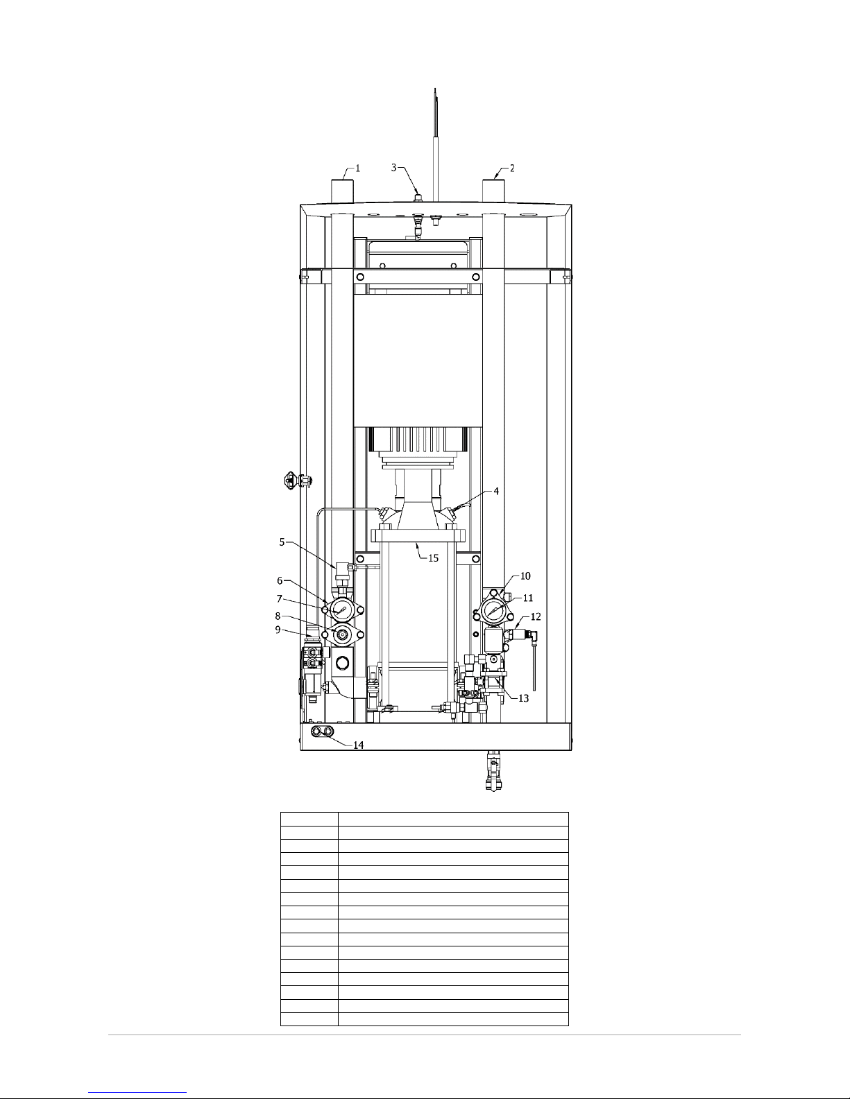
Pos.
Description
1
Input 1.1/2”
2
Outlet 1.1/2”
3
Air connection ø8
4
Temperature switch
5
Pressure switch
6
Filter
7
Input pressure
8
Flow switch
9
Pneumatic assembly
10
Non-return valve
11
Outlet pressure
12
Pressure transmitter
13
Injector system
14
Start/Stop
15
Pump
Page 6

Version 9 (02.2018. EN) (MS5, MS7, PS1, PS3, PS5, PS7)
Page 6 of 48
INSTALLATION
Storage
The machine must not be exposed to frost unless it has been emptied of water (frost protected). Even brief periods of
exposure to frost may cause damage to the equipment.
Store the equipment in a frost-free room in the original packing.
Installation
Place the equipment in a frost-free room, well protected from the sun and place it on a hard surface.
Make sure that, in the event of failing non-return valves in the air and water supply, there are suitable back-flow
preventers fitted.
Local regulations may require installation of a back-flow protecting device to prevent compressed air or chemicals
getting into the water supply.
Piping
The piping should be made from materials suitable for the media in the pipes, the maximum pressure and
temperature.
It is the fitter’s responsibility to ensure that the piping including all armatures conform to local regulations.
The installation must be performed such that forces from pipes etc. are not transferred to the equipment during and
after fitting, as this may result in leaks or damage the equipment.
Select a pipe size so that the flow velocity in the pipe is up to 3 meters/second (10 feet/second). This gives a normally
accepted pressure loss and low noise from the flow.
In order to facilitate maintenance of the equipment, it is recommended to fit a shut-off valve in the pipelines
immediately at the connections for water.
Pipe supports
Always use pipe supports designed for the pipe size and material and maximum working pressure and temperature.
Page 7
Version 9 (02.2018. EN) (MS5, MS7, PS1, PS3, PS5, PS7)
Page 7 of 48
Page 8

Version 9 (02.2018. EN) (MS5, MS7, PS1, PS3, PS5, PS7)
Page 8 of 48
COMMISSIONING
Flushing
Pipes etc. must be flushed efficiently before connecting the unit.
Before commencing operation on the unit or following repair work, the unit must be flushed thoroughly to remove any
impurities or foreign bodies.
Bleeding
Prior to starting the system for the first time and following any interruption of the water supply, the pump and
pipelines must be bled thoroughly to avoid damage to the pump’s shaft seal.
Air pockets in the pipes may cause destructive water hammer when the pump starts.
Disinfection
Local specifications may require disinfection of the wetted parts like internals of pipes and pumps before use to avoid
contamination of newly cleaned surfaces.
Dosing (MS5 and MS7)
Adjust the dosing according to the chemical supplier’s recommendations.
Always calibrate and, if required, document the dosing on a regular basis.
Air (MS5 and MS7)
Adjust the air pressure until a satisfactory foam quality is achieved.
Note that good foam quality depends on the mixture of water, chemical and air and getting a perfect result requires
some adjustments of the mixing ratios.
OPERATION
Safety
It is recommended that suitable working clothes be worn. For protection against certain types of detergents, always
use protective goggles, respiratory protective equipment and rubber gloves.
It is recommended that non-slip footwear be worn since the floor can be slippery due to the presence of water and
foam.
This system may only be operated, maintained and – not least - repaired by persons who are familiar with the system
and properly trained to carry out the job concerned.
It is the customer’s responsibility that these installation and operating instructions are supplemented by in-house
instructions concerning inspection and reporting, industrial management, personnel training, etc.
Do not carry out any work if you are unsure of the consequences or are insufficiently skilled to carry it out. If in doubt,
you should contact your superior or your agent in advance.
Never direct the water jet at other persons.
Never direct the water jet at electrical installations.
Check that couplings “lock” when hoses and nozzles are fitted. If possible, practise this procedure before operation.
Always relieve the pressure in the rinsing hose by opening the low-pressure gun or valve after the water supply has
been shut off before dismantling the couplings and removing the hose.
During operation of the system, ensure that the low-pressure gun/valve is closed before releasing the handle.
When the low-pressure gun or valve is opened, the water jet will result in a certain amount of counter-pressure.
Therefore make sure that you hold the handle firmly and have a firm foothold.
Before removing the cabinet, the power supply must be switched off.
Page 9

Version 9 (02.2018. EN) (MS5, MS7, PS1, PS3, PS5, PS7)
Page 9 of 48
Safety precautions and safety devices must comply with national regulations applicable at any time.
Internally, protection corresponds to IP 55. On a number of components hazardous voltages can occur. During
operation the cabinet must always be closed.
Never insert or remove a plug from an electrical socket unless the power has been switched off.
System Cleaners low-pressure systems may only be used in conjunction with soaps and chemicals that are approved
for cleaning within the food or transport industries.
Soaps and chemicals that are classified as highly corrosive, toxic or which pose a health risk to humans or animals
may not be used.
The system must not be used together with solvents or volatile liquids that pose a health risk or are inflammable.
In the event that the system is used with non-approved soaps, chemicals or solvents, System Cleaners A/S disclaims
all liability.
If in doubt, please contact your soap or chemical supplier and read the supplier manual.
In the event that you use the system with chemicals that require mandatory labelling, or if the water temperature
exceeds 50°C, a low-pressure gun with an automatic closing device must be used.
Start
The system starts automatically in the event of falling pressure in the outlet pipe like when the operator opens the low
pressure gun or valve.
Pressure setting (remote control)
Use the optional R100 remote control or the optional Bluetooth dongle to change the pressure set point. Be careful not
to set the pressure below 15 bar (217 psi) if the unit is supplying a satellite – both built-in and external - as this may
compromise the function of the injector.
Stop
The system stops automatically shortly after water is no longer being used like when the operator closes the low
pressure gun or valve.
Leaks
If there are leaks in the system’s non-return valve, pipelines or satellites, the pump will start although there is no
water being used.
Flush injector system (MS5 and MS7)
After each use flush the injector system with warm water to avoid clogging of the injector.
MAINTENANCE
Water filter
Depending on the mains water quality it may be necessary to clean the water filter on a regular basis to prevent the
pump from stopping.
Flow switch
The flow switch does not require maintenance.
Shaft seal
The shaft seal does not require maintenance. Leaks are normally a sign of dry running caused by insufficient water
supply to the pump.
Water non-return valve
Water non-return valves are critical wear parts and should be replaced yearly.
Page 10

Version 9 (02.2018. EN) (MS5, MS7, PS1, PS3, PS5, PS7)
Page 10 of 48
Pump, motor and frequency drive
Scaling compromises the function of the pump and de-scaling following the chemical supplier’s guidelines may be
necessary on a regular basis.
Motor and frequency drive do not require maintenance.
Air filter (MS5 and MS7)
Depending on the quality of the compressed air it may be necessary to empty condensation collected in the air filter
bowl on a regular basis.
Injector system (MS5 and MS7)
The injector system consists of foot strainer, dosing valve, non-return valve and injector.
Chemical residues compromises the function of the injector and flushing with warm water after each use is required to
maintain trouble free operation.
Depending on the water quality it may be necessary to de-scale the water side of the injector on a regular basis
following the chemical supplier’s guidelines.
Page 11
Version 9 (02.2018. EN) (MS5, MS7, PS1, PS3, PS5, PS7)
Page 11 of 48
TROUBLE SHOOTING MS5 and MS7
Fault
Cause
Remedy
No water or insufficient water at the
nozzle when rinsing
Function selector is in closed
position
Turn the function selector switch to the
desired function
Insufficient water supply to the unit
Make sure that the water supply is as
described in the technical specifications
Valve at the end of the hose not
open
Open valve
The unit does not suck up detergent
Function selector is not in the
correct position
Turn function selector switch to desired
function
Suction filter or chemical restrictor
are blocked by chemical residue
Clean suction filter or chemical
restrictor
Water pressure is too low
Make sure water supply is as
described in the technical specifications
Suction filter is above the fluid level
in chemical container
Position the suction filter below fluid level
Poor foam quality
Chemical product is not a foaming
product
Change to a foaming chemical
Incorrect dosing
Adjust the dosing according to chemical
supplier’s specifications
Suction filter or chemical restrictor
are blocked by chemical residue
Clean the suction filter or chemical
restrictor
Water pressure is too low
Make sure that the water supply is as
described in the technical specifications
Air pressure too low
Increase air pressure
Non-original foam nozzle fitted
Replace with original white foam nozzle
Fault
Cause
Remedy
Rinse pressure too low
Pump station not started
Press green button
Too many simultaneous users
Reduce the number of simultaneous
users
Pump stopped due to inlet pressure
less than 1.5 bar (23 psi)
Increase inlet pressure to between 1.5
and 10 bar (23 and 145 psi)
The device will not start
Valve in inlet or outlet closed
Open valves
Inlet water pressure less than 1.5
bar (23 psi)
Increase inlet pressure to between 1.5
and 10 bar (23 and 145 psi)
TROUBLE SHOOTING PS1, PS3, PS5 and PS7
Fault
Cause
Remedy
Rinse pressure too low
Pump station not started
Press green button
Too many simultaneous users
Reduce the number of simultaneous
users
Pump stopped due to inlet pressure
less than 1.5 bar (23 psi)
Increase inlet pressure to between 1.5
and 10 bar (23 and 145 psi)
The device will not start
Valve in inlet or outlet closed
Open valves
Inlet water pressure less than 1.5
bar (23 psi)
Increase inlet pressure to between 1.5
and 10 bar (23 and 145 psi)
Page 12
Version 9 (02.2018. EN) (MS5, MS7, PS1, PS3, PS5, PS7)
Page 12 of 48
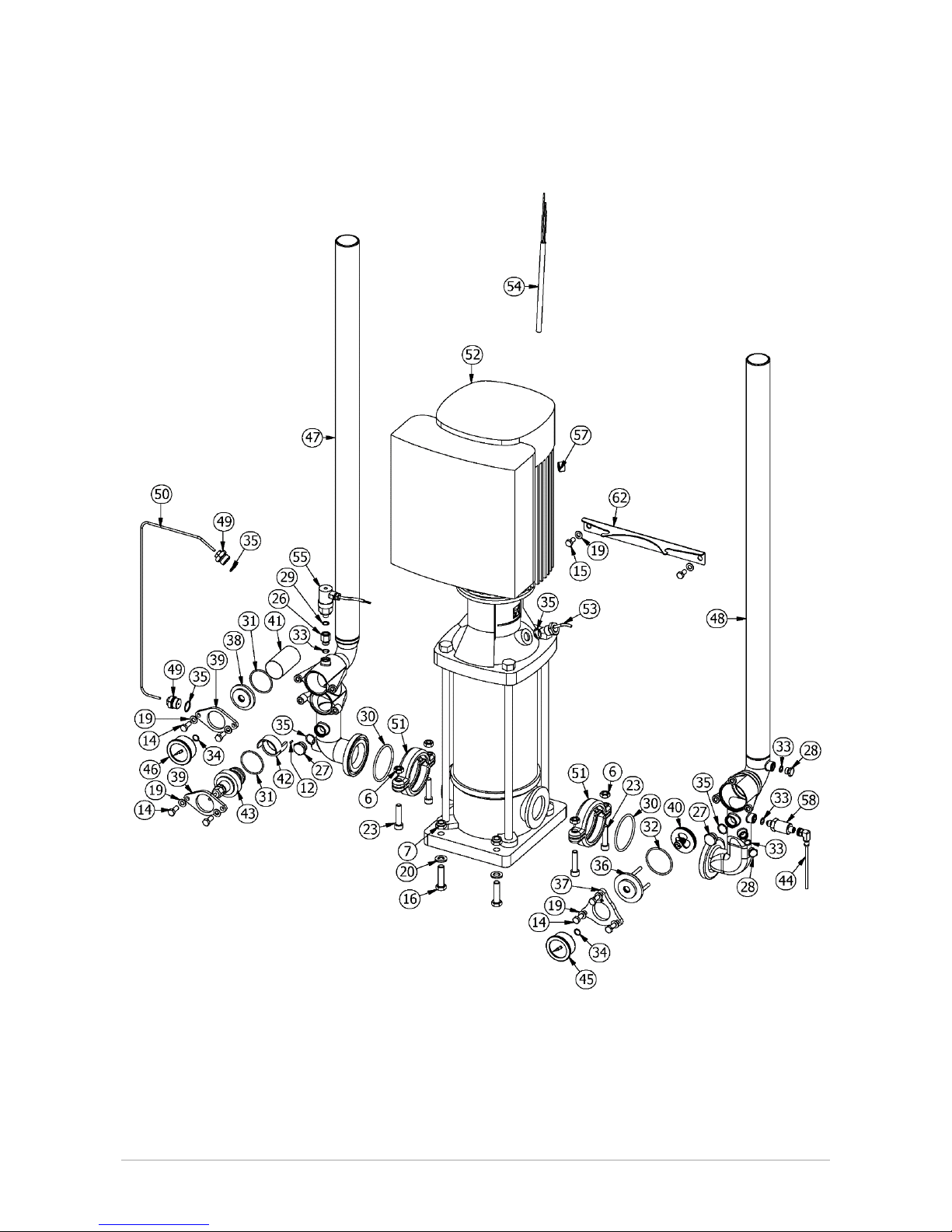
Spare parts machine
Page 13
Version 9 (02.2018. EN) (MS5, MS7, PS1, PS3, PS5, PS7)
Page 13 of 48
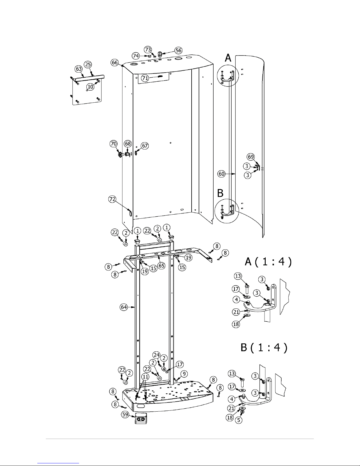
Spare parts Cabinet
Page 14

Version 9 (02.2018. EN) (MS5, MS7, PS1, PS3, PS5, PS7)
Page 14 of 48
Pos.
Part no.
Description
Material
Version
1
04-000072
Plastic knob 30mm
Plastic
All
2
04-000178
Spacer ø25x25,75 sort
PVC-U
All
3
08-000502
Lock nut M5
A2
All
4
08-000504
Cap nut M5
A2
All
5
08-000602
Lock nut M6
A2
All
6
08-000801
Nut M8
A2
MS5, PS1, PS3, PS5
6
08-001001
Nut M10
A2
MS7, PS7
7
08-001201
Lock nut M12
A2
All
8
08-100515
Screw buttonhead M5x10mm
A2
All
9
08-100610
Coach screw M6x80mm
A2
All
10
08-100801
Coach screw M8x60
A2
All
11
08-104015
Screw for plastic 5x12
A2
All
12
08-105020
Spring pin ø3x8 RF
A2
All
13
08-200602
Set screw M6x20
A2
All
14
08-200805
Set screw M8x20
A2
All
15
08-200808
Set screw M8x16
A2
All
16
08-201207
Set screw M12x40
A2
MS5, PS1, PS3, PS5
16
08-201211
Set screw M12x45
A2
MS7, PS7
17
08-300602
Disc washer ø6
A2
All
18
08-300605
Disc washer ø6
Nylon
All
19
08-300803
Plane washer ø8
A2
All
20
08-301202
Disc washer ø12
A2
All
21
08-800505
Cheese-head screw M5x10
A2
All
22
08-800601
Cheese-head screw M6x20
A2
All
23
08-800835
Cheese-head screw M8x35
A2
MS5, PS1, PS3, PS5
23
08-801003
Cheese-head screw M10x45
A2
MS7, PS7
24
08-900008
Rawlplugs S 8
PVC
All
25
08-900010
Rawlplugs S 10
PVC
All
26
15-200082
Socket 1/4"x1/8"
AISI 316
All
27
16-501200
Plug 1/2"
AISI 304
All
28
16-501403
Plug 1/4" 9mm
AISI 316
All
29
17-000032
O-ring 10,1x1,6 NBR 70 shore
NBR
All
30
17-010010
O-ring 46x3
NBR
MS5, PS1, PS3, PS5
30
17-010011
O-ring 70x4
NBR
MS7, PS7
31
17-020004
O-ring 47,29x2,62 EPDM 70 sh
EPDM
All
32
17-020017
O-ring 55,2x3 EPDM
EPDM
All
33
17-020055
O-ring 10x2 70 shore
EPDM
All
34
17-020056
O-ring 11x1,5 70 shore
EPDM
All
35
17-020080
O-ring 18x2 70 shore
EPDM
All
36
20-010006
Cap for Non-return valve
AISI 303
All
37
20-010007
Flange for Non-return valve
AISI 303
All
38
20-010008
Cap for Filter
AISI 303
All
39
20-010009
Flange for Filter
AISI 303
All
40
20-200200
Non-return valve 1.1/2"
AISI 304/NBR
All
41
20-510040
Filter insertion 1.1/2" 800 µm
AISI 304
All
42
21-000022
Insert for flow-switch
AISI 303
All
43
21-000025
Flow switch 1.1/2"
-
All
44
21-000102
Angle connector M12x5m
-
All
45
22-000042
Gauge ø50 0-60 bar SS
AISI 304/brass/glycerine
All
46
22-000044
Gauge ø50, -1-16 bar SS
AISI 304/brass/glycerine
All
47
25-050019
Inlet pipe 1.1/4"/1.1/2" BSP
AISI 304
MS5, PS1, PS3, PS5
BSP
47
25-050020
Inlet pipe 1.1/2" BSP
AISI 304
MS7, PS7, BSP
47
25-050027
Inlet pipe 1.1/4"/1.1/2" NPT
AISI 316
MS5, PS1, PS3, PS5
NPT
47
25-050028
Inlet pipe 1.1/2" NPT
AISI 316
MS7, PS7, NPT
48
25-250020
Outlet pipe 1.1/4"/1.1/2" BSP
AISI 304
MS5, PS1, PS3, PS5
BSP
48
25-250021
Outlet pipe 1.1/2" BSP
AISI 304
MS7, PS7, BSP
48
25-250026
Outlet pipe 1.1/4"/1.1/2" NPT
AISI 316
MS5, PS1, PS3, PS5
NPT
Page 15

Version 9 (02.2018. EN) (MS5, MS7, PS1, PS3, PS5, PS7)
Page 15 of 48
48
25-250027
Outlet pipe 1.1/2" NPT
AISI 316
MS7, PS7, NPT
49
26-100100
Clamping ring fitting 1/2"x4
AISI 303
All
50
26-100121
Vent pipe model 5
AISI 304
MS5, PS1, PS3, PS5
50
26-100131
Vent pipe model 7
AISI 304
MS7, PS7
51
30-740483
Flexi clamps ø48,3
-
MS5, PS1, PS3, PS5
51
30-740761
Flexi clamps ø76,1
-
MS7, PS7
52
06-000315
Pumpe CRNE 3-9 2,2 kW
-
PS1
3x380-500v/50-60Hz
52
06-000600
Pumpe CRNE 3-9 4 kW
-
PS3
3x380-500v/50-60Hz
52
06-000525
Pumpe CRNE 5-14 6 kW
-
MS5, PS5
3x380-500v/50-60Hz
52
06-000005
Pumpe CRNE 10-9 7,5 kW
-
MS7, PS7
3x380-500v/50-60Hz
53
32-000090
Temperature switch 88°C 1/2"NC
AISI 304
All
54
35-411001
Cable 4x1,5mm² CE 3m
-
MS5, PS1, PS3, PS5
3x400V/50Hz
54
35-411011
Cable 4x1,5mm² 3 m AWG16
-
MS5, PS5
3x460V/60Hz
54
35-411000
Cable 4x2,5mm² CE
-
MS7, PS7
3x400V/50Hz
54
35-411010
Cable 4x2,5mm² CSA
-
MS7, PS7
3x460V/60Hz
55
35-600064
Pressure switch 1/8" 0,1-2bar NO
-
All
56
35-700201
Screwed cable connection
Plastic
All
57
35-712498
Multiple packing M25x1,5 4x6,5mm
Plastic
All
58
36-100090
Pressure transmitter 60 bar
-
All
59
36-800015
On/off buttons G5
-
All
60
41-231001
Door 1000mm G5
AISI 304
All
61
42-600047
Hinge for cabinet 1000 mm
AISI 304
All
62
42-600069
Attachment bracket
AISI 304
MS5, PS1, PS3, PS5
62
42-600070
Attachment bracket
AISI 304
MS7, PS7
63
43-100070-01
Wall bracket
AISI 304
All
64
46-023010
Pump bracket 1000 mm G5 IE5
AISI 304
All
65
46-160160
Top plate for MS/AM IE5
AISI 304
All
66
46-401004
Housing 1000mm IE5
AISI 304
All
67
72-000030
Nut for lock
Nylon
All
68
72-000040
Lock with hook
AISI 304/Plastic
All
69
72-000050
Strike plate - All
70
72-100010
Key for housing
Plastic
All
71
35-700200
Cablenut M20x1,5
Brass
All
72
04-000223
Blind plug ø32,5 black
Plastic
PS1, PS3, PS5, PS7
73
04-000012
Blind plug ø15 black
polyethylene
PS1, PS3, PS5, PS7
74
010-200200
Plastic plug ø23xø20mm
Nylon
PS1, PS3, PS5, PS7
Page 16

Version 9 (02.2018. EN) (MS5, MS7, PS1, PS3, PS5, PS7)
Page 16 of 48
Injector concentrated MS5 and MS7
Page 17

Version 9 (02.2018. EN) (MS5, MS7, PS1, PS3, PS5, PS7)
Page 17 of 48
Injector Pre-diluted MS5 and MS7
Page 18

Version 9 (02.2018. EN) (MS5, MS7, PS1, PS3, PS5, PS7)
Page 18 of 48
Pos.
Part no.
Description
Material
Version
1
15-000010
Adapter ø8x1/4" NPT SS
AISI 304
NPT
2
15-000071
Bulkhead connection air 8mm
Plastic
All
3
15-000061
Air fitting 8x8 elbow
Plastic
All
4
17-020080
O-ring 18x2 70 shore
EPDM
All
5
16-900045
Union nut for Non-return valve
AISI 303
All
6
25-000595
Inlet pipe 1/2" MS 5
AISI 303
MS5
6
25-000594
Inlet pipe 1/2" MS 7
AISI 303
MS7
7
17-030129
O-ring 32x1,5 Viton 75 sh
Viton
All
8
20-200410
Non-return valve 1/2"
AISI 304/NBR
All
9
25-100510
Flanged nipple M24x1
AISI 316
All
10
16-110013
Adapter injector
AISI 316
Pre-diluted
11
20-000283
Ball valve 1/2"
-
All
12
15-090402
Color ring 4mm green
Plastic
All
13
08-800807
Cheese-head screw M8x50
A2
All
14
25-200350
Outlet pipe 1/2"
AISI 316
All
15
17-000083
O-ring 15,54x2,62
NBR
All
16
16-800070
Outlet nipple 1/2"x67 E/I
AISI 316
All
17
20-000220
Ball valve 1/2" (blue)
AISI 316
All
18
30-000050
Outlet coupling 1/2"
Special stainless
All
19
15-090406
Color ring 4mm grey
Plastic
All
20
27-010141
Injector with 3 connections
AISI 316
All
21
17-000032
O-ring 10,1x1,6 NBR 70 shore
NBR
All
22
55-110080
Air hose ø4mm black
PA12
All
23
15-010161
Air fitting ø2,0
Nickel-plated brass/Plastic
All
24
15-090606
Color ring 6mm green
Plastic
All
25
55-100034
Air hose 6x430 green
PA12
All
26
17-030008
O-ring 7,65x1,78 Viton 70 sh
Viton
All
27
27-200020
Water nozzle ø1,8
AISI 316
All
28
17-000132
O-ring 9,92x2,62
NBR
All
29
15-020050
Elbow 1/8"x4
Plastic/Brass
All
30
16-110012
Adaptor for injector
AISI 316
Concentrated
31
08-100515
Screw buttonhead M5x10mm
A2
All
32
20-300141
Filter 1/4"
Plastic
All
33
15-090603
Color ring 6mm red
Plastic
All
34
15-010010
Air fitting 1/4"x6 elbow
Nickel-plated brass/Plastic
All
35
69-400100
Label Quickguide
-
All
36
42-200120
Bracket for pneumatics G5
AISI 304
All
37
20-300080
Air regulator without filter
Plastic
All
38
16-400040
Extension nipple 1/4"x20
Nickel-plated brass
All
39
15-000011
Air fitting 1/4"x8 elbow
Nickel-plated brass/Plastic
All
40
55-100044
Air hose 8x1200 black
PA12
All
41
16-501802
Plug 1/8"
AISI 316
All
42
17-000072
Gasket 1/8"
Nylon
All
43
22-000071
Gauge ø20 0-10 bar
AISI 304/brass/glycerine
All
44
25-100522
Elbow for injector
AISI 316
All
45
16-800090
Nipple for needle valve
AISI 316
Pre-diluted
46
16-900010
Nut 3/8"
AISI 316
Pre-diluted
47
15-020081
Air fitting M7x4 elbow
Nickel-plated brass/Plastic
Pre-diluted
48
20-000810
Chemical valve, pneumatic Viton
AISI 316/Viton
Pre-diluted
49
17-020055
O-ring 10x2 70 shore
EPDM
Pre-diluted
Page 19

Version 9 (02.2018. EN) (MS5, MS7, PS1, PS3, PS5, PS7)
Page 19 of 48
Spare parts Functions (MS5 and MS7)
Function F
Function F D
Page 20

Version 9 (02.2018. EN) (MS5, MS7, PS1, PS3, PS5, PS7)
Page 20 of 48
Function F F
Function F F D
Page 21

Version 9 (02.2018. EN) (MS5, MS7, PS1, PS3, PS5, PS7)
Page 21 of 48
Function F F F
Page 22

Version 9 (02.2018. EN) (MS5, MS7, PS1, PS3, PS5, PS7)
Page 22 of 48
Function PF
Page 23

Version 9 (02.2018. EN) (MS5, MS7, PS1, PS3, PS5, PS7)
Page 23 of 48
Function PF PD
Page 24

Version 9 (02.2018. EN) (MS5, MS7, PS1, PS3, PS5, PS7)
Page 24 of 48
Function PF PF
Page 25

Version 9 (02.2018. EN) (MS5, MS7, PS1, PS3, PS5, PS7)
Page 25 of 48
Function PF PF PD
Page 26

Version 9 (02.2018. EN) (MS5, MS7, PS1, PS3, PS5, PS7)
Page 26 of 48
Function PF PF PF
Page 27

Version 9 (02.2018. EN) (MS5, MS7, PS1, PS3, PS5, PS7)
Page 27 of 48
Function PF D
Page 28

Version 9 (02.2018. EN) (MS5, MS7, PS1, PS3, PS5, PS7)
Page 28 of 48
Function PF F
Page 29

Version 9 (02.2018. EN) (MS5, MS7, PS1, PS3, PS5, PS7)
Page 29 of 48
Function PF F D
Page 30

Version 9 (02.2018. EN) (MS5, MS7, PS1, PS3, PS5, PS7)
Page 30 of 48
Function PF PF D
Page 31

Version 9 (02.2018. EN) (MS5, MS7, PS1, PS3, PS5, PS7)
Page 31 of 48
Function PF PF F
Page 32

Version 9 (02.2018. EN) (MS5, MS7, PS1, PS3, PS5, PS7)
Page 32 of 48
Function PF PD D
Page 33

Version 9 (02.2018. EN) (MS5, MS7, PS1, PS3, PS5, PS7)
Page 33 of 48
Function PF PD F
Page 34

Version 9 (02.2018. EN) (MS5, MS7, PS1, PS3, PS5, PS7)
Page 34 of 48
Separate F- injector
Page 35

Version 9 (02.2018. EN) (MS5, MS7, PS1, PS3, PS5, PS7)
Page 35 of 48
Separate D-injector
Page 36

Version 9 (02.2018. EN) (MS5, MS7, PS1, PS3, PS5, PS7)
Page 36 of 48
Pos.
Part no.
Description
Material
Version
1
010-200200
Plastic plug ø23xø20mm
Nylon
All
2
20-400056
Dosing valve concentrated
AISI 316/Viton
All
3
20-400054
Dosing valve pre-diluted
AISI 316/Viton
All
4
04-000082
Diaphragm nipple
EPDM
All
5
04-000232
Cone ø12 black
Plastic
All
6
08-200606
Set screw M6x16
A2
All
7
08-300602
Disc washer ø6
A2
All
8
15-010040
Air fitting ø6 Y
Plastic
All
9
15-010161
Air fitting ø2,0
Nickel-plated brass/Plastic
All
10
15-020081
Air fitting M7x4 elbow
Nickel-plated brass/Plastic
All
11
15-090400
Color ring 4mm white
Plastic
All
12
15-090403
Color ring 4mm red
Plastic
All
13
15-090404
Color ring 4mm blue
Plastic
All
14
15-090405
Color ring 4mm yellow
Plastic
All
15
15-090606
Color ring 6mm green
Plastic
All
16
15-100082
Hexagon nipple 1/4"
AISI 316
All
17
15-300012
Hose clip for 1/4"
PVC
All
18
15-901400
Closing cap 1/4"
Nickel-plated brass
All
19
16-100100
Adaptor 1/8"xM12x1
AISI 316
All
20
16-500010
Plug M12x1
AISI 316
All
21
16-800070
Outlet nipple 1/2"x67 E/I
AISI 316
All
22
17-000032
O-ring 10,1x1,6 NBR 70 shore
NBR
All
23
17-000062
O-ring 18x2
NBR
All
24
17-000132
O-ring 9,92x2,62
NBR
All
25
17-030008
O-ring 7,65x1,78 Viton 70 sh
Viton
All
26
17-030018
O-ring 11x1,5 Viton 70 shore
Viton
All
27
20-000220
Ball valve 1/2" (blue)
AISI 316
All
28
20-000221
Ball valve 1/2" (Yellow)
AISI 316
All
29
20-000810
Chemical valve, pneumatic Viton
AISI 316/Viton
All
30
20-300000-02
Panel nut function selector
Plastic
All
31
20-301400
Selector switch F
-
F
32
20-301410
Selector switch F D
-
F D
32
20-301420
Selector switch F F
-
F F
32
20-301430
Selector switch F F D
-
F F D
32
20-301440
Selector switch F F F
-
F F F
32
20-301450
Selector switch PF
-
PF
32
20-301460
Selector switch PF PD
-
PF PD
32
20-301470
Selector switch PF PF
-
PF PF
32
20-301480
Selector switch PF PF PD
-
PF PF PD
32
20-301490
Selector switch PF PF PF
-
PF PF PF
32
20-301500
Selector switch PF D
-
PF D
32
20-301510
Selector switch PF F
-
PF F
32
20-301520
Selector switch PF F D
-
PF F D
32
20-301530
Selector switch PF PF D
-
PF PF D
32
20-301540
Selector switch PF PF F
-
PF PF F
32
20-301550
Selector switch PF PD D
-
PF PD D
32
20-301560
Selector switch PF PD F
-
PF PD F
33
20-304002
Handle, F
ABS
F
33
20-304003
Handle, F D
ABS
F D
33
20-304004
Handle, F F
ABS
F F
33
20-304005
Handle, F F D
ABS
F F D
33
20-304006
Handle, F F F
ABS
F F F
33
20-304007
Handle, PF
ABS
PF
33
20-304008
Handle, PF PD
ABS
PF PD
33
20-304009
Handle, PF PF
ABS
PF PF
33
20-304011
Handle, PF PF PD
ABS
PF PF PD
33
20-304012
Handle, PF PF PF
ABS
PF PF PF
33
20-304013
Handle, PF D
ABS
PF D
33
20-304014
Handle, PF F
ABS
PF F
33
20-304015
Handle, PF F D
ABS
PF F D
33
20-304016
Handle, PF PF D
ABS
PF PF D
Page 37

Version 9 (02.2018. EN) (MS5, MS7, PS1, PS3, PS5, PS7)
Page 37 of 48
33
20-304017
Handle, PF PF F
ABS
PF PF F
33
20-304018
Handle, PF PD D
ABS
PF PD D
33
20-304019
Handle, PF PD F
ABS
PF PD F
34
25-000620
Inlet pipe 1/4" BSP
AISI 316
BSP
34
25-000621
Inlet pipe 1/4" NPT
AISI 316
NPT
35
26-000380
Pipe ø6x1
AISI 316
All
36
26-100020
Clamping ring fitting 1/8"x6
AISI 316
All
37
26-100030
Clamping ring fitting 1/8"x6
AISI 316
All
38
27-010111
Injector housing
AISI 316
All
39
27-200020
Water nozzle ø1,8
AISI 316
All
40
27-300040
Suction filter ø6,5
AISI 316
All
41
30-000050
Outlet coupling 1/2"
Special stainless
All
42
55-100030
Air hose 6mm green
PA12
All
43
55-110040
Air hose ø6mm black
PA12
All
44
55-110060
Air hose ø6mm red, m
PA12
All
45
55-110080
Air hose ø4mm black
PA12
All
46
55-110110
Air hose ø4mm red
PA12
All
47
55-110120
Air hose ø4mm blue
PA12
All
48
55-110130
Air hose ø4mm white
PA12
All
49
55-110140
Air hose ø4mm yellow
PA12
All
50
55-110150
Air hose ø4mm green
PA12
All
51
55-110170
Air hose ø4mm grey
PA12
All
52
55-200020
Suction hose 1/4" white, m
PVC
All
53
55-200041
Suction hose 12x6 blue, m
PVC
All
54
55-200051
Suction hose 1/4" red, m
PVC
All
55
55-200061
Suction hose 1/4" yellow
PVC
All
56
55-600015
Hose nipple M12x7,5
AISI 316
All
57
55-600016
Hose nipple 1/4"x7,5
AISI 316
All
58
55-700102
Hose 1/4"x1155
-
All
Page 38

Version 9 (02.2018. EN) (MS5, MS7, PS1, PS3, PS5, PS7)
Page 38 of 48
Accessories
Pos.
Part no.
Description
Material
Version
1
72-100010
Key for housing
Plastic
All
2
53-015303
Rinse pipe 660mm 15/30 BR
-
With manual function
3
57-000050
Nozzle holder
-
With manual function
4
53-015301
Rinse nozzle System 15/30 BR
-
With manual function
5
53-502000
Foam nozzle System 50/200 BR
-
With manual function
6
52-160300
Disinfection nozzle KS60/30
-
With manual function
Page 39

Version 9 (02.2018. EN) (MS5, MS7, PS1, PS3, PS5, PS7)
Page 39 of 48
RECOMMENDED SPARE PARTS
Pos.
Part no.
Description
Material
Version
20-200201
Piston Non-return valve 1.1/2"
AISI 316/EPDM
All
32-300010
Shaft seal cartridge 1/3/5 M3
-
MS5
PS1, PS3, PS5
32-100020
Shaft seal cartridge CR10/15/20
-
MS7
PS7
20-400056
Dosing valve conc.
AISI 316/Viton
MS5
MS7
20-400054
Dosing valve conc.
AISI 316/Viton
MS5
MS7
20-000283
Ball valve 1/2"
-
MS5
MS7
20-200175
Non-return valve DN 20
PPO-GF/EPDM
MS5
MS7
15-010161
Air fitting ø2,0
Nickel-plated brass/Plastic
MS5
MS7
Page 40

Version 9 (02.2018. EN) (MS5, MS7, PS1, PS3, PS5, PS7)
Page 40 of 48
Replacement / cleaning of the filter
Replacement of the non-return valve
Replacement of the flow switch
Pos.
Part no.
Description
Material
1
20-510040
Filter insertion 1.1/2" 800 µm
AISI 304
2
20-200201
Piston Non-return valve 1.1/2"
AISI 316/EPDM
3
21-000025
Flow switch 1.1/2"
-
Page 41

Version 9 (02.2018. EN) (MS5, MS7, PS1, PS3, PS5, PS7)
Page 41 of 48
Fitting kit
Pos.
Qty.
Part no.
Description
Material
Version
1 2 20-000042
Ball valve 1.1/2" (blue)
AISI 316
BSP
1 2 20-000039
Ball valve 1.1/2" (blue) NPT
AISI 316
NPT
2 2 15-800054
Union 1.1/2" m/n PTFE
AISI 316/PTFE
BSP
2 2 15-800056
Union 1.1/2" m/n PTFE NPT
AISI 316/PTFE
NPT
3 1 20-000240
Ball valve 1/4" SS (blue)
AISI 316
BSP
3 1 20-000243
Ball valve 1/4" SS NPT (blue)
AISI 316
NPT
4 1 15-000021
Air fitting 1/4"x8 (inside)
Nickel-plated brass/Plastic
All
5 1 55-100040
Air hose 8mm black
PA12
All
Page 42

Version 9 (02.2018. EN) (MS5, MS7, PS1, PS3, PS5, PS7)
Page 42 of 48
TECHNICAL SPECIFICATIONS
Page 43

Version 9 (02.2018. EN) (MS5, MS7, PS1, PS3, PS5, PS7)
Page 43 of 48
Model
PS1
PS3
Installation
Ambient temperature
3-40°C / 37-104°F
Pump
Pump type
CRNE 3-9J
CRNE 3-9J
Motor power
2.2 kW / 3 HP
4 kW / 5.4 HP
Frequency drive
Integrated in pump motor
Degree of protection
IP 54
Connections
In- and outlet
1½” BSP or NPT
Water, inlet
Pressure
1.5-10 bar / 23-150 psi
Maximum pump cut-out pressure
1.5 bar / 22 psi
Temperature
3-70°C / 37-160°F
Minimum pump cut-out temperature
90°C / 190°F
Minimum recommended flow
4.5 m³/h / 18 USgal/min
4.5 m³/h / 18 USgal/min
Water, outlet
Setpoint
20 bar / 290 psi
Maximum flow at 20 bar (290 psi)
(including 4.0 bar (58 psi) inlet
pressure)
30 liter/min / 7.9 US gal/min
90 liter/min / 23.8 US gal/min
Air, inlet
Pressure
-
-
Minimum flow - -
Electrical 230V
Voltage and frequency
3x208-230V +/- 10% 50-60 Hz
Not available
Current
8 A
Recommended pre-fusing
16 A
Recommended cable cross section
4 x 1.5 mm² / 4 x AWG16
Electrical 400 and 460V
Voltage and frequency
3x380-500V +/- 10% 50-60 Hz
Current
3.4-4.15 A
6.2-7.6 A
Recommended pre-fusing
10 A
16 A
Recommended cable cross section
4 x 1.5 mm² / 4 x AWG16
4 x 1.5 mm² / 4 x AWG14
Chemical
Dosing range - -
Dimensions
Weight
125 kg /
276 lbs
150 kg /
331 lbs
Page 44

Version 9 (02.2018. EN) (MS5, MS7, PS1, PS3, PS5, PS7)
Page 44 of 48
Model
PS5
MS5
PS7
MS7
Installation
Ambient temperature
3-40°C / 37-104°F
Pump
Pump type
CRNE 5-14J
CRNE 10-9J
Motor power
6 kW / 8 HP
7.5 kW / 10 HP
Frequency drive
Integrated in pump motor
Degree of protection
IP 54
Connections
In- and outlet
1½” BSP or NPT
Water, inlet
Pressure
1.5-10 bar / 23-150 psi
Maximum pump cut-out pressure
1.5 bar / 23 psi
Temperature
3-70°C / 37-160°F
Minimum pump cut-out temperature
90°C / 190°F
Minimum recommended flow
12 m³/h / 52.8 USgal/min
15 m³/h / 66 USgal/min
Water, outlet
Setpoint
20 bar / 290 psi
Maximum flow at 20 bar (290 psi)
(including 4.0 bar (58 psi) inlet pressure)
150 liter/min / 39.6 US gal/min
200 liter/min / 52.8 USgal/min
Air, inlet
Pressure
-
5-10 bar /
72-145 psi
-
5-10 bar /
72-145 psi
Minimum flow
-
150 liter/min /
5.3 cfm
-
200 liter/min /
7.1 cfm
Electrical 400 and 460V
Voltage and frequency
3x380-500V +/- 10% 50-60 Hz
Current
9.0-11.5 A
11.2-14.1 A
Recommended pre-fusing
20 A
32 A
Recommended cable cross section
4 x 1.5 mm² / 4 x AWG16
4 x 2.5 mm² / 4 x AWG14
Chemical
Dosing range
-
0.2–6%*
-
0.2–6%*
Dimensions
Weight
125 kg /
276 lbs
135 kg /
298 lbs
150 kg /
331 lbs
160 kg /
353 lbs
Page 45

Version 9 (02.2018. EN) (MS5, MS7, PS1, PS3, PS5, PS7)
Page 45 of 48
Pump curve MS5 and MS7
0 13 26 40 53 66
0
73
145
218
290
363
0
5
10
15
20
25
0 50 100 150 200 250
USgal/min
psiBar
Liter/min
MS5
MS7
Page 46

Version 9 (02.2018. EN) (MS5, MS7, PS1, PS3, PS5, PS7)
Page 46 of 48
0 13 26 40 53 66
0
73
145
218
290
363
0
5
10
15
20
25
0 50 100 150 200 250
PS5
PS7
bar
psi
USgal/min
liter/min
Pump curve PS1, PS3, PS5 and PS7
0 13 26 40 53 66
0
73
145
218
290
363
0
5
10
15
20
25
0 50 100 150 200 250
USgal/min
psiBar
Liter/min
PS1
PS3
PS5
PS7
Page 47

Version 9 (02.2018. EN) (MS5, MS7, PS1, PS3, PS5, PS7)
Page 47 of 48
Wiring diagram
Page 48

Version 9 (02.2018. EN) (MS5, MS7, PS1, PS3, PS5, PS7)
Page 48 of 48
System Cleaners A/S
Halkjærvej 17
DK-9200 Aalborg SV
Denmark
Tel.: +45 96 34 04 04
Fax.: +45 98 79 19 42
info@systemcleaners.com
www.systemcleaners.com
Please note:
We reserve the right to make alterations to the technical specifications without notice.
 Loading...