


1
LoryPlug/CPU
SDK Manual
Version: 1.0
May 24, 2019

LoryPlug/CPU SDK
Manual
2
Revision History
Revision Date
Document Version
Pages
Description
May 24, 2019
1.0
All
New
Copyright 2019 SystemBase Co., Ltd. All rights reserved.
Website http://www.sysbas.com/
Tel 82-2-855-0501
Fax 82-2-855-0580
Daerung Post Tower-1, 16F, 288, Digital-ro, Guro-gu, Seoul, Republic of Korea
Please contact our technical team(tech@sysbas.com)for any inquiries

LoryPlug/CPU SDK
Manual
3
This equipment has been tested and found to comply with the limits for a Class A digital device,
pursuant to part 15 of the FCC Rules. These limits are designed to provide reasonable protection
against harmful interference when the equipment is operated in a commercial environment. This
equipment generates, uses, and can radiate radio frequency energy and, if not installed and used
in accordance with the instruction manual, may cause harmful interference to radio
communications. Operation of this equipment in a residential area is likely to cause harmful
interference in which case the user will be required to correct the interference at his own expense.
Caution
THE GRANTEE IS NOT RESPONSIBLE FOR ANY CHANGES OR MODIFICATIONS NOT EXPRESSLY
APPROVED BY THE PARTY RESPONSIBLE FOR COMPLIANCE. SUCH MODIFICATIONS COULD VOID
THE USER’S AUTHORITY TO OPERATE THE EQUIPMENT.
IMPORTANT NOTE : FCC RF Radiation Exposure Statement
This equipment complies with FCC RF radiation exposure limits set forth for an uncontrolled
environment.
This equipment should be installed and operated with a minimum distance of 20 centimeters
between the radiator and your body. This transmitter must not be co-located or operating in
conjunction with any other antenna or transmitter.
This device complies with part 15 of the FCC Rules. Operation is subject to the following two
conditions:
(1) This device may not cause harmful interference, and
(2) this device must accept any interference received, including interference that may cause
undesired operation.
This Wireless LoRa module has been granted modular approval for mobile applications. OEM
integrators for host products may use the module in their final products without additional FCC
certification if they meet the following conditions. Otherwise, additional FCC approvals must be
obtained.
The host product with the module installed must be evaluated for simultaneous transmission
requirements.
The user’s manual for the host product must clearly indicate the operating requirements and
conditions that must be observed to ensure compliance with current FCC RF exposure guidelines.
To comply with FCC regulations limiting both maximum RF output power and human exposure to
RF radiation, use this module only with the included onboard antenna.
A label must be affixed to the outside of the host product with the following statements:
Contains FCC ID: PROLORYPLUGCPUV10
The final host / module combination may also need to be evaluated against the FCC Part 15B criteria
for unintentional radiators in order to be properly authorized for operation as a Part 15 digital
device.

LoryPlug/CPU SDK
Manual
4
OEM/Integrators Installation Manual
- The module is limited to OEM installation ONLY.
- The OEM integrator is responsible for ensuring that the end-user has no manual instruction to
remove or install module.
- The module is limited to installation in mobile or fixed applications, according to Part 2.1091(b).
- The OEM Integrator is still responsible for testing their end-product for any additional compliance
requirements required with this module installed.
- Separate approval is required for all other operating configurations, including portable
configurations with respect to Part 2.1093 and different antenna configurations.
Instructions to the OEM/Integrator
- The OEM Integrator must include the instructions or statements required by Part 15.19 and
15.21 in the user manual.
- The OEM Integrator must include a separate section in the host user’s manual concerning the
operating conditions to satisfy RF exposure compliance.
- There is requirement that the grantee provide guidance to the host manufacturer for compliance
with Part 15B requirements.

LoryPlug/CPU SDK
Manual
5
Contents
1. OVERVIEW ................................................................................................................. 6
2. FEATURES .................................................................................................................. 6
3. PACKAGE ................................................................................................................... 7
4. HARDWARE ............................................................................................................... 8
4.1 SPECIFICATION .......................................................................................................... 8
4.2 DIMENSION ............................................................................................................ 10
5. CONNECTION GUIDE ................................................................................................ 11
5.1 DEVELOPMENT ENVIRONMENT ..................................................................................... 13
5.2 FOLDER STRUCTURE .................................................................................................. 13
5.3 SOURCE CONTENTS ................................................................................................... 14
5.4 FUNCTION MAP....................................................................................................... 15
5.5 APIS .................................................................................................................... 18
6. HOW TO USE ............................................................................................................ 21
6.1 TO RUN IAR COMPILER ............................................................................................. 21
6.2 OPERATION TEST ...................................................................................................... 22

LoryPlug/CPU SDK
Manual
6
1. Overview
The LoryPlug/CPU SDK is a programmable CPU module that allows users to develop LoRa-based
End Devices. Users can easily develop End Devices with various sensors by using a source code (API
and library) provided by the LoryPlug/CPU module. A variety of devices based on LoryNet platform
provided by SystemBase allow remote monitoring and control to End Devices on the other side of
the globe.
A complete circuit diagram and source code are provided to develop the product by using the UART,
I2C, and SPI communication interfaces provided by the LoryPlug/CPU module.
2. Features
- Supports I/O interface (UART(2CH), I2C(1CH), ADC(2CH), GPIO (6EA))
- Transforms and transmits I/O interface to LoRa signals
- Supports industrial-grade operating temperature: -40 ~ 85℃ (-40 ~ 185℉)

LoryPlug/CPU SDK
Manual
7
3. Package
Package
Ordering Information
LoryPlug/CPU
LoryPlug/CPU v1.0.2
Helical Antenna
HW-920H-S

LoryPlug/CPU SDK
Manual
8
4. Hardware
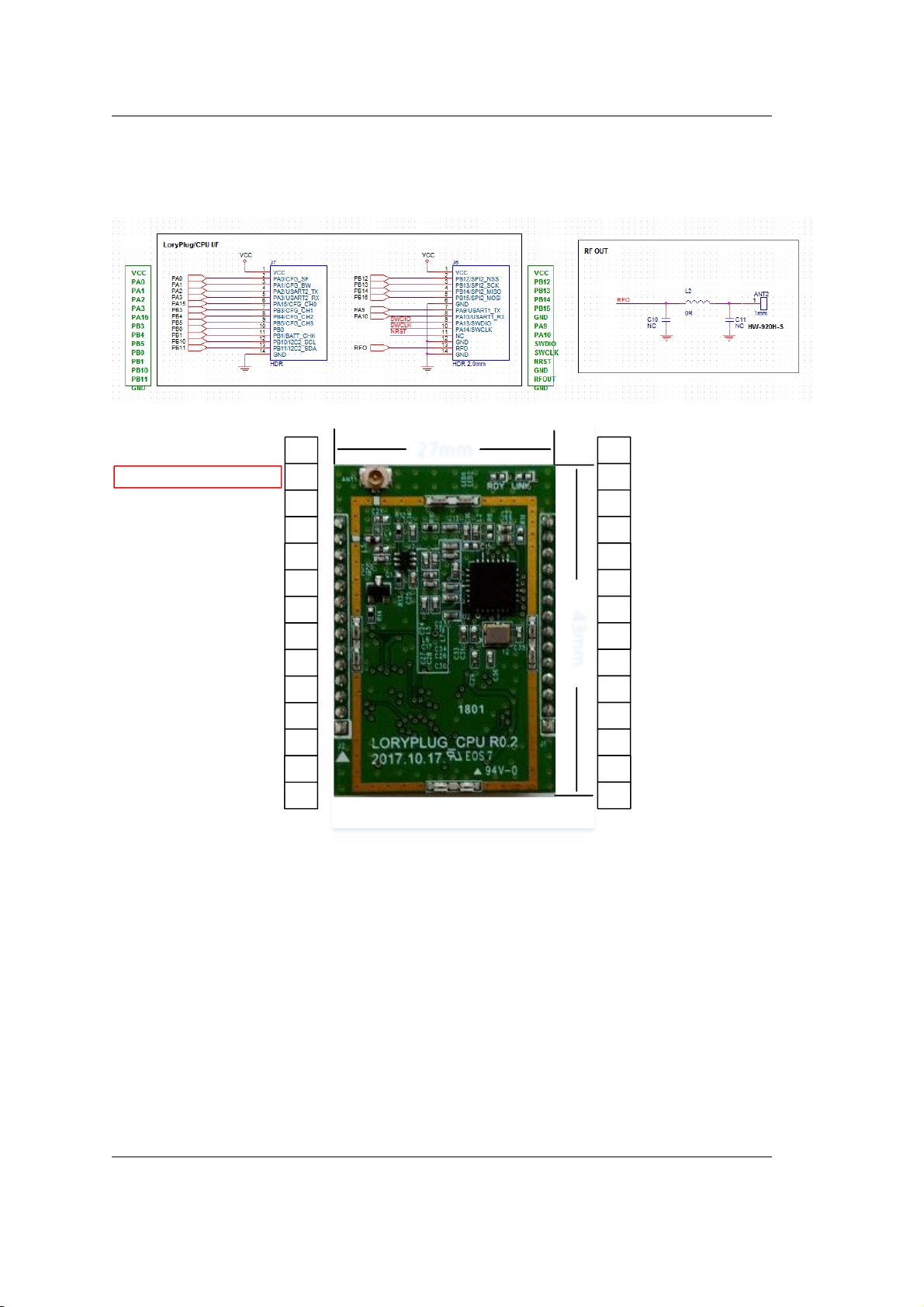
4.1 Specification
27mm
43mm
14
13
12
11
10
9
8
7
6
5
4
3
2
1
28
27
26
25
24
23
22
21
20
19
18
17
16
15
PB12 SPI2_NSS
VCC VCC
PB13 SPI2_SCK
PB14 SPI2_MISO
PB15 SPI2_MOSI
GND GND
PA9 UART1 Rx
PA10 UART1 Tx
SWDIO SWDIO
SWCLK SWCLK
NRST NC
GND GND
RF Out Extern
GND GND
GND GND
I2C2_SDA PB11
I2C2_SCL PB10
Battery PB1
PB0
DIP Switch PB5
DIP Switch PB4
DIP Switch PB3
DIP Switch PA15
UART2 Rx PA3
UART2 Tx PA2
DIP Switch PA1
DIP Switch PA0
VCC VCC

LoryPlug/CPU SDK
Manual
9
Category
Item
Specification
System
CPU
ARM CORTEX-M3
Wired
Interface
Port
UART*3, I2C*1, ADC*2, GPIO*6
Wireless
Interface
Frequency
Usable Frequency
917.3MHz, 917.9MHz, 918.5MHz, 919.1MHz,
919.7MHz, 920.3MHz, 920.7MHz, 920.9MHz,
921.1MHz, 921.3MHz, 921.5MHz, 921.7MHz,
921.9MHz, 922.1MHz, 922.3MHz. 922.5MHz,
922.7MHz, 922.9MHz. 923.1MHz, 923.3MHz
Display
LED
RDY, LINK
Power
Input
3.3V
Connector
B TO B
MOLEX SD-53748-002
Operating
Conditions
Temperature
-40℃ ~ +85℃ (-40℉ ~ +185℉)
Humidity
5~95% Non-Condensing
*Wireless certification has been obtained for the specifications listed in the above table. Do not use
wireless communication that are different from the above specifications.

LoryPlug/CPU SDK
Manual
10
4.2 Dimension
LoryPlug/CPU SDK
Manual
11
4.3 Recommended Antenna Circuit(Example)
27mm
43mm
14
13
12
11
10
9
8
7
6
5
4
3
2
1
28
27
26
25
24
23
22
21
20
19
18
17
16
15
PB12 SPI2_NSS
VCC VCC
PB13 SPI2_SCK
PB14 SPI2_MISO
PB15 SPI2_MOSI
GND GND
PA9 UART1 Rx
PA10 UART1 Tx
SWDIO SWDIO
SWCLK SWCLK
NRST NC
GND GND
RF Out Extern
GND GND
GND GND
I2C2_SDA PB11
I2C2_SCL PB10
Battery PB1
PB0
DIP Switch PB5
DIP Switch PB4
DIP Switch PB3
DIP Switch PA15
UART2 Rx PA3
UART2 Tx PA2
DIP Switch PA1
DIP Switch PA0
VCC VCC

LoryPlug/CPU SDK
Manual
12
Recommended Antenna Pattern
- Recommended Antenna: hanwooltech, HW-920H-S
Recommendation on matching circuit will be provided according to customer’s installation
conditions.
Sample base board example: Combine the module with the base board as shown in the image
below.
The antenna is soldered to the base board.
Module connector
Helical Antenna
Ground
RF Out
Grounding Pin
Grounding Pin
Helical Antenna
Sample Base Board

LoryPlug/CPU SDK
Manual
13
5. Connection Guide
This chapter describes the writing process and notes for user applications. The development and
testing of the LoryPlug/CPU used IAR compiler and ST-LINK/V2 Debugger of IAR SYSTEMS.
You can download the IAR compiler from the site below and use it for 30 days by authorizing a
free license. Other development environment related matters are as follows.
5.1 Development Environment
- Compiler : IAR 8.3 or above
- Free version
IAR Link:
https://www.iar.com/kr/iar-embedded-workbench2/#!?currentTab=free-trials
- Development Tool : ST-LINK/V2
- Development Language : C Language
- Development OS Environment : Windows10 64bit (Please refer IAR Site for other available OSs)
5.2 Folder Structure
The source and library folder structure provided by the LoryPlug/CPU SDK is as follows:

LoryPlug/CPU SDK
Manual
14
- Project: main folder of application program
- Library: MCU library provided by STM
- App : main source folder
- LoryNet: LoryNet protocol engine and library sources
- LoRa : LoRa communication port process source
- Sensor : temperature/humidity sensor process source
- Exe : folder where firmware is generated after compiling
- List : memory map information of compiled binary code
5.3 Source Contents
The contents of source files included in the App folder are as follows:
LoryPlug_SDK.eww : project environment file for IAR compiler
Main.c : startup program
Sb_struct.h : Config information and structure used by LoryNet and each process
Sb_defile.h : default value used by application process
Gpio_init.c : initialization settings for GPIO ports used by application process
I2c.c : I2C port settings (temperature/humidity sensor)
Spi.c : SPI port settings (Serial Flash)
Stm32l1xx_it.c : interrupt handler settings
LoryNet/Lorynet.c : LoryNet engine
LogNet/Sb_Library.c : APIs and libraries
Lora/Lora_Port.c : LoRa communication port process
Sensor/Th.c : temperature/humidity sensor process

LoryPlug/CPU SDK
Manual
15
5.4 Function Map
The application included in the LoryPlug/CPU SDK is based on the LoryNet and the structure of the
function is as follows:
The application provided is composed of three processes (device, LoRa, sensor) and with the
exception of device process, LoRa and sensor processes consists of four layers.
The area users write is primarily the App Layer, where you receive and process data from the other
party. Link Layer uses same LoRa and serial processes source which is the communication interface
provided by SystemBase, so there is nothing to modify. However, in case of temperature/humidity
sensor just as SDK, users can develop applications by modifying the data reading part in Link Layer
as it is a case of adding new sensors or devices.
Table Layer and Route Layer are table communication based LoryNet engine provided by
SystemBase, which correspond to layers 3,4 (TCP/IP) in OSI 7 layer and can be called and used
without modification.

LoryPlug/CPU SDK
Manual
16
API
Description
Main_Proc
- Initialize the settings used by the device itself on the first call.
- Call Table_Layer every 1 second to view and read packets received.
- The read packets are processed by App Layer, which is the user-writing area.
- Call the LoRa, Sensor port process that belongs to itself.
Lora_Proc
- Initialize the LoRa communication interface settings on the first call.
- Read packets from Link Layer to LoRa and raise them to higher Route Layer
or send them through the LoRa port if they have packets to send.
- Route_Layer places received LoRa packets in the destination table.
- Table_Layer analyzes packets that came to him and Read or Write its table
information.
-App_Layer detects and processes changes in its table information.
Sensor_Proc
- Initialize the Sensor interface settings on the first call.
- Regularly read sensor information from Link Layer and renew it to it’s table.
- Read packets from Link Layer to LoRa and raise them to higher Route Layer
or send them through the LoRa port if they have packets to send.
- Route_Layer places received LoRa packets in the destination table.
- Table_Layer analyzes packets that came to it and R/Ws its table information.
- App_Layer detects and processes changes in its table information.
Sleep_Mode
- Regularly enters Sleep Mode by the Scale/Interval time defined in the
sensing option of temperature/humidity sensor.
- Disconnects the power supply of all peripheral devices before entering the
Sleep Mode.
- The types of Sleep Modes are mainly Sleep and Standby type. Provided
example is Standby Mode, which is a super power-saving mode
disconnecting all powers other than RTC for battery use for three years.
- In Standby Mode, all power other than RTC is cut off, so when waking up
from sleep, it restarts from the beginning just as the power reset

LoryPlug/CPU SDK
Manual
17
Get_Config
- Read the operation setting information stored in Flash Memory within the
MCU.
Factory_Default
- As Flash does not have basic information during the first startup after
production, it is used to record the default values in Flash or resets to the
factory defaults by Reset Switch.

LoryPlug/CPU SDK
Manual
18
5.5 APIs
This chapter introduces the various APIs that users can use to program by using LoryPlug/CPU SDK.
Get_Main_Flash
Function
Reads data which is loaded into Flash Memory in STM CPU
Format
void Get_Main_Flash (uint32_t addr, uint8_t *Buff, int len)
Parameter
Addr
*Buff
Len
Absolute address of Flash Memory
Buffer address to be read and saved and
returned
Length to read
Returns
None
Notice
Write_Main_Flash
Function
Write data on Flash Memory in STM CPU
Format
void Write_Main_Flash (uint32_t addr, uint8_t *Buff, int len)
Parameter
Addr
*Buff
Len
Absolute address of Flash Memory
Buffer address
Length to save
Returns
None

LoryPlug/CPU SDK
Manual
19
Erase_Main_Flash
Function
Erases the sector before writing data on Flash Memory in STM
CPU
Format
void Erase_Main_Flash (uint32_t addr, int Sector_Ea)
Parameter
Addr
Sector_Ea
Absolute address of Flash Memory
Number of sectors to erase (Size of a sector is
1K Bytes)
Returns
None
Sleep_Mode
Function
Switch LoryPlug/CPU into Standby mode
Format
void Sleep_Mode ()
Parameter
None
Returns
None
Notice
Sleep mode provided by SDK supports Standby mode as
standard. Standby mode is a low power mode which stops all
functions except RTC. When waking up at the set time, all state
information before standby mode is cleared and runs again
from the beginning just as a power reset.
SB_Printf
Function
Output for debug, which is same as Printf provided by standard
C and outputted via Serial Port (Debug Port)
Format
void SB_Printf (char *Fmt, …)
Parameter
Fmt
Output format of standard Printf function
Returns
None
Notice
Same as the standard Printf and outputted via Serial Port
SB_msleep
Function
Makes process wait for the specified time
Format
void SB_msleep (unsigned int msec)

LoryPlug/CPU SDK
Manual
20
Parameter
msec
Time to wait (msec)
Returns
None
Notice

LoryPlug/CPU SDK
Manual
21
6. How to Use
The compiler compiles the application sources provided by the LogPlug/CPU and converts them
into binary files. This chapter provides example of the use of IAR Embedded Workbench IDE, the
most commonly used compiler, and assumes that users’ PC has an IAR compiler installed.
6.1 To RUN IAR Compiler
Run IAR IDE by double-clicking on "LoryPlug_SDK.ew" project file in the Project folder.
Select Rebuild All in the Project column or press Ctrl+F7 to compile the source.
If the compile results are correct, a binary file is created as "LoryPlug_CPU.bin" in the Firmware.exe
folder.

LoryPlug/CPU SDK
Manual
22
6.2 Operation Test
For operation test, you can check the operation status by connecting the debug port to PC. Run
the communication emulator program on your PC and set the serial settings to 115.2Kbps, Parity
None, 8 Bit Data, 1 Stop Bit.
The LogPlug/CPU operation test can be run by changing/compiling/uploading the Defined
Test_Mode value early in Main.c.
<Test Mode>
Value
Contents
0
Operates in LoryNet mode and regularly transmits temperature/humidity sensor
values via LoRa Network to the destination ID 0xfffffe LoryNet device. Depending
on the Sleep_ON/OFF option, transfers the sensor value at a one minute distance
set by default and repeats the process of entering Sleep mode.
1
The interface under test is on active state of Serial Flash, temperature/humidity
sensor, charge state, deep switch and Reset SW.
<Setup Mode>
You can enter setup mode if you need to change the default ID and initialize the settings.
Setup Mode remains waiting state for users’ Command request. If you set Test_Mode to 0, which
is called Operating Mode, the LogPlug/CPU remains all stop except the Timer to conserve battery
life, until it wakes up every 60 seconds. For this reason, firmware updates are not possible in Sleep
mode, so you can switch to Setup Mode to update the firmware.

LoryPlug/CPU SDK
Manual
23
To change your ID to No. 255, type:
myid=255 (Enter)
The ID of the LogPlug/CPU must be used within the range of 10000000 to 16000000.
To initialize the settings, type:
default (Enter)
Refer to Factory_CFG() function in main.c for initial values.
To turn on encryption function, type:
aes=1 (Enter)
The AES Key value is set to the Default value if you do not change it.
To change the AES Key value, type as below:
After entering AES Key 16 bytes, you must enter AESIV 16 bytes to change it successfully.

LoryPlug/CPU SDK
Manual
24
<Interface Test>
When Test_Mode is set to 1, the following operating status is outputted via Debug Port:
<LoryNet Operation >
When Test_Mode is set to 0, the following operating status is outputted via Debug Port:
Reads the sensor information and pass temperature/humidity information to destination 0xfffffe
at a certain interval.
 Loading...