

Systematics MP140 Owner's Manual
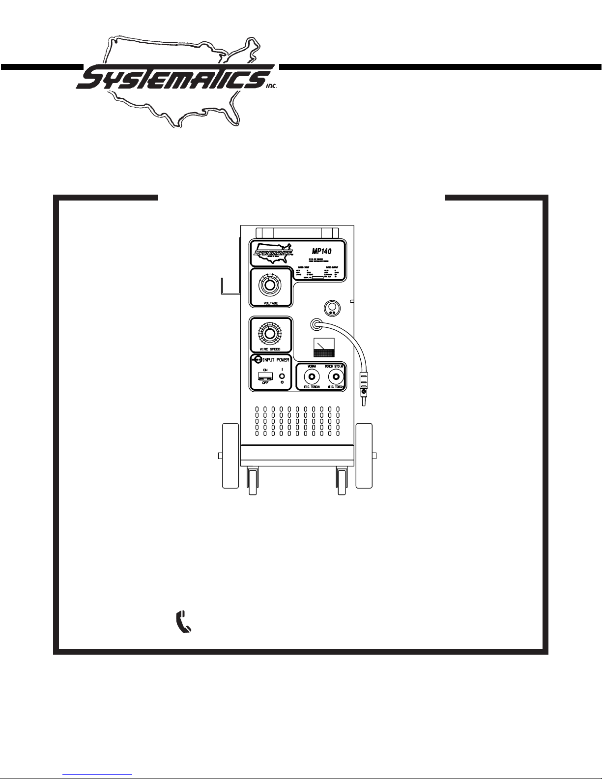
OWNER'S MANUAL
MP140 MIG COMBINATION UNIT
THE MP140
REPRESENTS THE LATEST TECHNOLOGY
IN MIG COMBINATION UNITS. THE MP140 OPERATES
ON 115 VOLT AC SINGLE PHASE CURRENT, AND FEATURES
"SMOOTH ARC" TRANSFORMER DESIGN CONCEPT.
FOR TECH. SERVICE, CALL 1-610-696-9040
FORM WC5342 Rev. 8/00
INSTALLATION
OPERATION
MAINTENANCE

MANUFACTURER’S LIMITED WARRANTY
!
WARNING
This equipment is warranted against defects in materials
and workmanship for a period of two years from the date of
purchase.
EXCEPTION: THE MIG TORCH IS WARRANTED FOR A
PERIOD OF 30 DAYS FROM THE DATE OF PURCHASE.
Should the equipment become defective for such reason,
the Manufacturer will repair it without charge, if it is returned
to the Manufacturer’s factory, freight prepaid. This warranty
does not cover: (1) failure due to normal wear and tear; (2)
consumable parts, such as, but not limited to, torch contact
tips, gas cups and insulating bushings; (3) damage by
accident, force majeure, improper use, neglect, unauthorized repair or alteration; (4) anyone other than the original
purchaser.
THIS LIMITED WARRANTY IS IN LIEU OF ALL OTHER
WARRANTIES, EXPRESS OR IMPLIED. THE MANUFACTURER SHALL NOT BE LIABLE FOR ANY INJURY TO
PERSONS, INCLUDING DEATH; OR LOSS OR DAMAGE
TO ANY PROPERTY, DIRECT OR CONSEQUENTIAL,
INCLUDING, BUT NOT LIMITED TO, LOSS OF USE,
ARISING OUT OF THE USE, OR THE INABILITY TO USE,
THE PRODUCT. THE USER ASSUMES ALL RISK AND
LIABILITY WHATSOEVER IN CONNECTION WITH THE
USE OF THE PRODUCT, AND BEFORE DOING SO,
SHALL DETERMINE ITS SUITABILITY FOR HIS INTENDED USE, AND SHALL ASCERTAIN THE PROPER
METHOD OF USING IT.
SOME STATES DO NOT ALLOW LIMITATIONS ON
HOW LONG AN IMPLIED WARRANTY LASTS, OR THE
EXCLUSIONS OR LIMITATIONS OF INCIDENTAL OR
CONSEQUENTIAL DAMAGES. SO THE ABOVE LIMITATIONS OR EXCLUSIONS MAY NOT APPLY TO YOU. THIS
WARRANTY GIVES YOU SPECIFIC LEGAL RIGHTS, AND
YOU MAY HAVE OTHER RIGHTS WHICH MAY VARY
FROM STATE TO STATE.
ARC WELDING CAN BE INJURIOUS TO OPERATOR AND PERSONS IN THE WORK AREA -——
CONSULT INSTRUCTION MANUAL BEFORE
OPERATING.
ELECTRIC SHOCK can kill.
• Do not touch electrodes or other electrically live parts.
• Insulate yourself from work and ground.
• Install and ground machine in accordance with the National
Electical Code and local code(s). Read Operating Manual
before installing or operating.
• Do not operate with protective covers, panels, or guard
removed.
• Disconnect input power before servicing.
• Only qualified personnel should install, use, or service this
equipment.
ARC RAYS can injure your eyes and burn
skin.
• Wear correct eye, ear, and body protection while welding.
FUMES AND GASES can be dangerous to your
health.
• Use enough ventilation and/or exhaust at the arc.
• Keep your head out of fumes.
• Do not breathe fumes.
READ AND UNDERSTAND THE
MANUFACTURER’S INSTRUCTIONS AND
YOUR EMPLOYER’S SAFETY PRACTICES.
See American National Standard Z49.1, “Safety in
Welding and Cutting”, published by the American
Welding Society, 2501 N.W. 7th St., Miami, Florida
33125; OSHA Safety and Health Standards, 29 CFR
1910 available from U.S. Dept. of Labor, Wash.,
D.C. 20210.
ELECTRICAL SUPPLY REQUIREMENTS................................... 1
INTRODUCTION ........................................................................... 2
SPECIFICATIONS......................................................................... 3
CHECK LIST (CONTENTS) .......................................................... 4
INSTALLATION ............................................................................. 4
OPERATION ................................................................................. 7
MAINTENANCE ........................................................................... 13
TROUBLE SHOOTING CHART.................................................. 15
CONNECTING TIGIT2 OR MHG7 SPOOL GUN ........................ 20
CONSUMABLE PARTS BREAKDOWN ..................................... 22
PARTS BREAKDOWN - MIG TORCH ........................................ 23
OPTIONS - TIGIT2, MHG7 SPOOL GUN ................................... 24
Systematics , Inc. 1025 Saunders Lane West Chester, PA. 19380
TABLE OF CONTENTS

ELECTRICAL SUPPLY REQUIREMENTS FOR THE MP140
Ensure that there is a 115 volt single phase, 20 amp electrical supply within easy reach
of the unit. The input cable supplied is 20 feet long. A 50 foot cable is an optional extra. The
plug which is factory installed is suitable for use up to 120 amps of output. The plug must
be changed if the welder is used above 120 amps of output. Attach a suitable plug
sure the green wire is attached to ground. Refer to boxes below with the WARNING and
NOTE headings for more information. All wiring should be performed by a qualified
electrician.
making
WARNING
To conform to the National Electrical Code, the power input plug must be
changed if this unit is to be operated on a 20 amp circuit or higher.
Never change fuses or circuit breakers to a higher value than the wires and
outlet are designed for.
Breaker size - Wire size
15 Amp 14 Gauge
20 Amp 12 Gauge
30 Amp 10 Gauge
Do not rely on the circuit breaker built into the MP140 to protect your wiring.
This circuit breaker protects the MP140 internal wiring only.
Do not use undersized extension cords. Follow the cord manufacturer's
recommendations as to current carrying capacities.
Make sure all electrical wiring is installed by a qualified electrician.
NOTE
The maximum output of the MP140 will be limited by the size (amp rating) of
the circuit used.
Operation on a 15 amp circuit (14 gauge wire) will limit maximum
output to 100 amps.
Operation on a 20 amp circuit (12 gauge wire) will limit maximum
output to 120 amps.
Operation on a 30 amp circuit (10 gauge wire) will result in maximum
output of 140 amps.
MP140 output will be limited also by low input voltage (less than 120 volts),
long input cords and use of extension cords.
Systematics , Inc. 1025 Saunders Lane West Chester, PA. 19380 1
INTRODUCTION
The Systematics MP140 is a com-
bination welding power source,
wire feed unit, MIG torch and
accessory package. It operates on
115 volts AC input current and is
designed to meet the requirements
of auto body repair shops and light
fabrication. The MP140 produces
fusion welds by the Gas Metal Arc
Welding process (GMAW or MIG), on
steel up to 1/4" thick(aluminum 3/
16") , using .023" through .045"
steel wire and 3/64" aluminum
wire(Optional liners and contact
tips must be purchased to cover
given wire sizes). Heavier sec-
tions can be easily welded using
slightly different techniques. Consumable MIG Spot/Stitch Welding on
steel can be performed with the
Optional SSTP-2 module installed.
The number of controls on the
unit have been reduced to assist
inexperienced operators learn MIG
welding. This facilitates rapid
set up for welding different thicknesses of material requiring various heat inputs. The VOLTAGE control adjusts the welding voltage
and the WIRE SPEED control adjusts
the speed of the wire drive motor.
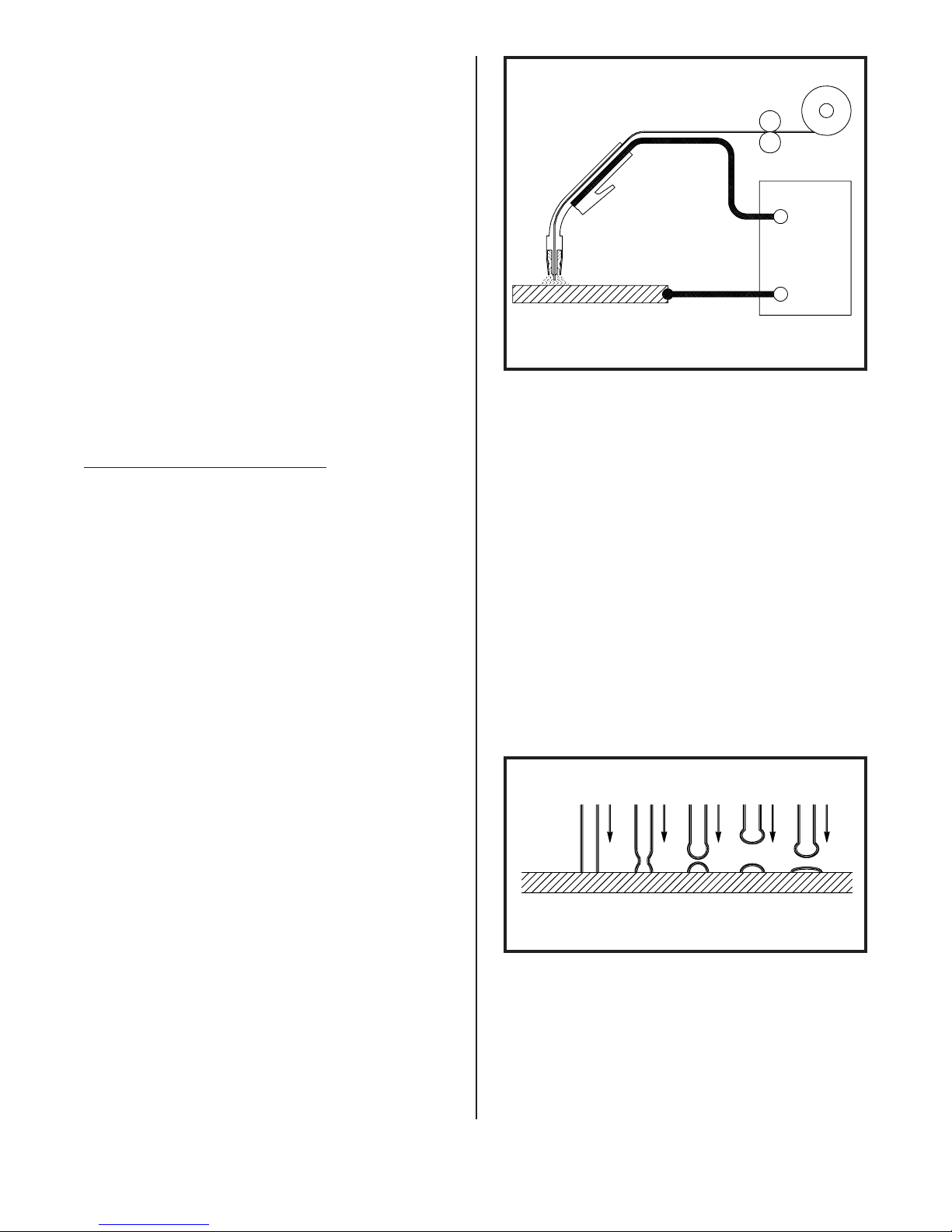
THE MIG PROCESS
AS APPLIED TO THE MP140
WIRE SPOOL
FEED
ROLLS
MIG
TORCH
POWER SOURCE
+
REVERSE
POLARITY
SHIELDING GAS
WORK
FIG. 1. SCHEMATIC OF MIG PROCESS
(STD.)
_
SHORT ARC OR DIP TRANSFER
Short arc transfer occurs at 12
to 22 arc volts (voltage while
welding), depending on wire size.
Welding commences as the arc is
struck and a weld pool is formed.
The tip of the electrode wire dips
into the pool and causes a short
circuit. The short circuit current
flow causes a rapid temperature
rise in the electrode wire and the
end of the wire is melted off. An
arc is immediately formed between
the tip of the wire and the weld
pool, maintaining the electrical
circuit and producing sufficient
heat to keep the weld pool fluid.
The electrode continues to feed and
again dips into the pool.
The MIG process uses a bare,
consumable electrode in the form of
spooled wire, which is fed by a
controllable speed feed unit through
the cable and torch to the weld. The
emerging wire and the weld are
shielded by a stream of CO2, Argon,
ELECTRODE
WORK
or a mixture of the two, which
prevents oxidation of the molten
weld puddle. The gas shield enables
high quality welds to be made
FIGURE 2. SHORT ARC TRANSFER
without the use of flux, eliminating the need for slag or flux
removal after the weld is completed.
This sequence of events is repeated up to 200 times per second.
Short arc transfer is suitable for
positional welding. The heat input
The consumable electrode wire is
melted and transferred to the weld
puddle by the "short arc" or "dip"
transfer mode.
to the workpiece is kept to a
minimum which limits distortion
and makes possible the welding of
thin sheet material.
2 Systematics , Inc. 1025 Saunders Lane West Chester, PA. 19380

DESCRIPTION
SPECIFICATIONS (Cont.)
The MP140 consists of a combina-
tion MIG welding power source and
wire feed unit, a MIG torch with 10
foot cable, a ten foot work (ground)
cable with ground clamp, a fifteen
foot power input cable, a gas
regulator/flowmeter, a torch accessory kit, and a built-in cylinder rack and industrial wheel kit.
Welder controls are simple and
clearly marked. The output voltage
is controlled by a six position tap
switch, providing six voltage selections. Voltages can be monitored by the voltmeter on the
control panel. Wire feed speed is
controlled by the wire speed potentiometer.
An OPTIONAL SPOT/STITCH WELD
(SSTP-2)control module with adjustable timer circuit provides
Consumable MIG Spot Welding or
Stitch Welding capabilities of
light gauge steel.
SPECIFICATIONS
PART NUMBER: MP140
INPUT POWER REQUIREMENTS:
Voltage 115 volts AC
Phase single phase
Frequency 50/60 hertz
Current (see OUTPUT POWER)
ARC VOLTAGE: 14 - 24 volts DC
WELD CURRENT RANGE:
30 - 140 amps
WIRE TYPES: mild steel,
stainless steel, aluminum,
bronze, flux cored, flux cored
gasless
WIRE SIZES: .023" - .045" steel,
3/64" aluminum,
(.023" - 3/64" alum. w/ Spool Gun)
.030" - .035" bronze,
.030" - .045" flux cored
(gas shielded or gasless)
WIRE FEED SPEED RANGE:
50 - 500 inches per minute
SHIELDING GASES:
For Steel Argon/CO2 mix or CO2
For Aluminum, Bronze Argon
For Stainless Steel
Argon + 2% Oxygen
For Flux cored Argon/CO2 mix or
CO2
DIMENSIONS:
Height 31 in.
Width 14-1/2 in.
Depth 35-1/2 in.
Weight 175 lbs.
TORCH SPECIFICATIONS
OUTPUT POWER @ 100% Duty Cycle:
15 Amps Input Current = 100 Amps
20 Amps Input Current = 120 Amps
OUTPUT POWER @ 60% Duty Cycle:
30 Amps Input Current = 140 Amps
DUTY CYCLE TIME PERIOD:
OPEN CIRCUIT VOLTAGE:
18 - 33 volts DC
Systematics , Inc. 1025 Saunders Lane West Chester, PA. 19380 3
10 minutes
NECK ANGLE: 60 degrees
LEAD LENGTH: 10 feet
OVERALL LENGTH: 10 feet
COOLING METHOD: gas (air)
RATING - 60% DUTY CYCLE:
With Argon/CO2 gas 200 amps
With CO2 gas 225 amps
CHECK LIST
SHIELDING GAS CONNECTIONS
THE SYSTEMATICS MP140 INCLUDES THE
FOLLOWING:
1- Combination Power Source/Wire
Feeder
1- Cylinder Rack/Industrial Wheel
Kit
1- 15TG10 MIG Torch with adjust-
able nozzle
1- 15 foot Power Input Cable with
Plug
1- 10 foot Work(Ground)Cable and
Clamp
1- MP250PK Parts Kit
1- GR-FM Gas Regulator/Flowmeter
1- Nozzle, 1/2 in. orifice (in-
stalled on MIG torch)
1- Contact Tip, for .030 in. wire
(installed on MIG torch)
1- ER70S-6-30-3, Sample Spool of
.030" Steel Wire
ITEMS REQUIRED FOR MIG WELDING
WHICH ARE NOT PROVIDED WITH THE
MP140
1. Full cover welding helmet with
proper colored lens (shade 9 to
11 depending on operator’s pref-
erence).
2. Proper shielding gas and cylin-
der.
1. Place a cylinder of the appropriate shielding gas in the
rack at the rear of the machine
and secure it with the chain
provided.
2. Rapidly open and close the
cylinder valve. This will purge
dust and foreign matter from
the valve.
CAUTION
Take care to point the
valve outlet away from
yourself or other people,
as escaping high pressure
gas may be dangerous.
3. Attach the gas regulator/flowmeter supplied with this unit,
to the cylinder valve using a
suitable wrench.
NOTE
If this unit is to be used
with 100% CO2 shielding
gas, an optional gas regulator coupler is required.
3. Leather welding gloves.
4. 115 volt single phase AC power.
INSTALLATION
POSITIONING THE UNIT
Locate the unit near the welding
area and position it so there is
adequate clearance all around for
ventilation and maintenance.
ELECTRICAL SUPPLY
Follow the Electrical Supply
Requirements on page 1.
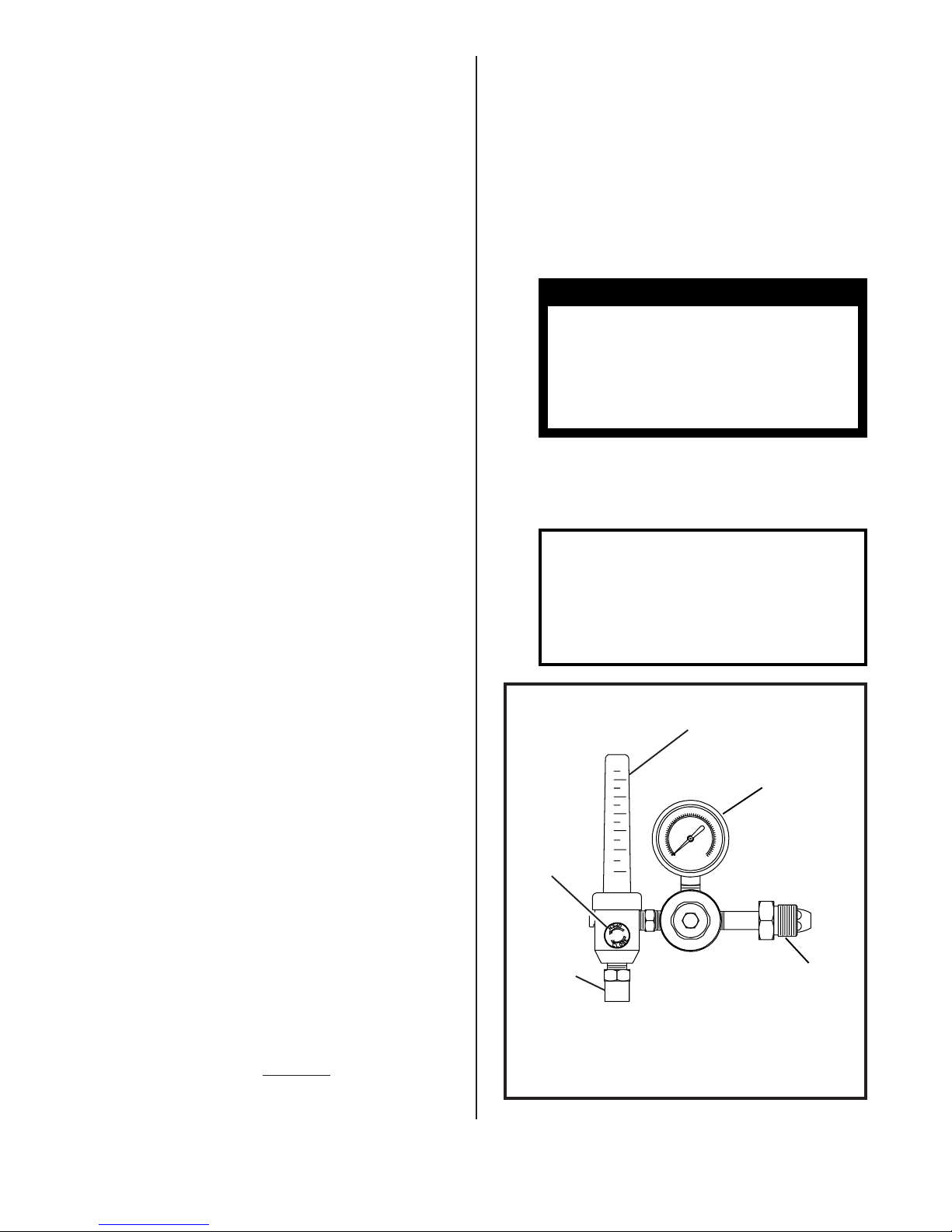
GAS FLOW
ADJUSTING
KNOB
OUTLET
FITTING
TO
WELDING
MACHINE
FIG. 3. GAS FLOW ADJUSTMENT
FLOW TUBE
INDICATES
FLOW RATE
IN C.F.H.
GAUGE -
INDICATES
TANK
PRESSURE
INLET
FITTING
TO
TANK
4 Systematics , Inc. 1025 Saunders Lane West Chester, PA. 19380
SHIELDING GAS CONNECTIONS(Cont.)
4. Fit the gas hose from the
welding machine to the regulator outlet fitting and tighten
it with a suitable wrench. Open
the cylinder valve.
5. Check that the gas regulator is
properly adjusted. When welding steel, the gas flow rate is
30 CFH. When welding aluminum,
the gas flow rate is 40 CFH.
NOTE
The MP140 must be turned
"ON" and the MIG torch
trigger depressed, before
the gas flow rate can be
adjusted.
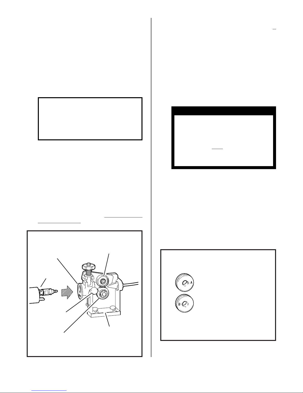
TORCH CONNECTION
FITTING AND THREADING THE ELECTRODE WIRE - ALWAYS USE ER70SWELDING WIRE
1. Remove the wire spool clip from
the spool hub.
2. Unpack the spool of welding
wire from its protective packaging.
3. Place the spool of ER70S-6
welding wire onto the hub. The
wire is fed off the bottom of
the spool.
CAUTION
Look for and remove any
wire protruding from the
center of the spool. The
protruding wire is electrically
ing and must not touch
the machine.
HOT during weld-
6
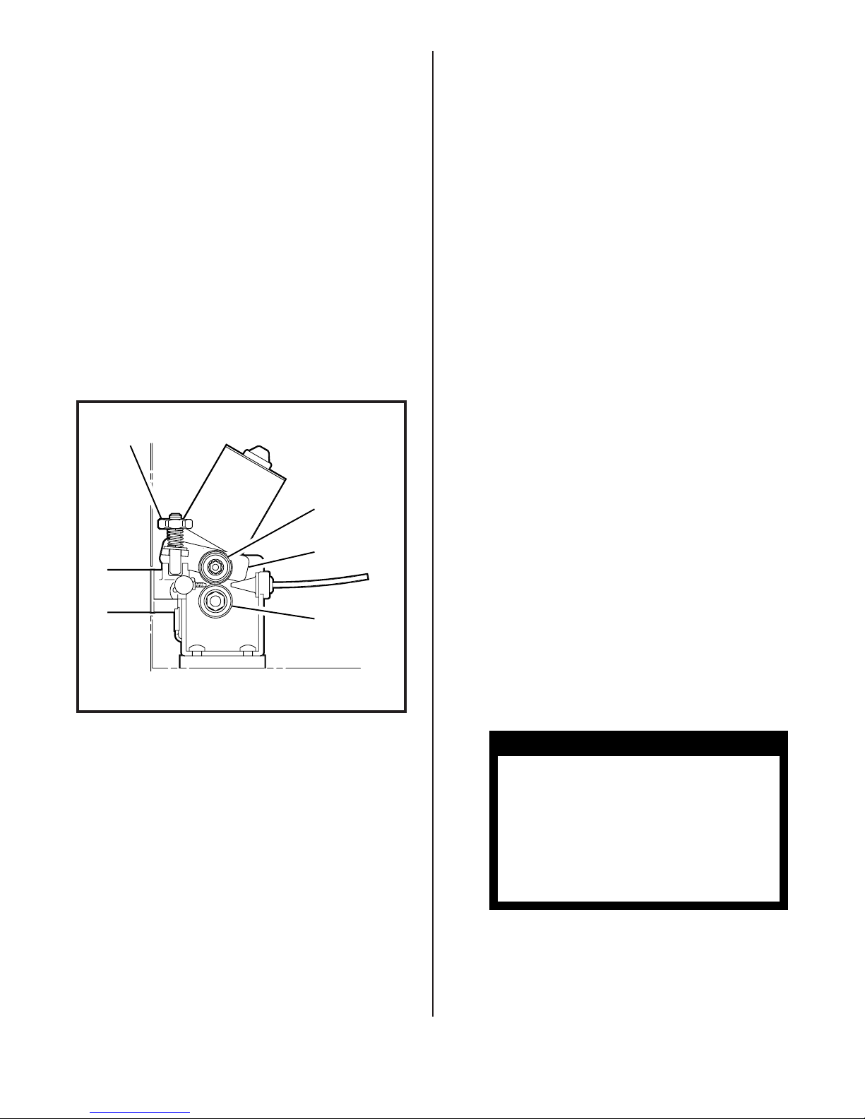
1. Open the access door of the
machine to its fullest extent.
2. Back out the thumb screw located on the drive assembly
mounting bracket inside the
machine. Insert the MIG torch
into the torch panel mount on
the front panel and TIGHTEN THE
THUMB SCREW.
TORCH PRESSURE
PANEL ROLL
MOUNT
MIG
TORCH
THUMB
SCREW
4. Replace the spool clip on the
hub.
5. Unlatch the pressure roll arm
and swing it open.
6. Make sure the double v-groove
drive roll is installed to
match the wire size. To change
the wire size setting, remove
the drive roll, turn it over and
reinstall it on the shaft.
"A" SIDE FACING IN FOR
.023" - .035" STEEL WIRES
"B" SIDE FACING IN FOR
.040" - .045" STEEL WIRES
AND 3/64" ALUMINUM WIRES
DRIVE DRIVE
ROLL ASSEMBLY
FIGURE 4. TORCH CONNECTION
Systematics , Inc. 1025 Saunders Lane West Chester, PA. 19380 5
FIG. 5. DOUBLE GROOVE DRIVE ROLL
(continued on following page)

FITTING AND THREADING THE ELECTRODE WIRE (Continued)
FITTING AND THREADING THE ELECTRODE WIRE (Continued)
7. Release the wire from the spool
and trim off the kinked end with
wire cutters. The wire must be
straight when it enters the
inlet guide.
8. Thread the electrode wire through
the inlet guide, over the feed
roll and into the torch liner.
Ensure that the wire locates in
the feed roll groove. Do not
allow the wire on the spool to
loosen.
9. Close and relatch the pressure
roll arm.
10.Stretch the torch cable straight
out in front of the machine
making sure there are no kinks.
Remove the nozzle and contact
tip from the torch.
11.Turn "ON" the circuit breaker on
the front of the machine. The
cooling fan will start and the
"ON" indicator light will illuminate. Set the VOLTAGE control
switch to "4", the function
switch to "CONTINUOUS WELD" (if
the unit has the optional SSTP2 installed) and the WIRE SPEED
control to "7". Pull the
trigger on the MIG torch. The
wire feed system will start and
wire will be fed through the
cable liner and torch. If the
wire does not feed, or appears
to slip, tighten the pressure
roll arm adjusting nut. Feed
the wire until it protrudes
from the front of the torch
approximately six inches.
CAUTION
12.Install the contact tip over the
protruding wire and tighten it
firmly using a proper size
wrench. Make sure the tip is the
correct size for the wire being
used.
13.Install the nozzle on the torch.
For steel, the contact tip
should be flush or stick out up
to 1/16 inch beyond the end of
the nozzle. For aluminum, the
contact tip should be recessed
1/8 to 1/4 inch inside the
nozzle. Using wire cutters,
trim off the wire so the stickout
is approximately 1/4 inch for
steel or 1 inch for aluminum.
For aluminum, the end of the
wire should be bent over so it
does not JAM into the work. This
is called a "scratch start".
1/4"
STICK-
OUT
FOR STEEL:
CONTACT TIP
FLUSH WITH NOZZLE
FIGURE 6.
WIRE STICKOUT - STEEL, ALUMINUM
1"
STICK-OUT
FOR ALUMINUM:
CONTACT TIP
RECESSED 1/8" - 3/8"
Keep hands and face away
from the front of the
torch and do not allow the
wire to contact ground.
The wire is electrically
HOT when the torch trigger
is actuated.
6 Systematics , Inc. 1025 Saunders Lane West Chester, PA. 19380
14.For steel welding only, spray
anti-spatter compound inside
the nozzle and on the outside of
the contact tip. For aluminum
or stainless steel welding, NO
anti-spatter compound can be
used as it will contaminate the
weld.
WIRE FEED PRESSURE ROLL ADJUSTMENT
The wire feed pressure roll is
adjusted to the proper setting at
the factory, prior to delivery. It
may be necessary to readjust the
setting as components "seat in" or
when changing to a different diameter wire. To check for proper roll
pressure, hold the torch in one
hand and the wire between two
fingers of the other hand. Pull the
torch trigger. If the wire continues to feed when firm pressure is
applied to the wire, the pressure
roll adjusting nut should be backed
off until the feed rolls start to
slip. If the wire will not feed
with very little pressure applied,
the pressure roll adjusting nut
should be tightened.
PRESSURE ROLL
ADJUSTING NUT
PRESSURE
ROLL
PRESSURE
ROLL ARM
DRIVE
ROLL
FIGURE 7.
PRESSURE ROLL ADJUSTMENT
OPERATION
The following operating instructions and detailed setup procedures enable an operator without
previous experience to produce
quality fusion welds. It is recommended that an operator without
prior experience with this equipment, first practice on scrap metal
of the same type and thickness as
the material to be welded.
OPERATING SEQUENCE
1. Make sure that the pieces of
metal to be welded are free of
grease, dirt, paint and scale.
Use a wire brush to remove paint
and scale. Paint must be completely removed to bare metal.
Grease and oil could burn and
cause a fire or safety hazard.
Failure to clean the metal
properly will result in erratic
and porous welds.
2. Install the unit as directed in
the installation instructions
and make sure the work clamp is
firmly attached to a cleaned
area on the workpiece to be
welded.
3. Open the shielding gas cylinder
valve. Press the torch trigger
and listen for gas flow. Adjust
the gas flow rate to 30 CFH for
steel and 40 CFH for aluminum.
TORCH SELECTOR CABLE
Plug the torch selector cable
into the Positive (+) terminal on
the machine(see "Process Selec-
tion" on page 8 for further details).
WORK (GROUND) CABLE
Uncoil the work cable and plug it
into the negative (-) terminal on
the machine.
Systematics , Inc. 1025 Saunders Lane West Chester, PA. 19380 7
CAUTION
The welding wire will feed
when the trigger is actuated. Take care that the
wire is not directed to
hit yourself or anything
that is grounded to the
ground wire on the welder.
 Loading...