

Page 1
Z-Wave to Systemair HVAC Adapter
GB User Manual
Document in original language | A002
Page 2

© Copyright Systemair UAB
All rights reserved
E&OE
Systemair UAB reserves the rights to alter their products without notice.
This also applies to products already ordered, as long as it does not affect previously agreed specifications.
| A002
Page 3

1 Declaration of Conformity ....... .... .... .... . .... .... .... .1
2 Overview . ..... ... . .... .... .... .... .... .... . ... . .... .... .... ...2
3 Z-Wave coexistence ... .... .... .... . .... .... .... .... .... .... 2
4 Installation.. .... .... .... ..... ... . .... .... .... .... .... .... . ... . .2
5 Settings menu ..... . .... .... .... .... .... .... .... . .... .... .... .3
6 Add device to Z-Wave network —
Inclusion.... .... .... . ... . .... .... .... .... .... .... .... . .... .... ..3
7 Remove device from Z-Wave network —
Exclusion .... .... .... .... .... . ... . .... .... .... .... .... .... . ... . .3
8 Associations. .... .... .... . ... . .... .... .... .... .... .... . ... . .... 3
9 Thermostat HVAC and Basic command
class. .... . ... . .... .... .... .... .... .... . ... . .... .... .... .... .... ..3
10 Application status .... .... .... .... .... . ... . .... .... .... .... ...4
11 Temperature setpoint. . .... .... .... .... .... .... . ... . .... .... 4
12 Fan mode .... .... .... . ... . .... .... .... .... .... .... . ... . .... .... 4
13 Boost Mode .. .... .... .... .... .... .... .... . .... .... .... .... .... 4
14 Alarms... .... .... .... . .... .... .... .... .... .... .... . .... .... .... .4
15 Configuration .. .... . .... .... .... .... .... .... .... . .... .... .... .5
16 Operational modes and indicators . ... . .... .... .... .... ..6
16.1 Factory reset .... . ... . .... .... .... .... .... .... .... . ...7
16.2 Firmware uploading ... .... . .... .... .... .... .... .... 7
17 Configuring the unit while device is added to
Z-Wave network . . .... .... .... .... .... .... . ... . .... .... .... ..8
18 Technical specification... .... .... .... .... . ... . .... .... .... ..8
Contents
| A002
Page 4

Page 5

1 Declaration of Conformity
MMaannuuffaaccttuurreerr
Systemair UAB
Linų st. 101
LT–20174 Ukmergė, LITHUANIA
Office: +370 340 60165 Fax: +370 340 60166
www.systemair.com
hheerreebbyy ccoonnffiirrmmss tthhaatt tthhee ffoolllloowwiinngg pprroodduucctt
Z-Wave to Systemair HVAC Adapter
ccoommpplliieess wwiitthh aallll aapppplliiccaabbllee rreeqquuiirreemmeennttss iinn tthhee ffoolllloowwiinngg ddiirreeccttiivvee
• The Radio and Terminal Communications (R&TTE) Directive 1999/5/EC
aanndd tthhee ffoolllloowwiinngg hhaarrmmoonniizzeedd ssttaannddaarrddss aarree aapppplliieedd iinn aapppplliiccaabbllee ppaarrttss::
Declaration of Conformity |
1
EN 301-489-1 V1.9.2:2011
EN 301-489-3 V1.6.1:2013
EN 300 220-1 V2.3.1:2012
EN 300 220-2 V2.4.1:2012
EN 62479:2010
EN 60730-1: 2007:
Electromagnetic compatibility and Radio spectrum Matters (ERM); ElectroMagnetic
Compatibility (EMC) standard for radio equipment and services; Part 1: Common
technical requirements
Electromagnetic compatibility and Radio spectrum Matters (ERM); ElectroMagnetic
Compatibility (EMC) standard for radio equipment and services; Part 3: Specific
conditions for Short-Range Devices (SRD) operating on frequencies between 9 kHz
and 246 GHz
Electromagnetic compatibility and Radio spectrum Matters (ERM); Short Range
Devices (SRD); Radio equipment to be used in the 25 MHz to 1 000 MHz frequency
range with power levels ranging up to 500 mW; Part 1: Technical characteristics
and test methods
Electromagnetic compatibility and Radio spectrum Matters (ERM); Short Range
Devices (SRD); Radio equipment to be used in the 25 MHz to 1 000 MHz frequency
range with power levels ranging up to 500 mW; Part 2: Harmonized EN covering
essential requirements under article 3.2 of the R&TTE Directive
Assessment of the compliance of low power electronic and electrical equipment
with the basic restrictions related to human exposure to electromagnetic fields (10
MHz to 300 GHz)
Automatic electrical controls for household and similar use - Part 1: General
requirements
The units will meet the requirements of the WEEE and ROHS directives.
The complete technical documentation is available.
Skinnskatteberg, 05-05-2016
Mats Sándor
Technical Director
| A002
Page 6

Overview
|
2
2 Overview
The Systemair Z-Wave Ventilation is a residential heat recovery ventilation system, which consists of the following
main modules:
• Ventilation Unit, which is controlled by a module called PCU-ECx, where ‘x’ is a digit representing the module
generation
• One or more local User Interface/s called CDx, where ‘x’ is a digit representing the module generation. The CDx is
connected to the PCU-ECx. Via CDx the user can control locally the Ventilation Unit.
• Z-Wave to Systemair HVAC Interface Adapter, which connects the Z-Wave network with the Ventilation Unit.
3 Z-Wave coexistence
This Product can be included and operated in any Z-Wave network with other Z-Wave certified devices from other
manufacturers and/or other applications. All non-battery operated nodes within the network will act as repeaters regardless of vendor to increase reliability of the network.
4 Installation
Danger
• All electrical connections must be carried out by an authorized installer and in accordance with local rules
and regulations.
Z-Wave adapter connects a wireless control (gateway) and a residential unit to be able to communicate wireless.
11 Install the residential unit. Remove label that covers a
Modbus connection.
22 Connect Z-Wave adapter to the Modbus connection on
the unit using a provided cable with RJ45 type plugs.
33 Connect the Z-Wave adapter to the power supply.
| A002
Page 7
44 Activate and configure the gateway.
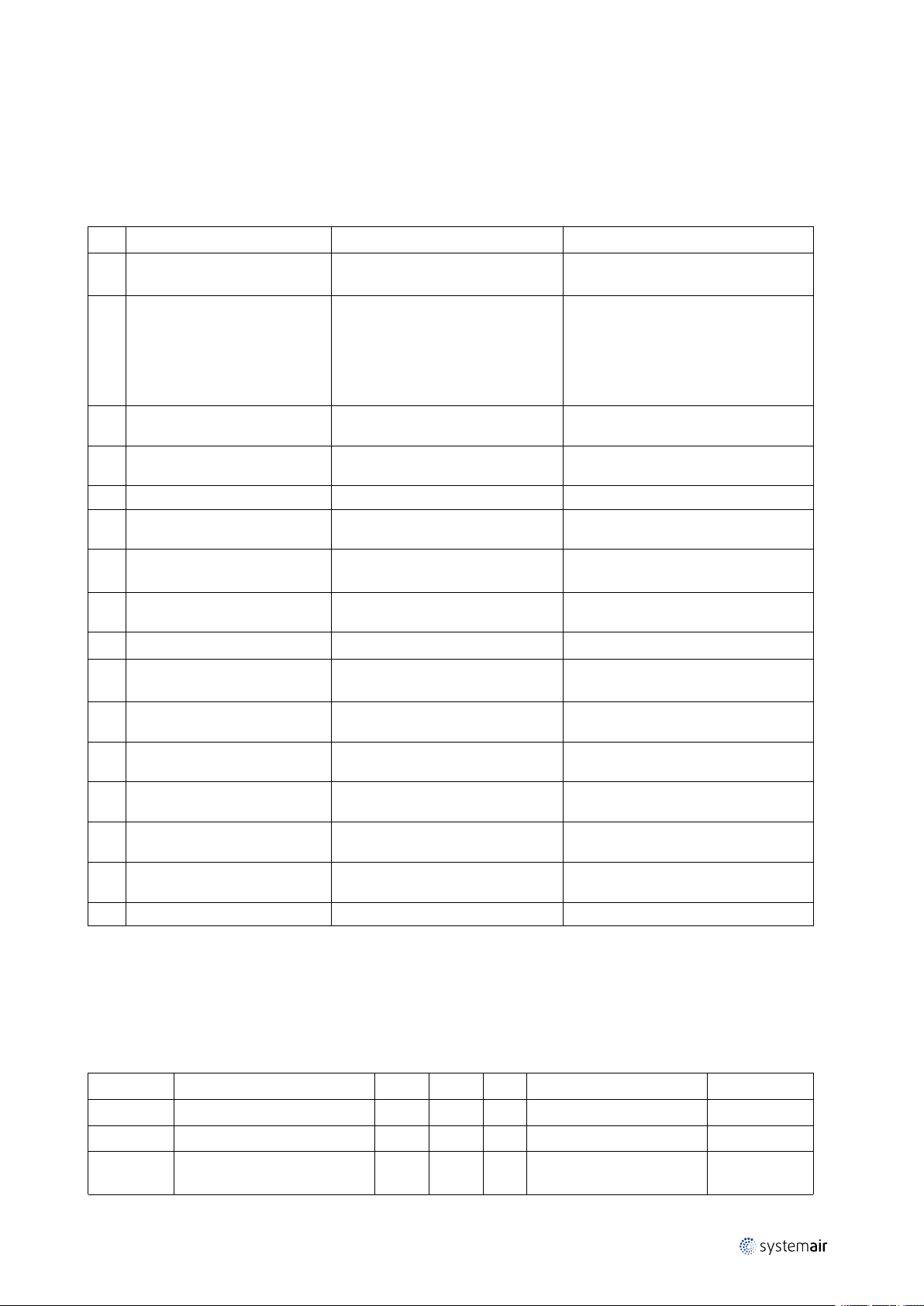
5 Settings menu
The following HVAC unit setting are relevant to Z-Wave interface adapter.
MMeennuu lleevveell 11 MMeennuu lleevveell 22 MMeennuu lleevveell 33 MMeennuu lleevveell 44
Service
Function
Language
→ Version
Service
Language
Version
→ Firmware
Service
Week program
Airflow log
→ Functions
1
Version [Unit type]
CD
Appl.
Boot.
Firmware
Unit
Gateway
Update
Function
Wireless
Defrosting
→ Modbus
5.05.00
1.00.02
CD
5.05.00
5.05.00
Yes/No
EC
5.07.00
2.00.06
EC
5.07.00
5.07.00
Modbus
→ Settings
Gateway
Modbus
Settings
→ Gateway
Settings
Address 1
Baud 19200
Parity None
Gateway
State:Not present/
Present/
Updating
Settings menu
|
3
1. White background on “Firmware” if no communication to gateway.
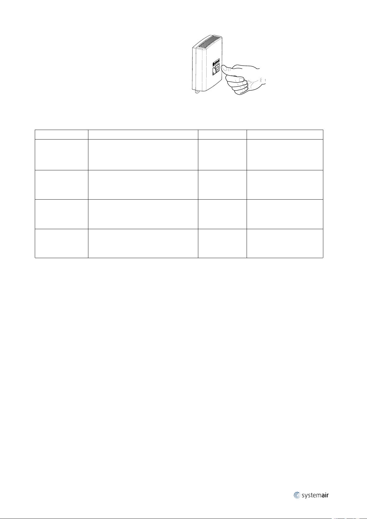
6 Add device to Z-Wave network — Inclusion
When the device is not added to a Z-Wave network, then triple short clicks of the inclusion button will start the inclusion. The device begins a classic inclusion. If after 3 attempts the inclusion doesn’t succeed, then the Network Wide Inclusion will be started.
7 Remove device from Z-Wave network — Exclusion
When the device is already included in a Z-Wave network, then triple short clicks of the inclusion button will exclude it
from that Z-Wave network.
8 Associations
The Device supports one, the Lifeline Association Group only. Maximum 5 nodes can be added to that group. The device
uses the Lifeline group to send the following unsolicited reports:
• Thermostat Mode Report – when thermostat mode changes,
• Thermostat Setpoint Report – when the temperature setpoint changes,
• Thermostat Fan Mode Report – when the fan level changes,
• Notification Report – when an alarm occurs,
• Switch Binary Report – when the device enter/exit the Boost mode,
• Device Reset Locally – at factory reset
9 Thermostat HVAC and Basic command class
The Systemair Z-Wave Ventilation supports two thermostat modes which are mapped to the Comfort and Energy Saving Mode:
| A002
Page 8

| Application status
4
Table 1 Thermostat HVAC Modes mapping
Thermostat Mode Command Class
Number Mode
0x0A
0x0D
Auto changeover
Away
Basic CC Set/Report Value Mapped as
0xFF
0x00
Comfort Mode
Energy Saving Mode
10 Application status
Some of the implemented CCs need to be translated to the Ventilation Unit via the Modbus interface. Due to some reasons that communication couldn’t be available, for example – disconnected/damaged communication cable. In order to
cover such situations, the Application Status Command Class has been implemented.
So, In case of no communication between Z-Wave Adapter and the Ventilation Unit Module, the Device will send “Application Reject Request” for all Z-Wave commands required communication with the Ventilation Unit.
If the Modbus communication is up and running, the device is always available to respond in the specified time, i.e. the
device will never report “Application Busy” command.
11 Temperature setpoint
The device supports “Thermostat Auto changeover” setpoint type only. The setpoint range varies in depend of the ventilation system type (Table 3) and some other ventilation unit configurations. All of these dependencies must be fixed
at inclusion time, so the system will be fully defined. The Host shall retrieve the setpoint range using the Thermostat
Setpoint Capabilities Get V3 command. In additional to the reported Min and Max Values, 0°C is supported as well.
The device accepts the setpoints in a predefined step in the reported range. It is available via the Configuration CC, parameter 5 (see Table 2: Configuration Parameters).
12 Fan mode
The device will support Fan Auto Mode, if both RH and CO2senors are present. This must be done at inclusion time.
The Z-Wave Systemair Ventilation supports following Thermostat Fan Modes:
Thermostat Fan Mode Ventilation Unit Fan
Bit Off Value Mode Mode Level
0 0
1
0 1 Low Low
0 3
0 5
Auto/Auto Low Demand/Automatic
- -
High High
Medium Normal
Manual
Auto
Off
13 Boost Mode
The Systemair Z-Wave Ventilation has implemented a Boost Mode. That mode overrides the selected fan speed, setting
it to a predefined level (usually high) for a predefined time period.
To set the Boost Mode remotely via Z-Wave, the Binary Switch CC is used. But that binary switch is a bit special – Once
it is turned ON, it locks itself in ON position for the predefined time period, and it can’t be turned off until that time period expires.
The Host can use the Ventilation System Boost mode in case of smoke or fire alarm for example.
14 Alarms
The implemented Notification CC V3 is used to report the device malfunctions:
• Notification Type 0x09 – “System”
• Event Type 0x03 – “System Hardware Failure with manufacture proprietary code”
The failures are reported in a two bytes value, where each bit represents a certain alarm. If the bit is set (1) the alarm is
active, and if the bit is cleared (0) the alarm is not active.
| A002
Page 9
Configuration |
Any bit’s transition from 0 to 1 will trigger an unsolicited Notification Report. The system maintains a repeat timeout
counter for each alarm, which is hard coded to 24 hours. So, an alarm occurrence runs its counter. When the repeat time
expires and the alarm still exists (its bit is set) a new unsolicited Notification Report will be send. A bit’s transition from
1 to 0 clears its repeat counter.
The alarms are generated in the Ventilation Unit.
Table 2 System Hardware Alarms/Failures
5
BBiitt
0 0x0001
1 0x0002
2 0x0004
3 0x0008
4 0x0010
5 0x0020
6 0x0040
7 0x0080 Low SS
8 0x0100
9 0x0200 RH Sensor
10 0x0400
11 0x0800
12 0x1000
13 0x2000
14 0x4000
15 0x8000
MMaasskk
Filter Alarm
Fan Alarm
Rotor Alarm
Frost Alarm
PB Failure Active when a load fault is detected.
Emergency Thermostat
Damper
Defrosting Active when defrosting has failed.
Supply Air Temperature Sensor
Extract Air Temperature Sensor
Exhaust Air/Preheater Temperature
Sensor
Over Temperature/Frost Protection
Sensor
Outdoor Air Temperature Sensor
Reserved
AAllaarrmm//FFaaiilluurree
DDeessccrriippttiioonn
Active when the time for filter
replacement has run out.
Active when no tacho signals have
been received for 20 seconds while
the fan shall be running. Cleared only
upon detection of tacho signals. So,
turning off the fans will not clear the
alarm flag.
Active in case no rotor signal is
received.
Active when the temperature
conditions for Frost alarm are valid.
Active when the emergency
thermostat is active.
Active in case of a failed damper test.
Can only be cleared by a power cycle.
Active if the supply sir temperature is
too low.
Active if the RH sensor is not detected
while it is required.
Active if the temperature sensor is
broken
Active if the temperature sensor is
broken
Active if the temperature sensor is
broken
Active if the temperature sensor is
broken
Active if the temperature sensor is
broken
15 Configuration
The device supports 7 configuration parameters. Some of them are read/write, but some are read only. All Configuration Set commands received for read only parameters will be ignored, i.e. the set command will not affect these
parameters.
Table 3 Configuration Parameters
## NNaammee
1 System Type
2
3
| A002
Filter - Period
Filter - Days Used
RR//WW
R 2
R 2
R 2
SSiizzee
DDeeff
- Ventilation System Type Table 3.
- In step of 30 days 6=180days
-
DDeessccrriippttiioonn
How many days has been
used since the last change
EExxaammppllee
Page 10

| Operational modes and indicators
6
Configuration Parameters cont'd
## NNaammee
4
5
6 CDx New Firmware Version
7
Table 4 Ventilation System Types for Parameter #1
NNuummbbeerr VVeennttiillaattiioonn SSyysstteemm TTyyppee
0 VR400
1 VR700
2 VR700DK
3 VR400DE
4 VTC300
5 VTC700
6 ÷ 11
12 VTR250
13 VTR200B
14 VSR300
15 VSR500
16 VSR150
17 VTR300
18 VTR500
19 VSR300DE
20 VTC200
21 VSC100
Boost Mode Remaining Time
Temperature Setpoint Step
Available
PCU-ECx New Firmware
Version Available
Not Used
RR//WW
R/W
R/W
SSiizzee
R 2
R 2
DDeeff
4 0
4 0
DDeessccrriippttiioonn
How many seconds are
left for Boost mode
The min change available
in degree Celsius x 10
The New FW Version:
MSB – don’t care/0x00,
Next – version High,
Next – version Middle,
LSB – version Low.
EExxaammppllee
25 = 2.5°C
V. 5.02.03:
MSB = x,
Next = 05,
Next = 02,
LSB = 03.
Parameters 6 and 7 are used to inform the user that a new firmware is downloaded in the Z-wave Adapter and is available for bootloading. Then the user can initiate the bootloading via the local UI (CDx).
16 Operational modes and indicators
The Z-Wave Adapter module has 4 operational modes:
• Normal
• Not Included
• Factory Reset
• Firmware Uploading
All operational modes and readiness to enter in a mode are indicated with a two colors LED.
The Z-Wave Adapter operates in Normal mode when it is included in a Z-Wave network and the communication with
the ventilation unit is up and running. That mode is indicated with the following LED pattern (OOnnee ssqquuiirree iiss aabboouutt 00..11ss,,
RR —— RReedd LLEEDD iiss OONN,, GG —— GGrreeeenn LLEEDD iiss OONN,, EEmmppttyy —— BBootthh aarree OOFFFF):
LLEEDD ppaatttteerrnn 11:: NNoorrmmaall mmooddee
G
| A002
Page 11

Operational modes and indicators |
While the Z-Wave Adapter is in Normal mode and in case of no communication with the Ventilation Unit, a Fault condition occurs and will be indicated as:
LLEEDD ppaatttteerrnn 22:: FFaauulltt ccoonnddiittiioonn iinn NNoorrmmaall mmooddee
R
While the device is not included in a Z-Wave network following led pattern is shown:
LLEEDD ppaatttteerrnn 33:: DDeevviiccee iiss nnoott iinncclluuddeedd
G R
16.1 Factory reset
Please, DO NOT use factory reset if the primary controller is present and operational, but remove device from Z-Wave
network instead. It is allowed to do factory reset if the primary controller is missing or inoperable only.
To do a Factory Reset the user must follow the following procedure:
1. Press and hold the inclusion button for 6 seconds – Device Indicate “Ready for Factory Reset”
LLEEDD ppaatttteerrnn 44:: FFaaccttoorryy rreesseett iiss rreeaaddyy
G G R R
7
2. Release it – Device Indicate “Factory Reset request accepted”
LLEEDD ppaatttteerrnn 55:: FFaaccttoorryy rreesseett rreeqquueesstt aacccceepptteedd
G G R R G G R R
3. Press it again and hold for 3 seconds – Indicate “Performing Factory Reset”
LLEEDD ppaatttteerrnn 66:: FFaaccttoorryy rreesseett mmooddee
G G R R
The Z-Wave Adapter is indicating each phase with a different LED pattern – see “Operational modes and indicators”.
At each step the Z-Wave Adapter will wait for a while for the next user action, and then will cancel the Factory Reset
procedure.
During the Factory Reset the device will resets all Z-Wave part. This includes parameter 6 and 7 values as well as the
eventually already downloaded (fully or partially) firmware images for ventilation unit.
After Factory Reset, the Z-Wave Adapter will enter in “Not Included” mode.
16.2 Firmware uploading
When the Z-Wave Adapter has been downloaded a new firmware version for PCU-ECx and/or CDx module/s, it/they
can be uploaded to the Ventilation Unit.
A Firmware Uploading is initiated by a request from the ventilation unit via its local UI. This will start the uploading of
the firmware available in the Z-Wave Adapter to the Ventilation Unit. The led pattern below shows the Firmware Uploading mode is about to be entered:
LLEEDD ppaatttteerrnn 77:: FFiirrmmwwaarree uuppllooaaddiinngg mmooddee rreeaaddyy
G G G R G G
Upon data transmission starting and acknowledged by the ventilation unit, the following ‘heart beat’ pattern is shown:
LLEEDD ppaatttteerrnn 88:: FFiirrmmwwaarree uuppllooaaddiinngg mmooddee ‘‘HHeeaarrtt bbeeaatt’’
G
G
| A002
Page 12

| Configuring the unit while device is added to Z-Wave network
8
Once the last page of the ventilation system is transmitted and confirmed, the following pattern will be shown:
LLEEDD ppaatttteerrnn 99:: FFiirrmmwwaarree uuppllooaaddiinngg ddoonnee
G G G G
A Fault condition during data transfer in Firmware Uploading mode will be indicated as:
LLEEDD ppaatttteerrnn 1100:: FFaauulltt ccoonnddiittiioonn iinn FFiirrmmwwaarree uuppllooaaddiinngg mmooddee
R R
The fault condition is terminated when the ventilation unit responses are detected again.
Please Note: To bootload the just uploaded firmware, the Ventilation Unit requires a power cycle.
17 Configuring the unit while device is added to Z-Wave network
It is not allowed to change any of these settings while the device is included in Z-Wave network:
• System type
• Heater type
2
• CO
and RH (relative humidity) sensors
In case settings have to be changed, follow these steps:
1. If the Gateway is present and operational then exclude the device (chapter 7). If device cannot be excluded (in case
of Gateway malfunction, i.e. when the gateway is changed), then Device Reset Locally procedure must be done.
2. Do the necessary changes.
3. Add the device to Z-Wave network again (chapter 6).
18 Technical specification
Power supply 230V - 50/60Hz
Power consumption
Temperature range -10°C to +50°C
IP code
1 VA max
IP30
| A002
Page 13

Systemair UAB
Linų st. 101
LT–20174 Ukmergė, LITHUANIA
Phone +370 340 60165
Fax +370 340 60166
www.systemair.com
Z-Wave to Systemair HVAC Adapter · User Manual · · en_GB · 12-09-2016 · A002
 Loading...