

Page 1

English Deutsch EspañolItalianoFrançais
Water Cooled Liquid Chillers - Water/Water Reverse Cycle Heat Pumps - Condenserless Units
Refroidisseurs de Liquid à Condensation par l’Eau - Pompes à Chaleur Réversibles Eau/Eau
Refroidisseurs de Liquid sans Condenseur
Flussigkeitsküler Wassergekühlt - Wasser/Wasser Wärmepumpen - Werdampfereinheiten
(ohn Verflüssiger)
Refrigeratori di Liquido Condensati ad Acqua - Pompe di Calore Acqua/Acqua - Unità Motoevaporanti
Enfriadoras de Fluido con Condensación por Agua - Bomba de Calor Agua/Agua
Modelo Condensador Remoto
Installation and maintenance manual
Manuel d'installation et de maintenance
Installations- und Wartungshandbuch
Manuale di installazione e di manutenzione
Manual de instalación y de mantenimiento
WQL-WQH-WQRC
Part number / Code / Code / Codice / Código: 354455/B
Supersedes / Annule et remplace / Annulliert und ersetzt / Annulla e sostituisce /
Anula y sustituye:
354455/A
Notified Body / Organisme Notifié / Benannte Zertifizierungsstelle / Organismo
Notificato / Organismo Notificado N°. 1115
”
21
193 kW
24
211 kW
ISO 9001:2008 certified management system
Page 2

COSTRUTTORE / MANUFACTURE - ITALY
BUONE NORME DI MANUTENZIONE DEI DISPOSITIVI
DI SICUREZZA MONTATI SUL GRUPPO FRIGORIFERO
Gentile Cliente,
Le ricordiamo alcune indicazioni circa le modalità di manutenzione dei dispositivi di sicurezza montati sul
gruppo frigorifero da Lei acquistato.
I dispositivi di sicurezza montati sul gruppo sono stati verificati dal COSTRUTTORE a norma di legge.
È opportuno che l’utente provveda periodicamente (è consigliato ogni anno) a far verificare da personale
qualificato la taratura ed il corretto intervento dei dispositivi di sicurezza montati sul gruppo.
In particolare la taratura della/e valvole di sicurezza dovrebbe essere verificata al banco intercettando
opportunamente il circuito e/o il refrigerante e registrando l’avvenuta verifica sulla scheda di manutenzione
del gruppo frigorifero (a disposizione dei tecnici CE/PED che eventualmente ne prenderanno visione).
L’utente avrà cura di conservare efficienti ed in buono stato l’evaporatore ed i suoi accessori e provvederà
ad eventuali sostituzioni degli stessi con altri di tipo analogo.
In caso di sostituzione, la valvola di sicurezza e i pressostati di alta pressione
dovranno avere
caratteristiche equivalenti a quelle fornite e rilasciate con certificato CE/PED.
Si consiglia in occasione della verifica delle valvole di sicurezza di far controllare il corretto intervento dei
pressostati di alta pressione.
Per informazioni circa le modalità operative, la strumentazione e la scelta di personale qualificato, è
possibile contattare IL COSTRUTTORE.
IMPORTANT NOTICE – Maintenance instructions
Please read carefully the following instructions for the maintenance of safety devices fitted on this
refrigeration machine.
All safety devices fitted on the machine by MANUFACTURE have been checked and tested in accordance
with European Regulations.
The machine has been designed to operate continuously provided it is regularly maintained and operated
within the limitations given in the “Installation, Commissioning, Operation and Maintenance Manual”. The
unit should be maintained in accordance with the schedule by the operator/customer, backed up regular
service and maintenance visit by an authorised service Centre.
It is the responsibility of the owner to provide for these regular maintenance requirements by a competent
person. If in any doubt contact your local Service Centre.
In particular, all safety valves where fitted and safety pressure switches should be tested and calibrated.
Where necessary test certificate provided by a certified
authority must be retained as a record together with
the Maintenance Log.
Date: 18/01/2012 Nazareno Mantovani
Service Director
Page 3

1
English
Table of Contents
1 - FOREWORD
1.1 Introduction ..........................................................................2
1.2 Warranty ..............................................................................2
1.3 Emergency stop/Normal stop ...............................................2
1.4 An introduction to this manual ..............................................2
2 - SAFETY
2.1 Foreword ..............................................................................3
2.2 Definitions ............................................................................ 4
2.3 Access to the unit ...............................................................4
2.4 General precautions..............................................................4
2.5 Precautions against residual risks ......................................... 4
2.6 Precautions during maintenance operations ..........................5
2.7 Safety labels .................................................................6 to 8
2.8 Safety regulations ........................................................9 to 11
3 - TRANSPORT, LIFTING AND POSITIONING
3.1 Inspection ..........................................................................12
3.2 Handling ............................................................................12
3.3 Anchoring ..........................................................................13
3.4 Storage ..............................................................................13
4 - INSTALLATION
4.1 Positioning of the unit ......................................................... 14
4.2 Spring Isolator Installation ..................................................14
4.3 Internal/external Water Circuit .................................... 15 to 21
4.4 Water connections ............................................................22
4.5 Power supply .....................................................................22
4.7 Electrical connections................................................ 23 & 24
5 - START-UP
5.1 Preliminary check ...............................................................25
5.2 Start-up .............................................................................25
5.3 Checking the operation .......................................................25
5.4 Delivery to the customer ..................................................... 25
6 - CONTROL
6.1 Control of WQL/WQH/WQRC units,
single/double compressor ..................................................26
6.2 Keypad functions ...............................................................26
6.3 Folder structure ..................................................................27
6.4 Menu structure ................................................................... 27
6.5 Alarm list ...........................................................................28
7 - PRODUCT DESCRIPTION
7.1 General Information ............................................................29
7.2 Body and Frame .................................................................29
7.3 Compressors .....................................................................29
7.4 Refrigeration circuits ..........................................................29
7.5 Evaporator .........................................................................29
7.6 Condenser (except for WQRC) ............................................ 29
7.7 Switch board ......................................................................29
7.8 Accessories ............................................................. 32 & 33
8 - TECHNICAL DATA
8.1 Pressure drops .......................................................... 34 to 40
8.2 Technical data ........................................................... 34 to 40
8.3 Unit electrical data .............................................................. 41
8.4 Hydraulic Features .....................................................43 to 47
8.5 Position of shock adsorbers
and weight distribution on supports ........................... 48 & 51
8.6 Dimensional Drawings ............................................... 52 & 54
8.7 unit clearances ................................................................... 55
9 - MAINTENANCE
9.1 General requirements ........................................................56
9.2 Planned maintenance .........................................................56
9.3 Refrigerant charge .............................................................. 57
9.4 Compressor .......................................................................57
9.5 Condenser ........................................................................57
9.6 Dehydrating filter ................................................................57
9.7 Sight glass .........................................................................57
9.8 Mechanical expansion valve ...............................................57
9.9 Evaporator .........................................................................57
10 - TROUBLESHOOTING
11 - SPARE PARTS
11.1 Spare part list.....................................................................60
11.2 Oil for compressors ............................................................60
11.3 Wiring diagrams ................................................................. 60
12 - DISMANTLING, DEMOLITION AND SCRAPPING
12.1 Generalities ........................................................................61
Page 4

2
1 - Introdução
1 - Foreword
1.1 Introduction
Units, manufactured to state-of-the-art design and implementation
standards, ensure top performance, reliability and fitness to any type
of air-conditioning systems.
These units are designed for cooling water or glycoled water (and for
water heating in heat pump models) and are unfit for any purposes
other than those specified in this manual.
This manual includes all the information required for a proper
installation of the units, as well as the relev ant operating and
maintenance instructions.
It is therefore recommended to read this manual carefully before
installation or any operation on the machine. The chiller installation
and maintenance must be carried out by skilled personnel only
(where possible, by one of Authorised Service Centers).
The manufacturer may not be held liable for any damage to people or
property caused by improper installation, start-up and/or improper
use of the unit and/or failure to implement the procedures and
instructions included in this manual.
1.2 Warranty
These units are delivered complete, tested and ready for being
operated. Any form of warranty will become null and void in the event
that the appliance is modified without manufacturer’s preliminary
written authorisation.
This warranty shall apply providing that the installation instructions
have been complied with (either issued by manufacturer, or deriving
from the current practice), and the Form 1 (“Start-up”) has been
filled-in and mailed to manufacturer (attn. After-Sales Service).
In order for this warranty to be valid, the following conditions shall be
met:
Q The machine must be operated only by skilled personnel from
Authorised After-Sales Service.
Q Maintenance must be performed only by skilled personnel - from
one of Authorised After-Sales Centers.
Q Use only original spare parts.
Q Carry out all the planned maintenance provided for by this manual
in a timely and proper way.
Failure to comply with any of these conditions will automatically void
the warranty.
1.3 Emergency stop / Normal stop
The emergency stop of the unit can be enabled using the master
switch on the control panel (move down the lever).
For a normal stop, press the relevant push-buttons.
To restart the appliance, follow the procedure detailed in this manual.
1.4 An introduction to the manual
For safety reasons, it is imperative to follow the instructions given in
this manual. In case of any damage caused by non-compliance with
these instructions, the warranty will immediately become null and
void.
Conventions used throughout the manual:
DANGER
The Danger sign recalls your attention to a
certain procedure or practice which, if not
followed, may result in serious damage to
people and property.
WARNING
The Warning sign precedes those procedures
that, if not followed, may result in serious
damage to the appliance.
NOTE
The Notes contain important observations.
USEFUL TIPS
The Useful Tips provide valuable information
that optimises the efficiency of the appliance.
This manual and its contents, as well as the documentation which
accompanies the unit, are and remain the property of manufacturer,
which reserves any and all rights thereon. This manual may not
be copied, in whole or in part, without manufacturer’s written
authorization.
Page 5
3
English
2 - Safety
2.1 Foreword
These units must be installed in conformity with the
provisions of Machinery Directive 2006/42/EC, Low Voltage
Directive 2006/95/EC, Pressure Vessels Directive 2014/68/
EU, Electromagnetic Interference Directive 2004/108/EC,
as well as with other regulations applicable in the country
of installation. If these provisions are not complied with, the
unit must not be operated.
DANGER
The unit must be grounded, and no
installation and/or maintenance operations
may be carried out before deenergising the
electrical panel of the unit.
Failure to respect the safety measures mentioned above may result
in electrocution hazard and fire in the presence of any short-circuits.
DANGER
Inside the heat exchangers, the compressors
and the refrigeration lines, this unit contains
liqu i d an d ga s e o us r e frig e r ant und e r
pressure. The release of this refrigerant may
be dangerous and cause injuries.
DANGER
The units are not designed to be operated with
natural refrigerants, such as hydrocarbons.
Manufacturer may not be held liable for any
pr oble ms d eriv ing from the rep lace ment
of original refrigerant or the introduction of
hydrocarbons.
Units are designed and manufactured according to the requirements
of European Standard PED 2014/68/EU (pressure vessels).
Q The used refrigerants are included in group II (non-hazardous
fluids).
Q The maximum working pressure values are mentioned on the
unit’s data plate.
Q Suitable safety devices (pressure switches and safety valves)
have been provided, to prevent any anomalous overpressure
inside the plant.
Q The vents of the safety valves are positioned and oriented in such
a way as to reduce the risk of contact with the operator, in the
event that the valve is operated. Anyway, the installer will convey
the discharge of the valves far from the unit.
Q Dedicated guards (removable panels with tools) and danger signs
indicate the presence of hot pipes or components (high surface
temperature).
DANGER
It is the User’s responsibility to ensure that
the unit is fit for the conditions of intended use
and that both installation and maintenance are
carried out by experienced personnel, capable
of respecting all the recommendations
provided by this manual.
It is important that the unit is adequately
supported, as detailed in this manual. Noncompliance with these recommendations may
create hazardous situations for the personnel.
DANGER
The unit must rest on a base which meets the
characteristics specified in this manual; a
base with inadequate characteristics is likely
to become a source of serious injury to the
personnel.
WARNING
Th e unit has not bee n de sign to wit hsta nd
loads and/or stress that may be transmitted by
adjacent units, piping and/or structures.
Each external load or stress transmitted to the
unit may break or cause breakdowns in the
unit’s structure, as well as serious dangers to
people. In these cases, any form of warranty will
automatically become null and void.
WARNING
The packaging material must not be disposed of
in the surrounding environment or burnt.
Page 6

4
2.2 Definitions
OWNER: means the legal representative of the company, body or
individual who owns the plant where unit has been installed; he/she
has the responsibility of making sure that all the safety regulations
specified in this manual are complied with, along with the national
laws in force.
INSTALLER: means the legal representative of the company who
has been given by the owner the job of positioning and performing
the hydraulic, electric and other connections of unit to the plant: he/
she is responsible for handling and properly installing the appliance,
as specified in this manual and according to the national regulations
in force.
OPERATOR: means a person authorised by the owner to do on unit
all the regulation and control operations expressly described in this
manual, that must be strictly complied with, without exceeding the
scope of the tasks entrusted to him.
ENGINEER: means a person authorised directly by manufacturer or,
in all EC countries, excluding Italy, under his full responsibility, by
the distributor of product, to perform any routine and extraordinary
maintenance operations, as well as any regulation, control, servicing
operations and the replacement of pieces, as may be necessary
during the life of the unit.
2.3 Access to the unit
The unit must be placed in an area which can be accessed also
by OPERATORS and ENGINEER S; ot herwise the u nit must be
surrounded by a fence at not less than 2 meters from the external
surface of the machine.
OPERATORS and ENGINEERS must enter the fenced area only
after wearing suitable clothing (safety shoes, gloves, helmet etc.).
The INSTALLER personnel or any other visitor must always be
accompanied by an OPERATOR.
For no reason shall any unauthorised personnel be left alone in
contact with the unit.
2.4 General precautions
The OPERATOR must simply use the controls of the unit; he must not
open any panel, other than the one providing access to the control
module.
The INSTALLER must simply work on the connections between plant
and machine; he must not open any panels of the machine and he
must not enable any control.
When you approach or work on the unit, follow the precautions listed
below:
Q do not wear loose clothing or jewellery or any other accessory tat
may be caught in moving parts
Q wear suitable personal protective equipment (gloves, goggles
etc.) when you have to work in the presence of free flames
(welding operations) or with compressed air
Q if the unit is placed in a closed room, wear ear protection devices
Q cut off connecting pipes, drain them in order to balance the
pressure to the atmospheric value before disconnecting them,
disassemble connections, filters, joints or other line items
Q do not use your hands to check for any pressure drops
Q use tools in a good state of repair; be sure to have understood the
instructions before using them
Q be sure to have removed all tools, electrical cables and any other
objects before closing and starting the unit again
2.5 Precautions against residual risks
Prevention of residual risks caused by the control
system
Q be sure to have perfectly understood the operating instructions
before carrying out any operation on the control panel
Q when you have to work on the control panel, keep always the
operating instructions within reach
Q start the unit only after you have checked its perfect connection to
the plant
Q promptly inform the ENGINEER about any alarm involving the unit
Q do not reset manual restoration alarms unless you have identified
and removed their cause
Prevention of residual mechanical risks
Q install the unit according to the instructions provided in this
manual
Q carry out all the periodical maintenance operations prescribed by
this manual
Q wear a protective helmet before accessing the interior of the unit
Q before opening any panelling of the machine, make sure that it is
secured to it by hinges
Q do not remove the guards from moving elements while the unit is
running
Q check the correct position of the moving elements’ guards before
restarting the unit
Prevention of residual electrical risks
Q connect the unit to the mains according to the instructions
provided in this manual
Q periodically carry out all the maintenance operations specified by
this manual
Q disconnect the unit from the mains by the external disconnecting
switch before opening the electrical board
Q check the proper grounding of the unit before start-up
Q check all the electrical connections, the connecting cables, and in
particular the insulation; replace worn or damaged cables
Q periodically check the board’s internal wiring
Q do not us e cable s havin g a n inade quate s ection or flying
2 - Safety (continued)
Page 7

5
English
connections, even for limited periods of time or in an emergency
Prevention of other residual risks
Q make sure th at th e connections to the unit conform to the
instructions provided in this manual and on the unit’s panelling
Q if you have to disassemble a piece, make sure that it has been
properly mounted again before restarting the unit
Q do no t touch the delivery pi pes from the compressor, the
compressor and any other piping or component inside the
machine before wearing protective gloves
Q keep a fire extinguisher fir for electrical appliances near the
machine
Q on the units installed indoor, connect the safety valve of the
refrigeration circuit to a piping network that can channel any
overflowing refrigerant outside
Q remove and leak of fluid inside and outside the unit
Q collect the waste liquids and dry any oil spillage
Q periodically clean the compressor compartment, to remove any
fouling
Q do not store flammable liquids near the unit
Q do not disperse the refrigerant and the lubricating oil into the
environment
Q weld only empty pipes; do not approach flames or other sources
of heat to refrigerant pipes
Q do not bend/hit pipes containing fluids under pressure
2.6 Precautions during maintenance operations
Maintenance operations can be carried out by authorised technicians
only.
Before performing any maintenance operations:
Q di s c o nnect t he u n i t fr o m the m a ins w i t h t h e ext e r n al
disconnecting switch
2 - Safety (continued)
Q place a warning sign “do not turn on - maintenance in progress”
on the external disconnecting switch
Q make sure that on-off remote controls are inhibited
Q wear suitable personal protective equipment (helmet, safety
gloves, goggles and shoes etc.)
To c arr y out an y measurements or checks which require the
activation of the machine:
Q work with the electrical board open only for the necessary time
Q close the electrical board as soon as the measurement or check
has been completed
Q for outdoor units, do not carry out any operations in the presence
of dangerous climatic conditions (rain, snow, mist etc.)
The following precautions must be always adopted:
Q do not sc atte r t he flui ds of the refrige ration circuit in the
surrounding environment
Q when replacing an eprom or electronic cards, use always suitable
devices (extractor, antistatic bracelet, etc.)
Q to replace a compressor, the evaporator, or any other weighty
element, make sure that the lifting equipment is consistent with
the weight to be lifted
Q contact manufacturer for any modifications to the refrigeration,
hydraulic or wiring diagram of the unit, as well as to its control
logics
Q contact manufacturer if it is necessary to perform very difficult
disassembly and assembly operations
Q use o n l y o riginal spare p a r t s purchased d i r e c t l y from
manufacturer or the official retailers of the companies on the
recommended spare parts list
Q contact manufacturer if it is necessary to handle the unit one year
after its positioning on site or if you wish to dismantle it.
Page 8
6
2 - Safety (continued)
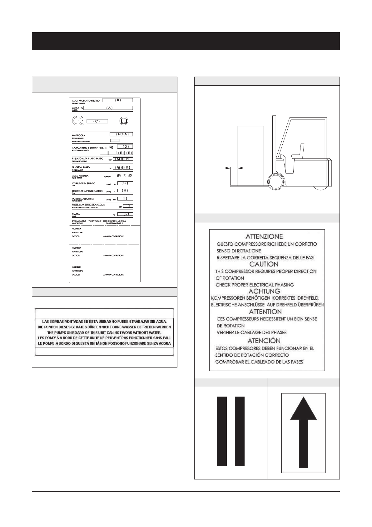
2.7 Safety labels
Identification of the unit Outside,
on the left -hand front column
Pump operation - Outside, on the right-hand front column
Instruction for the movimentation - Outside the packaging
Sequence phase control on the electrical board
Gravity centre - Base Instruction for the lifting
TENERE SU QUESTA LINEA
GANCIO DI SOLLEVAMENTO
KEEP LIFT HOOK
ON THIS LINE
MIN. 5 cm
Page 9

7
English
2 - Safety (continued)
Grounding connection on the electrical board,
adjacent to the connection
Read the instruction on the electrical board
Fitting identification - Adjacent to fittings
Electrical warning
Adjacent to the master switch
ATTENZIONE !
Prima di
aprire togliere
tensione
CAUTION !
Disconnect
electrical
supply before
opening
ACHTUNG !
Vor offn en des
gehauses
hauptschalter
ausschalten
ATENCION !
Cor tar la
corrente antes
de abrir
el aparato
ATTENTION !
Enlever
l’alimentation
electrique
avant d’ouvrir
Commissioning - Outside, on the left-hand front column
Final Test Certificate - Inside the external door
Page 10

8
2 - Safety (continued)
Identification of refrigerant - Below identification of the unit
Parameter configuration - Inside the electrical board
Pump drain - Outside, on the right-hand front column
Circuit drain - Outside, on the right-hand front column
Filter / flow switch - Outside, on the right-hand front column
ATTENTION! Don’t leave the unit with water inside hydraulic circuit during
winter or when it is in stand by.
ATTENZIONE! Non lasciare l’unità con acqua nel circuito idraulico durante
l’inverno o quando non è funzionante.
ATTENTION! Ne laissez pas l’unitè avec de l’eau dans le circuit hydraulique
pendant l’hiver ou quand elle ne travaille pas.
WARNUNG! Lassen Sie nicht das Wasser in die Schaltung während des
Winters oder wenn es nicht funktionient.
¡ATENCÍON! No deje el agua en el circuito hidráulico durante el invierno o
cuando no esta trabajando.
Page 11

9
English
2 - Safety (continued)
REFRIGERANT DATA SAFETY DATA: R410A
Toxicity Low
Contact with skin
If sprayed, the refrigerant is likely to cause frost burns. If absorbed by the skin, the danger is very limited;
it may cause a slight irritation, and the liquid is degreasing. Unfreeze the affected skin with water. Remove
the contaminated clothes with great care - in the presence of frost burns, the clothes may stick to the
skin. Wash with plenty of warm water the affected skin.
In the presence of symptoms such as irritation or blisters, obtain medical attention.
Contact with eyes
Vapours do not cause harmful effects. The spraying of refrigerant may
cause frost burns. Wash immediately with a proper solution or with tap
water for at least 10 minutes, and then obtain medical attention.
Ingestion
Very unlikely - should something happen, it will cause frost burns.
Do not induce vomiting. Only if the patient is conscious, wash out mouth with water and give some 250
ml of water to drink. Then, obtain medical attention.
Inhalation
R410A: remarkable concentrations in the air may have an anaesthetic effect, up to fainting.
The exposure to considerable amounts may cause irregular heartbeat, up to the sudden death of the
patient. Very high concentrations may result in the risk of asphyxia, due to the reduction in the oxygen
percentage in the atmosphere. Remove the patient to fresh air and keep warm and at rest.
If necessary, give oxygen. In case of breathing difficulties or arrest, proceed with artificial respiration.
In case of cardiac arrest, proceed with cardiac massage. Then, obtain medical attention.
Recommendations
Semiotics or support therapy is recommended. Cardiac sensitisation has been observed that, in
the presence of circulating catecholamines such as adrenalin, may cause cardiac arrhythmia and
accordingly, in case of exposure to high concentrations, cardiac arrest.
Prolonged exposure
R410A: a study on the effects of exposure to 50,000 ppm during the whole life of rats has identified the
development of benign testicle tumour.
This situation should therefore be negligible for personnel exposed to concentrations equal to or lower
than professional levels.
Professional levels R410A: Recommended threshold: 1000 ppm v/v - 8 hours TWA.
Stability R410A: Not specified
Conditions to avoid Do not use in the presence of flames, burning surfaces and excess humidity.
Hazardous reactions
May react with sodium, potassium, barium and other alkaline metals.
Incompatible substances: magnesium and alloys with magnesium concentrations > 2%.
Hazardous decomposition
products
R410A: Halogen acids produced by thermal decomposition and hydrolysis.
2.8 Safety regulations
Page 12

10
2 - Safety (continued)
REFRIGERANT DATA SAFETY DATA: R410A
General precautions
Do not inhale concentrated vapours. Their concentration in the atmosphere should not exceed the
minimum preset values and should be maintained below the professional threshold. Being more weighty
than the air, the vapour concentrates on the bottom, in narrow areas. Therefore, the exhaust system must
work at low level.
Respiratory system protection
If you are in doubt about the concentration in the atmosphere, it is recommended to wear a respirator
approved by an accident-prevention
Authority, of the independent or oxygen type.
Storage
Cylinders must be stored in a dry and fresh place, free from any fire hazard, far from direct sunlight or
other sources of heat, radiators etc.
Keep a temperature below 50 °C.
Protective clothing Wear overalls, protective gloves and goggles or a mask.
Accidental release measures
It is important to wear protective clothing and a respirator.
Stop the source of the leak, if you can do this without danger. Negligible leaks can be left evaporating
under the sun, providing that the room is well ventilated.
Considerable leaks: ventilate the room. Reduce the leak with sand, earth or other absorbing substances.
Make sure that the liquid does is not channelled into gutters, sewers or pits where the vapours are likely
to create a stuffy atmosphere.
Disposal
The best method is recovery and recycling. If this method is not practicable, dispose according to an
approved procedure, that shall ensure the absorption and neutralization of acids and toxic agents.
Fire fighting information R410A: Not flammable in the atmosphere.
Cylinders The cylinders, if exposed to fire, shall be cooled by water jets; otherwise, if heated, they may explode.
Protective fire fighting equipment In case of fire, wear an independent respirator and protective clothing.
2.8 Safety regulations (continued)
Page 13
11
English
2 - Safety (continued)
LUBRICANT OIL DATA SAFETY DATA: POLYESTER OIL (POE)
Classification Not harmful.
Contact with skin
May cause slight irritation. Does not require first aid measures. It is recommended to follow usual
personal hygiene measures, including washing the exposed skin with soap and water several times a day.
It is also recommended to wash your overalls at least once a week.
Contact with eyes Wash thoroughly with a suitable solution or tap water.
Ingestion Seek medical advice immediately.
Inhalation Seek medical advice immediately.
Conditions to avoid
Strong oxidising substances, caustic or acid solutions, excess heat.
May corrode some types of paint or rubber.
Protection of the respiratory
system
Use in well ventilated rooms.
Protective clothing
Always wear protective goggles or a mask. Wearing protective gloves is not mandatory, but is
recommended in case of prolonged exposure to refrigerant oil.
Accidental release measures
It is important to wear protective clothing and, especially, goggles.
Stop the source of the leak. Reduce the leak with absorbing substances (sand, sawdust or any other
absorbing material available on the market).
Disposal
The refrigerant oil and its waste will be disposed of in an approved incinerator, in conformity with the
provisions and the local regulations applicable to oil waste.
Fire fighting information
In the presence of hot liquid or flames, use dry powder, carbon dioxide or foam. If the leak is not burning,
use a water jet to remove any vapours and to protect the personnel responsible for stopping the leak.
Cylinders The cylinders exposed to a fire will be cooled with water jets in case of fire.
Fire fighting protective equipment In case of fire, wear an independent respirator.
2.8 Safety regulations (continued)
Page 14
12
3 - Transport, Handling and Storage
WQL / WQH / WQRC units are supplied fully assembled and tested
(except for accessories supplied loose in the units – absorbers, filter,
etc.). They are ready to be installed and started on the field.
R410A units are only charged with liquid refrigerant and with oil in the
quantity required for operation.
WARNING
The low pressure side of the refrigerating circuit
on R410A units shall be charged by means
of the service valve arranged on the thermal
expansion valve before the device is operated.
3.1 Inspection
The unit shall be immediately inspected upon receipt to find out any
damage since it has been delivered ex works and transported at the
customer’s risk. It is also necessary to make sure that all the parcels
specified on the delivery note have been delivered.
Any damage you may find out shall be immediately reported in writing
to the carrier. Even if the damage is only on the surface, please notify
our local representative too.
The manufacturer disclaims all responsibility for the shipment even if
it has provided for its organisation.
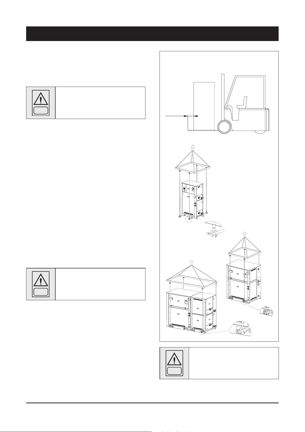
3.2 Handling
WQL / WQH / WQRC units are designed to be lifted from above, by
means of cables and eyebolts. A spacer shall be arranged between
the cables in order to prevent them from damaging the unit (see the
figure aside).
Before handling the devices, make sure the site you have chosen for
the installation can withstand its weight and support its mechanical
impact.
Avoid touching sharp parts while handling the unit.
WARNING
The unit shall never be placed on rollers.
Act as follows to lift and handle the unit:
Q
Insert and secure the eyebolts into the frame holes which have
been marked on purpose.
Q
Connect the cables to the eyebolts.
Q
Insert the spacer between the cables.
Q
Provide for hooking at the centre of gravity of the device.
Q
Cables shall have such a length that the angle they form with the
horizon when under tension is not less than 45°.
Space requirements request to handling
WARNING
While lifting and handling the unit, pay attention.
Otherwise, you might damage the finned block
of the coils arranged on both sides of the unit.
The side s of the unit sh all be protec ted by
cardboard or plywood sheets.
MIN. 5 cm
Page 15

13
English
3 - Transport, Handling and Storage
3.3 Anchoring
It is not essential to secure the unit to the foundations, unless in areas
where there is a serious risk of earth-quake, or if the appliance is
installed on the top of a steel frame.
3.4 Storage
If the unit is to be stored before the installation for some time, take
at least the following precautions to prevent damage, corrosion and/
or deterioration:
Q
Make sure all openings, such as for example water connections,
are well plugged and sealed.
Q
Never store the units in a room where temperature is above
50 °C (R410A units) or where the units are directly exposed to
the sunlight.
Q
Minimum storage temperature is -25 °C.
Q
Store the units in areas where minimum activity is likely to take
place in order to avoid any risk of accidental damage.
Q
Never use steam to clean the unit.
Q
Remove all the keys required to have access to the control panel
and give them to the person in charge of the field.
It is also recommended to provide for visual inspections at regular
intervals.
Page 16
14
4 - Installation
4.1 Positioning of the unit
DANGER
Before installing the unit, make sure that the
structure of the building and/or the supporting
surface can withstand the weight of the
appliance. The weights of the units are listed in
Chapter 8 of this manual.
These units have been designed for indoor installation on a solid
surface. Standard accessories include antivibrating rubber supports,
that must be positioned under the base.
When the unit is to be installed on the ground, it is necessary to
provide a concrete base, to ensure a uniform distribution of the
weights.
As a general rule, no special sub-bases are required. However, if the
unit is to be installed on the top of inhabited rooms, it is advisable
to rest it on spring shock absorbers (optional), that will minimise the
transmission of any vibration to the structures.
To choose the place of installation of the unit, bear in mind that:
Q the unit must not be installed in areas subject to flooding, under
gutters etc.
Q the place of installation must be have all the necessary spaces
for air circulation and maintenance operations (see Chapter 8).
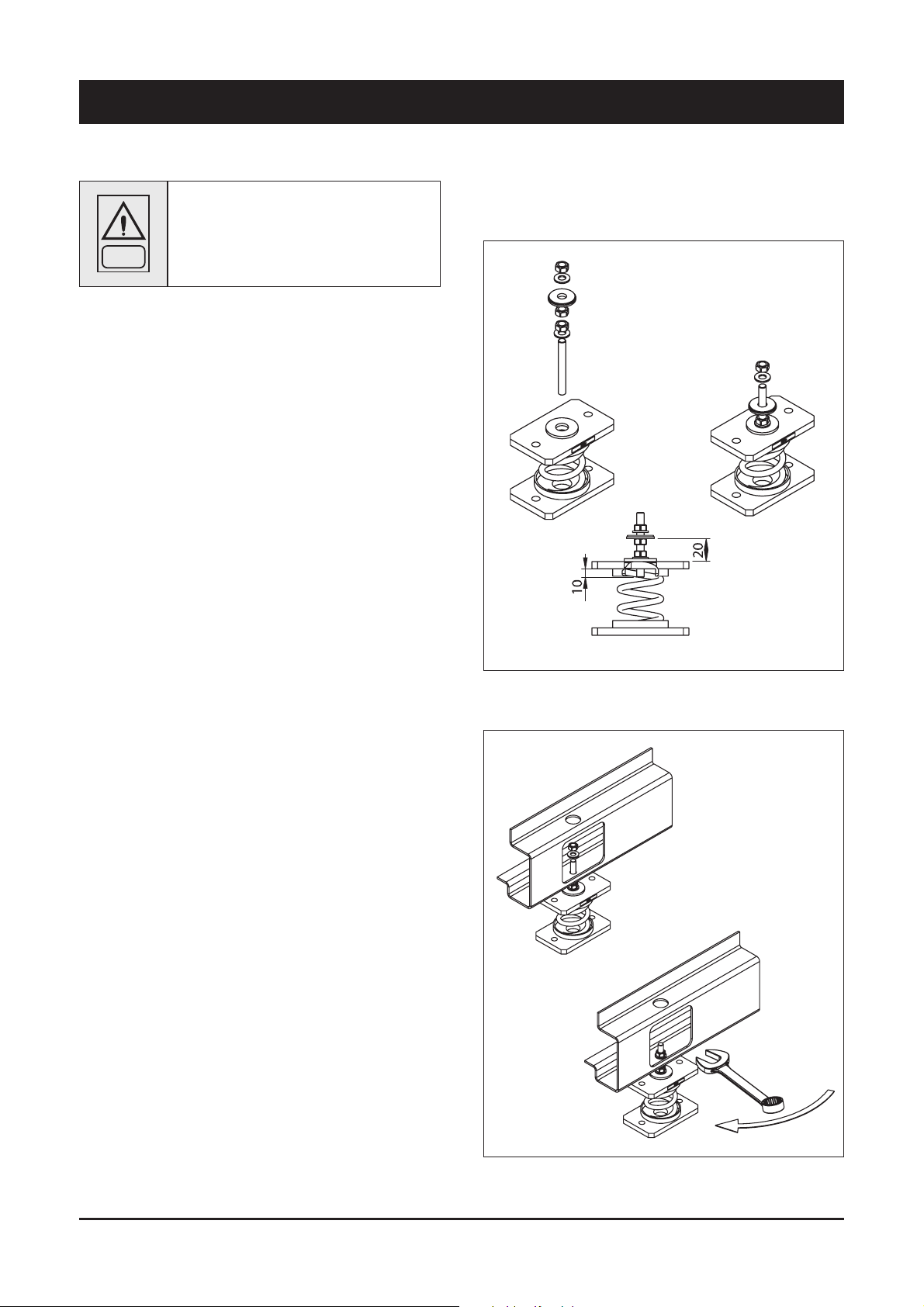
4.2 Spring Isolator Installation
Q
Prepare the base, that must be flat and plane.
Q
Lift the appliance and inser t shock absorbers as follows:
1) Procede to assemble the jack components. Fit the jack in the
threaded housing on the upper plate of the antivibration mount.
2) Fit the jack mounted on the antivibration mount in the hole in the
machine base.
Page 17

15
English
4 - Installation (continued)
4.3 Internal/external Water Circuit
The flow switch and the filter water, although not included in
the supply, must always be fitted such as plant components.
Their installation is mandatory for warranty.
WARNING
The internal/external water circuit shall guarantee
a constant water flow rate through the circulating
refrigerant/water heat exchangers under steady
operating conditions and in case of a load
variation.
The circuit shall be composed by the following elements:
Q
A circulation pump which can ensure the necessary flow rate
and head.
Q
The total content of the primary water circuit shall never be lower
than 5 l/kW in terms of refrigerating capacity. If the total water
volume in the primary circuit should be unable to reach such
a value, an additional heat-insulated storage tank should be
installed. This tank is intended to avoid any repetitive start of the
compressor.
Q
A membrane expansion tank complete with a safety valve and a
drain which shall be visible.
NOTE
The expansion tank shall be dimensioned in such
a way that it can absorb a 2% expansion of the
total volume of the water in the plant (exchanger,
pipelines, uses and storage tank, if available).
The expansion tank shall never be insulated
when the circulating fluid is not flowing through
it.
A water pressure differential switch is mounted as a standard. It will
stop the unit whenever a flow rate problem occurs.
In addition:
Q Install on/off valves (accessory) on the lines at the inlet and
outlet of the manifolds of the exchangers.
Q Arrange a by-pass complete with an on/off valve between the
manifolds of the heat exchangers.
Q Arrange air vent valves at the high points of the water lines.
Q Arrange drain points complete with plugs, clocks, etc. in the
proximity of the low points of the water lines.
Q Insulate the water lines to prevent the heat from blowing back
into the unit.
RECOMMENDED WATER COMPOSITION
PH 7,5 - 9
Electrical conductivity 10 - 500 µS/cm
Total hardness 4,5 - 8,5 dH
Temperature < 60 [°C]
Alkalinity (HCO
3
-
) 70-300 ppm
Alkalinity / Sulphates (HCO
3
-
/ SO
4
2-
) > 1 ppm
Sulphates (SO
4
2-
) < 70 ppm
Chlorides (Cl
-
) < 50 ppm
Free Chlorine < 0,5 ppm
Phosphates (PO
4
3-
) < 2 ppm
Ammonia (NH
3
) < 0,5 ppm
Ammonium Ion (NH
4
+
) < 2 ppm
Manganese Ion (Mn
2+
) < 0,05 ppm
Free Carbon Dioxide (CO
2
) < 5 ppm
Hydrogen Sufide (H
2
S) < 0,05 ppm
Oxygen Content < 0,1 ppm
Nitrates (NO
3
-
) < 100 ppm
Manganese (Mn) < 0,1 ppm
Iron (Fe) < 0,2 ppm
Aluminium (Al) < 0,2 ppm
Caution
If the water circuit is to be drained for a time exceeding one month, the
circuit must be fully charged with nitrogen to prevent any risk of corrosion
by differential venting
Page 18
16
4 - Installation (continued)
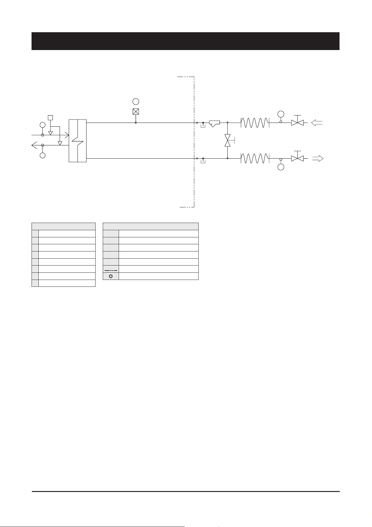
WQL - WQH 20/45 HYDRAULIC SYSTEM BASIC
COMPONENTS
1 Plate heat exchanger
2 Water filter
3 Water outlet
4 Water inlet
5 Globe valve
6 Flexible pipes
7 By-pass valve
8 Pressure point/drainage
SAFETY/CONTROL DEVICES
A Water differential pressure switch.......( )
B Inlet water temperature sensor
C Outlet water temperature sensor
D Vent valve
E Thermometer
Unit side
Probes
1
4
2
E
E
3
5
5
6
6
7
INLET
OUTLET
D
C
B
A
8
8
Page 19
17
English
4 - Installation (continued)
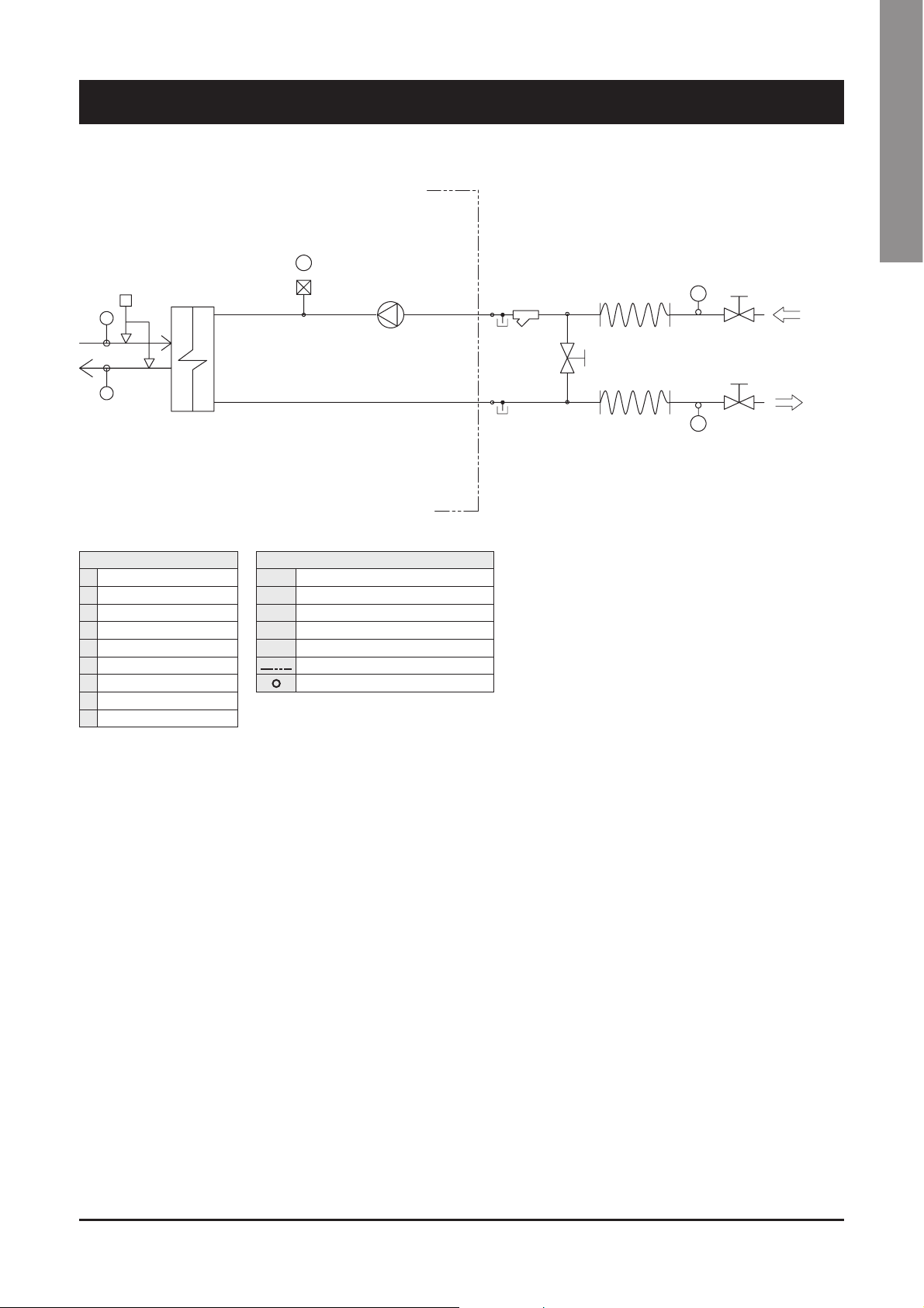
WQL - WQH 20/45 HYDRAULIC SYSTEM 1P CONDENSER
COMPONENTS
1 Plate heat exchanger
2 Pump
3 Water filter
4 Water outlet
5 Water inlet
6 Globe valve
7 Flexible pipes
8 By-pass valve
9 Pressure point/drainage
SAFETY/CONTROL DEVICES
A Water differential pressure switch.......( )
B Inlet water temperature sensor
C Outlet water temperature sensor
D Vent valve
E Thermometer
Unit side
Probes
2
OUTLET
INLET
8
7
7
6
6
4
E
E
3
5
1
D
A
B
C
9
9
Page 20

18
4 - Installation (continued)
WQL - WQH 20 / 45 HYDRAULIC SYSTEM 1P EVAPORATOR
COMPONENTS
1 Plate heat exchanger
2 Pump
3 Water filter
4 Pressure expansion tank
5 Water outlet
6 Water inlet
7 Globe valve
8 Flexible pipes
9 By pass valve
10 Pressure point/drainage
SAFETY/CONTROL DEVICES
A Water differential pressure switch.......( )
B Inlet water temperature sensor
C Outlet water temperature sensor
D Vent valve
E Thermometer
Unit side
Probes
C
B
A
D
1
6
3
E
E
5
7
7
8
8
9
INLET
OUTLET
2
4
10
10
Page 21

19
English
4 - Installation (continued)
WQL - WQH 50 / 190 HYDRAULIC SYSTEM BASIC
1- C
4
2
E
E
3
5
5
6
6
7
INLET
OUTLET
C
B
A
A
B
C
OUTLET
INLET
7
6
6
5
5
3
E
E
2
4
1- E
8
8
8
8
COMPONENTS
1C Condenser
1E Evaporator
2 Water filter
3 Water outlet
4 Water inlet
5 Globe valve
6 Flexible pipes
7 By pass valve
8 Pressure point/drainage
SAFETY/CONTROL DEVICES
A Water differential pressure switch.......( )
B Inlet water temperature sensor
C Outlet water temperature sensor
D Vent valve
E Thermometer
Unit side
Probes
Page 22

20
4 - Installation (continued)
WQL - WQH 50 / 190 HYDRAULIC SYSTEM 1P CONDENSER 1P EVAPORATOR
COMPONENTS
1C Condenser
1E Evaporator
2 Pump
3 Water filter
4 Pressure expansion tank
5 Water outlet
6 Water inlet
7 Globe valve
8 Flexible pipes
9 By pass valve
10 Pressure point/drainage
SAFETY/CONTROL DEVICES
A Water differential pressure switch.......( )
B Inlet water temperature sensor
C Outlet water temperature sensor
D Vent valve
E Thermometer
Unit side
Probes
C
B
A
D
1- E
6
3
E
E
5
7
7
8
8
9
INLET
OUTLET
4
2
2
C
B
A
D
1- C
6
3
E
E
5
7
7
8
8
9
INLET
OUTLET
10
10
10
10
Page 23

21
English
4 - Installation (continued)
WQL - WQH 50 / 190 HYDRAULIC SYSTEM 2P CONDENSER 2P EVAPORATOR
COMPONENTS
1C Condenser
1E Evaporator
2 Pump
3 Water filter
4 Pressure expansion tank
5 Water outlet
6 Water inlet
7 Globe valve
8 Flexible pipes
9 By pass valve
10 Non-return valve
11 Pressure point/drainage
SAFETY/CONTROL DEVICES
A Water differential pressure switch.......( )
B Inlet water temperature sensor
C Outlet water temperature sensor
D Vent valve
E Thermometer
F Water safety valve... (6BAR)
Unit side
Probes
2
OUTLET
INLET
9
8
8
7
7
5
E
E
3
6
1- C
D
A
B
C
2
2
2
4
OUTLET
INLET
9
8
8
7
7
5
E
E
3
6
1- E
D
A
B
C
F
F
10
10
10
10
11
11
11
11
Page 24

22
4 - Installation (continued)
4.4 Water connections
WARNING
The attachments at the water inlet and outlet
shall be connected in compliance with the
instructions which can be found on the labels in
the proximity of the attachments.
Connect the water lines of the plants with the attachments of the unit
whose diameters and positions are shown by Chapter 8.
4.5 Power supply
DANGER
Before carrying out any operations on the
electrical system, make sure that the unit is
deenergised.
DANGER
It is important that the appliance is grounded.
DANGER
The company in charge of the installation shall
conform to the standards applicable to outdoor
electrical connections.
The manufacturer may not be held liable for any damage and/or
injury caused by failure to comply with these precautions.
The unit conforms to EN 60204-1.
The following connections shall be provided:
Q A 3-phase and grounding connection for the power supply
circuit.
Q The electrical distribution system shall meet the power absorbed
by the appliance.
Q The disconnecting and magnetothermal switches must be sized to
control the starting current of the unit.
Q The power supply lines and the insulation devices must be
designed in such a way that every line independent.
Q It is recommended to install differential switches, to prevent any
damage caused by phase drops.
Q The compressors are supplied through contactors controlled
from the control panel.
Q Each motor is provided with an internal safety thermal device
and external fuses.
Q The power supply cables must be inserted into dedicated
openings on the front of the unit, and the will enter the electrical
board through holes drilled on the bottom of the board.
Page 25

23
English
4 - Installation (continued)
4.6 Electrical connections
The unit must be installed on site according to the Machinery
Directive (2006/42/EC), the Low Voltage Directive (2006/95/EC),
the Electromagnetic Interference Directive (2004/108/EC) and
the usual procedures and standards applicable in the place of
installation.
The unit must not be operated if its installation has not been
carried out according to the instructions provided in this manual.
The power supply lines must consist of insulated copper
conductors, dimensioned for the maximum absorbed current.
Connection to terminals must be performed according to the diagram
of connections (User’s Terminal Box) provided in this manual and
according to the wiring diagram which accompanies the unit.
WARNING
Before connecting the power supply lines, check
that the available voltage value does not exceed
the range specified in the Electric Data (Chapter
8).
For 3-phase systems, check also that the unbalance between the
phases does not exceed 2%. To perform this check, measure the
differences between the voltage of each phase couple and their mean
value during operation.
The maximum % value of these differences (unbalance) must not
exceed 2% of the mean voltage.
If the unbalance is unacceptable, contact the Energy Distributor to
solve this problem.
WARNING
Supplying the unit through a line whose
unbalance exceeds the permissible value will
automatically void the warranty.
Page 26

24
4 - Installation (continued)
Electrical Connections
Page 27

25
English
5 - Start-Up
WARNING
The unit must be started for the first time by
personnel suitably trained by one Authorised
Service Centre. Failure to meet this requirement
will immediately void the warranty.
NOTE
The operations carried out by authorised
personnel are limited to the start-up of the unit,
and do not include any other operation on the
plant, such as, for example, electrical and
hydraulic connections etc.
All the other operations before start-up, including
oil pre-heating for at least 12 hours, must be
performed by the Installer.
5.1 Preliminary check
The checks listed below shall be performed before star ting the unit
and before the arrival of the personnel authorised.
Q Check the section of power supply and grounding cables; make
sure that terminals are tightened and check the correct operation
of contactors, with the main switch open.
Q Check that any voltage and phase variation in the power supply
does not exceed the prefixed thresholds.
Q Connect the contacts of the flow switch and the thermal relay of
the pump and of the other devices (if any), to terminals 4-5/6-7
and 1-2, respectively.
Q Check that the components of the external water circuit (pump,
user equipment, filters, power supply tank and reservoir, if any)
have been installed properly, and according to the manufacturer’s
instructions.
Q Check the filling of the hydraulic circuits, and make sure that
the fluid circulation is correct, without any trace of leaks and air
bubbles. If you use ethylene glycol as antifreeze, check that its
percentage is correct (do not exceed 35% glycol percentage).
Q Check that the direction of rotation of the pumps is correct, and
that fluids have been circulating for at least 12 hours for both
pumps. Then, clean the filters on the suction side of the pumps.
Q Adjust the liquid distribution network in such a way that the flow
rate is within the specified range.
Q Check that the water quality is up to the specifications.
Q Check that oil heaters, if any, have been turned on at least 12
hours before.
5.2 Start-up
Start-up sequence:
Q Turn on the Main switch (at least 12 hours before).
Q Check that the oil in the compressor has reached the requested
temperature (the minimum temperature outside the pan must be
approx. 40°C) and that the auxiliary control circuit is energised.
Q Check the operation of all the external equipment, and make sure
that the control devices of the plant are properly calibrated.
Q Start the pump and check that the water flow is correct.
Q Set the desired fluid temperature on the control board.
Q Start the appliance (see Chapter 6).
Q Check the correct direction of rotation of compressors. Scroll
compressors cannot compress the refrigerant when they rotate
in the opposite direction. To make sure that they are rotating in
the correct direction, simply check that, just after the start-up
of the compressor, the pressure drops on the LP side and rises
on the HP side. Furthermore, if a scroll compressor rotate in
the opposite direction, there is a considerable rise in the sound
level of the unit, as well as in a dramatic reduction of current
absorption compared to normal values. In case of wrong
rotation, the scroll compressor can be definitely damaged. Phase
monitor is assembled in the unit as a standard to prevent wrong
compressors rotation.
Q After about 15 minutes of operation check that there are no
bubbles, through the sight glass on the liquid line.
WARNING
The presence of bubbles may indicate that a
part of the refrigerant charge has been released
in one or more points. It is important to remove
these leaks before proceeding.
Q Repeat the start-up procedure after removing the leaks.
5.3 Checking the operation
Check the following:
Q The temperature of the water entering the evaporator/condenser.
Q The temperature of the water leaving the evaporator/condenser.
Q The level of the water flow rate in the evaporator/condenser.
Q The current absorption upon the start of the compressor and in
case of stabilised operation.
Check that the condensing and evaporation temperatures, during
operation at high and low pressure detected by the pressure gauges
of the refrigerant, are within the following range:
(On the units not provided with HP/LP pressure gauges for the
refrigerant, connect a pressure gauge to the Shrader valves on the
refrigeration circuit).
HP side
Approx. 3-5 °C above the temperature of water
leaving the condenser, for R410A units.
LP side
Approx. 2 to 4 °C below the temperature of the
leaving chilled water, for R410A units.
5.4 Delivery to the customer
Q Train the user according to the instructions provided in Section 6.
Page 28

26
6 - Control
6 General information
Introduction
This document contains the information and the operating instructions
for WQL/WQH/WQRC units.
Main characteristics
– simple user interface with possibility to customize keys functions
and to set menus visibility
– parameter setting through keyboard or PC
– thermoregulation ¤ inlet/outlet water probe, according to
customer need / application
– auto-adaptive set-point
– dynamic set-point
– sanitary hot water and anti-legionella weekly scheduling
– alarm log
– analogue input (to be set)¤NTC, 4..20mA, 0..1V, 0..5V, 0..10V
– digital input¤to be set by parameter
– automatic changeover
– 0-10V analogue condensation control
– boiler / electrical resistances management for heating
integration
– electrical resistance management for sanitary hot water
– advanced pump management (internal/external circuit)
The following accessories can be also connected:
– multi Function Key (MFK) to upload / download parameters map
– serial communication RS485 card; to connect the control to a
BMS network
– remote display terminal
– wire remote control
6.1 Control of WQL/WQH/WQRC units, single/
double compressor
WQL/WQH/WQRC units are provided with a microprocessor card
fully programmed by default for the control of a heat pump unit.
General information
The figure shows the terminal. It is provided with a 4 red digits with
7 segments with decimal point led, 18 LED and 4 buttons, so as
to allow the programming of the control parameters (setpoint,
differential bands, alarm thresholds) and the main operations to be
carried out by the user.
6.2 Keypad functions
KEY
LINKED
FUNCTION
KEYS
COMBINATION
DESCRIPTION
EXTENDED PUSH
(MORE THAN 3s)
LINKED FUNCTION
UP
DOWN
ESC
SET
SINGLE PUSH
(PUSH /RELEASE)
MENU/NOTES
MENU/NOTES
- Increase value
- Go to next label
- Change Set-point
- Enable Sanitary Hot Water
function
- Enable / Disable
/
/
/
/
- Decrease value
- Go to previous label
- Change Set-point (if UI25 =1)
- Stand-by
- Local ON/OFF
- Time slots menu
- Stand-by ¤ ON
- Enter in “Program Menu” - Program Menu
- Exit without saving
- Go to previous level
- Mode menu- Change mode
- Confirm value / exit with setting
saving
- Go to next level
- Go to status menu
- Display menu- Main display
Page 29

27
English
6 - Control (continued)
ICON / COLOR
LED N°*
STEADY ICON
DESCRIPTION
BLINKING ICON
ICON
- Alarm ON
First capacity step
Second capacity step
Primary circuit pump
Source circuit pump
Electrical heater
Sanitary hot water valve / pump
Boiler
/ RED
1
2
3
4
5
6
7
/ GREEN
/ GREEN
/ GREEN
/ GREEN
/ GREEN
/ RED
/ RED
/ RED
/ RED
/ RED
- Mode: HEATING
- Current HR
- Time slots activ.
- Mode: COOLING
/
/
/
- Mode: STAND-BY
- Configurable
Not used
Menu surf
- Alarm QUIT
- Antifreeze+Heat pump ON
- Heating mode by remote
- HR setting
- Time slots programming
- Cooling mode by remote
/
/
/
- Stand-by mode by remote
- Configurable
Not used
/
6.3 Folder structure
Folder structure is composed of totally four menus
1) Main display¤used to set what to display without acting on any
key
– Ai¤analogue input (temperature, pressure)
– rtC¤room time clock
– SetP¤standard set-point
– SetR¤corrected set-point (according to climatic correction,
etc.)
2) Operating mode¤used to set operating mode
– StbY¤stand-by
– HEAT¤heating
– COOL¤cooling
– AS¤sanitary hot water
3) Status¤used to show resources values
– Ai (AIL/AIE/Air)¤analogue inputs (main board / expansion
board / remote terminal)
– di (diL/diE)¤digital inputs (main board / expansion board)
– AO (AOL/AOE)¤ analogue outputs (main board/expansion
board)
– CL (HOUr/dAtE/YEAr)¤clock
– AL (Er00¤Er98)¤alarms
– SP¤standard set-point
– Sr ¤ corrected set-point (according to climatic correction,
etc.)
4) Program¤define parameters, functions, password and to display
alarm log
6.4 Menu structure
“Program” menu is composed of totally four folders
1) Parameters¤change unit parameters
2) Functions¤manual operations (switch ON / switch OFF, alarm
quit, historic alarm delete, multi function key use)
3) Password¤define visibility levels for parameters/folders
4) Alarm log¤display alarm log
Parameter folder gives access to following sub-folders
– CL/CE/Cr/CF¤configure device I/O (L¤local; E¤expansion; r
¤remote; F¤serial)
DQDORJXH LQSXWV W\SH RI SUREH UDQJH GLIIHUHQWLDO ORJLF
function)
GLJLWDOLQSXWVORJLFIXQFWLRQ
GLJLWDORXWSXWVORJLFIXQFWLRQ
DQDORJXHRXWSXWVUDQJH
VHULDOFRQILJXUDWLRQFRPPXQLFDWLRQSDUDPHWHUV
– TR¤define thermoregulation parameters
VHWSRLQWPD[PLQK\VWHUHVLV
W\SHSURSRUWLRQDOGLIIHUHQWLDO
SUREHVHOHFWLRQ
– ST¤define operating status
FRROLQJRQO\
KHDWLQJRQO\
VFRROLQJDQGKHDWLQJ
FKDQJHRYHU
– CP¤configure compressor parameters (type/number/timing)
– PI/PE ¤ define primary circuit / source side circuit pump
parameters / functions
RSHUDWLQJPRGHGLVDEOHDOZD\V2121LIFRPSUHVVRU21
GLJLWDODQDORJXHFRQWURO
DQWLVWLFNLQJ
DQWLIUHH]H
– BR ¤ control the parameters for an additional step for heating
and for sanitary hot water integration (boiler)
RSHUDWLQJPRGHGLVDEOHGLIIHUHQWLDO¤ fixed or in function of
outdoor air temperature)
VHWSRLQWK\VWHUHVLV
– DS¤define set-point offset (dynamic set-point) depending on
DQDORJXHLQSXW«9«9«9«P$
RXWGRRUDLUWHPSHUDWXUH
URRPWHPSHUDWXUH
– AD¤ simulate an electronic inertial accumulator, acting on set-
point and hysteresis (adaptive function), by confronting minimum
/ effective ON-OFF time
– AS¤define sanitary hot water management parameters
RSHUDWLQJPRGHGLVDEOHVDQLWDU\KRWZDWHUYDOYHUHVLVWDQFH
/ pump)
VHWSRLQWK\VWHUHVLV
DQWLOHJLRQHOODIXQFWLRQ
– HP¤define heat pump block management parameters
RXWGRRUDLUWHPSHUDWXUH
WKHUPRUHJXODWLRQWHPSHUDWXUH
GLJLWDOLQSXW
– PL ¤ define capacity limitation to protect the unit (high/low T,
high/low P)
– TE ¤ define time slots management (different operating daily
profiles)
– AL¤define alarms management (automatic / manual reset, by-
pass time, sampling)
Page 30

28
Code Alarm unit description CPS status
RESET
auto/man
Internal circuit
pump status
Internal circuit
pump status
Sanitary valve /
heater status
Er00 General alarm OFF A OFF OFF OFF
Er01 High pressure circuit OFF M
Er05 Low pressure circuit OFF A¤M
Er10 Thermal protection - compressor 1
OFF
CPS 1
M
Er11 Thermal protection - compressor 2
OFF
CPS 2
M
Er20 Plant side flow switch OFF M OFF
(1)
OFF
(1)
Er21 Thermal protection - plant side pump OFF A¤M OFF
Er25 Source side flow switch OFF M
OFF
(1)
Er26 Thermal protection - source side pump OFF A¤M
OFF
Er30 Plant side antifreeze OFF A
Er31 Source side antifreeze OFF A
Er35 Water high temperature OFF A
Er41
Thermal protection - source side pump (in case of
condensing control option)
OFF M
OFF
Er45 Clock failure A
Er46 Clock to be set A
Er47 LAN communication error A
Er48 Legionella set-point not reached A
Er60 RWT probe plant side failure OFF A OFF
Er61 LWT probe plant side failure OFF A OFF
Er63 RWT probe plant side failure OFF A
Er64 LWT probe plant side failure OFF A
Er66 Sanitary hot water probe failure OFF A
Er67 Visualization probe (T/P) failure A
Er68 Outdoor air temperature probe failure OFF A
Er69 High pressure transducer failure OFF A
Er73 Dinamic set-point failure A
Er80 Configuration error A OFF
Er81 Compressor maintenance M
Er85 Plant side pump maintenance M
Er86 Source side pump maintenance M
Er90 Alarm hystoric record overcoming M
6 - Control (continued)
6.5 Alarm list
1) If alarm is manual type
Page 31

29
English
7 General Description
7.1 Introduction
The new range of water cooled chillers, includes 14 different
capacities, fit for medium-sized residential, commercial and industrial
applications.
All these 14 sizes are available in three versions:
Q WQL: cooling only unit, requires a cooling tower or a dry cooler
for heat dissipation purposes
Q WQRC: needs a remote condenser for heat dissipation purposes
Q WQH: heat pump, the hot water’s outlet temperature can reach
55°C (in heating mode), useful for sanitary water.
7.2 General Specifications
These units are provided with cabinets made of ovenpainted
galvanised sheet panels. These panels are soundproof, thanks to
deadening sleeve (optional), to ensure absolutely noiseless operation.
All units are factory-assembled and receive the necessary charge
of refrigerant and oil (except for WQRC, which are shipped with a
nitrogen charge) for compressors, so that they can be promptly
installed. Every single unit is tested by making the water circulate
through the heat exchangers, in order to check the performance of
the refrigeration circuit.
7.3 Compressors
All compressors are of Scroll hermetic type, and the motor is cooled
by the sucked gas; they are provided with an oil heater. 20 to 45
models have a compressor, while the 50 to 190 models are equipped
with two compressors in tandem.
All compressors are mounted on rubber shock absorbers, so as to
minimise the sound level and the vibration transmission.
7.4 Refrigeration circuits
The refrigeration circuit is provided with a thermostatic expansion
valve, dehydrating cartridge filter, sight glass with a colour-change
humidity indicator, HP and LP pressure switches.
WQH units feature also a 4-ways valve and check valves in order to
always run expansion valve and filter in the same way.
WQRC units feature also a solenoid valve and a liquid receiver.
7.5 Evaporator
The direct-expansion evaporator consists of a welded stainless steel
plate-type heat exchanger.
The evaporator’s standard accessories include a closed-cell
polyurethane sleeve, and a water pressure differential switch.
7.6 Condenser (except for WQRC)
The water-cooled condenser consists of a welded stainless steel
plate-type heat exchanger.
The condenser’s standard accessories include a closed-cell
polyurethane sleeve, and a water pressure differential switch.
7.7 Switchboard
All the electrical devices required to operate the unit are housed
inside a separate compar tment, which can be accessed from the
front side of the appliance, via a panel secured by lock screws.
The switchboard, manufactured to CE standards, includes the master
disconnector with external handle locked in the opening position,
contactors and thermal protections, fuses for the control circuit,
sequence phase controller, water sensor, electronic controller, HP
and LP pressure switch, timer (to prevent frequent star ts), ON/OFF
switch and terminal board.
7 - General Description
Page 32

30
5
2
4
6
1
3
S
A
C
S
BS
MECHANICAL EXPANSION
VALVE (STANDARD)
ELECTRONIC EXPANSION
VALVE (OPTIONAL)
3
4
BT
UNIT
CONTROL
EXV
CONTROL
7
SUCTION LINE
ST
F
E
H
D
G
AT
S
4
3
5
1
2
S
A
AT
S
BS
MECHANICAL EXPANSION
VALVE (STANDARD)
ELECTRONIC EXPANSION
VALVE (OPTIONAL)
6
7
BT
UNIT
CONTROL
EXV
CONTROL
10
SUCTION LINE
ST
H
D
G
6
7
8
9
4
6
S
ON
5
2
S
A
AT
S
B
88
8
8
MECHANICAL EXPANSION
VALVE (STANDARD)
1
E
F
3
G
H
7
C
D
ST
UNIT
CONTROL
EEV
CONTROL
BT
ELECTRONICAL EXPANSION
VALVE (OPTIONAL)
4
5
9
S
7 - General Description (continued)
SAFETY / CONTROL DEVICES
A High pressure switch (42 Bar)
B Low pressure switch (2 Bar)
AT High pressure transducer (optional)
BT Low pressure transducer
ST Suction temperature probe
S 5/16” Shrader connection (service only)
C Water differential pressure switch
F Inlet water temperature sensor
E Outlet water temperature sensor
D Water differential pressure switch
G Inlet water temperature sensor
H Outlet water temperature sensor
Pipe connection with Schrader valve
SAFETY / CONTROL DEVICES
A High pressure switch (42 Bar)
B Low pressure switch (2 Bar)
AT High pressure transducer (optional)
BT Low pressure transducer
ST Suction temperature probe
S 5/16” Shrader connection (service only)
D Water differential pressure switch
G Inlet water temperature sensor
H Outlet water temperature sensor
Pipe connection with Schrader valve
SAFETY / CONTROL DEVICES
A High pressure switch (42 Bar)
B Low pressure switch (2 Bar)
AT High pressure transducer (optional)
BT Low pressure transducer
S 5/16” Shrader connection (service only)
C Water differential pressure switch
F Inlet water temperature sensor
E Outlet water temperature sensor
D Water differential pressure switch
G Inlet water temperature sensor
H Outlet water temperature sensor
Pipe connection with Schrader valve
COMPONENTS
1 Compressor
2 Condenser
3 Drier filter
4 Sight glass
5 Mechanical expansion valve
6 Evaporator
7 Electronic expansion valve
COMPONENTS
1 Compressor
2 Globe valve
3 Globe valve
4 Liquid receiver
5 Solenoid valve
6 Drier filter
7 Sight glass
8 Mechanical expansion valve
9 Evaporator
10 Electronic expansion valve
COMPONENTS
1 Compressor
2 4 way valve
3 Condenser
4 Drier filter
5 Sight glass
6 Mechanical expansion valve
7 Evaporator
8 Check valve
9 Electronic expansion valve
WQL 20 - 45 Refrigeration System
WQRC 20 - 45 Refrigeration System
WQH 20 - 45 Refrigeration System
Page 33

31
English
5
2
4
6
3
S
A
C
S
S
MECHANICAL EXPANSION
VALVE (STANDARD)
ELECTRONIC EXPANSION
VALVE (OPTIONAL)
3
4
BT
UNIT
CONTROL
EXV
CONTROL
7
SUCTION LINE
ST
F
E
H
D
G
8
B
I
1
OIL EQUAL.
AT
S
4
3
5
2
S
A
AT
S
B
S
MECHANICAL EXPANSION
VALVE (STANDARD)
ELECTRONIC EXPANSION
VALVE (OPTIONAL)
6
7
BT
UNIT
CONTROL
EXV
CONTROL
10
SUCTION LINE
ST
H
D
G
6
7
8
9
OIL EQUAL.
1
I
4
6
S
ON
5
2
S
A
S
B
88
8
8
MECHANICAL EXPANSION
VALVE (STANDARD)
E
F
3
G
H
7
C
D
ST
UNIT
CONTROL
EEV
CONTROL
BT
ELECTRONICAL EXPANSION
VALVE (OPTIONAL)
4
5
9
OIL EQUAL.
1
10
I
AT
S
7 - General Description (continued)
SAFETY / CONTROL DEVICES
A High pressure switch (40.5 Bar)
B Low pressure switch (2 Bar)
BT Low pressure transducer
AT High pressure transducer (optional)
S 5/16” Shrader connection (service only)
C Water differential pressure switch
F Inlet water temperature sensor
E Outlet water temperature sensor
D Water differential pressure switch
G Inlet water temperature sensor
H Outlet water temperature sensor
I PED pressure valve (45 Bar)
Pipe connection with Schrader valve
SAFETY / CONTROL DEVICES
A High pressure switch (40.5 Bar)
B Low pressure switch (2 Bar)
AT High pressure transducer (optional)
BT Low pressure transducer
ST Suction temperature probe
S 5/16” Shrader connection (service only)
D Water differential pressure switch
G Inlet water temperature sensor
H Outlet water temperature sensor
I PED pressure valve (45 Bar)
Pipe connection with Schrader valve
SAFETY / CONTROL DEVICES
A High pressure switch (40.5 Bar)
B Low pressure switch (2 Bar)
BT Low pressure transducer
AT High pressure transducer (optional)
S 5/16” Shrader connection (service only)
C Water differential pressure switch
F Inlet water temperature sensor
E Outlet water temperature sensor
D Water differential pressure switch
G Inlet water temperature sensor
H Outlet water temperature sensor
I PED pressure relief valve (45 Bar)
Pipe connection with Schrader valve
COMPONENTS
1 Compressor
2 Condenser
3 Drier filter
4 Sight glass
5 Mechanical expansion valve
6 Evaporator
7 Electronic expansion valve
8 Desuperheater
COMPONENTS
1 Compressor
2 Globe valve
3 Globe valve
4 Liquid receiver
5 Solenoid valve
6 Drier filter
7 Sight glass
8 Mechanical expansion valve
9 Evaporator
10 Electronic expansion valve
COMPONENTS
1 Compressor
2 4 way valve
3 Condenser
4 Drier filter
5 Sight glass
6 Mechanical expansion valve
7 Evaporator
8 Check valve
9 Electronic expansion valve
10 Desuperheater
WQL 50 - 190 Refrigeration System
WQRC 50 - 190 Refrigeration System
WQH 50 - 190 Refrigeration System
Page 34

32
7 - General Description (continued)
7.8 Accessories
Water Filter
1-1/2” filter (20-45 units) and 2-1/2” filter (50-190 units) is supplied
loose and has to be mounted by the customer. (both evaporator and
condenser side)
Anti-Vibration Kit
Anti-vibration kit made of special rubber pad is provided together
with the unit.
Water Differential Pressure Switch
Water differential pressure switch is mounted as standard in the unit.
Flow switch kit
Flow switch kit is available as an accessory. It is supplied loose
and as to be mounted by the customer. Connect terminals of the
evaporator flow switch with terminals 4-5 of the electrical box.
Connect terminals of the condenser flow switch with terminals 6-7 of
the electrical box.
Pumps
Min. 100 kPa head pressure pump be mounted as an option both
evaporator and condenser side (sizes 20 to 45).
One or two 100-150 [kPa] head pressure pump can be mounted as
an option (1/2P-SP) both evaporator and condenser side (sizes 50 to
190).
One or two 200-250 [kPa] head pressure pump can be mounted as
an option (1/2P-HP) both evaporator and condenser side (sizes 50
to 190).
Phase Monitor Kit
It is assembled on the unit as a standard.
Airway Packaging
Complete wooden package for units without refrigerant and with
nitrogen precharge. No refrigerant charge is shipped loose with
the unit. The customer has to fill the unit through the apposite
connection.
On/Off Remote Kit
It enables the operator to power on the unit when it is in standby
mode, to display alarms and to switch over cooling – heat pump. The
kit will include a 3 metre long cable for installation on the wall.i.
Sequencer kit - 4 units
It can easily pilot up to 4 units fitted in parallel, 50 metres maximum
apart.
Gauge kit
Gauge kit is available as an option.
Domestic hot water kit
It is provided as an accessory to allow the unit managing the control
of a 3 ways valve, in order to switch water flow from plant to boiler.
A water probe as to be installed remotely inside the boiler in order to
read sanitary hot water temperature.
Connect water probe terminals to terminal AI5 - GND on the electrical
box (refer to Chapt. 4).
Connect 3 ways valve terminals to terminal 93 - 8 of the electrical
box (refer to Chapt. 4).
Domestic hot water integration kit
It is provided as an option/accessory to allow the unit managing the
control of a relais for an electrical heater, in order to integrate the
production of sanitary hot water.
Connect the relais to terminal DO5-12V of the electrical box (refer to
Chapt. 4).
SOURCE
PLANT
WATER
PROBE
DHW
DCW
3 WAYS
VALVE
SOURCE
PLANT
WATER
PROBE
DHW
DCW
3 WAYS
VALVE
ELECTRICAL
HEATER
Page 35

33
English
7 - General Description (continued)
Additional heating device kit
It is provided as an option/accessory to allow the unit managing the
control of an additional heating device (a boiler in example), in order
to integrate the production of hot water.
Connect the addi tional heating device to terminal 33-8 of the
electrical box (refer to Chapt. 4).
Climatic control kit
It is provided as an accessory to allow the unit managing the control
of water temperature, according outdoor air temperature. Connect
outdoor air temperature probe terminals to terminal AIE5 - GND on
the electrical box (refer to Chapt. 4).
Antivibrating supports (AVM)
Isolating spring supports, equipped with bolts for fastening to
the base. They are supplied separated from the unit and must be
mounted on site by the customer, at his own expense.
Remote wall terminal
Makes it possible to check the unit through a remote terminal, up to a
maximum distance of 100 meters.
RS-485 protocol Modbus
A communication interface makes it possible to control and manage
the unit from a local station, with RS485 connection.
It is possible to obtain the remote control and the management, by
inserting the control into the management plant of the building.
Pressostatic Valve Kit (20-45 units)
This item is available only for cooling only units. The pressostatic
valve, controlled by condensing pressure, regulates the water flow
to maintain the condensing temperature at the desired value (the
condensing temperature of +40 °C is recommended).
Condensing control kit
It is provided as an option/accessory to allow the unit managing
the control of condensation, in case very cold water (from a well in
example) is entering the condenser . A 0-10V signal (terminal 2-3 of
the electrical box / refer to Chapt. 4) is available to manage a variable
flow device (in example 2/3 ways modulating valve, inverter pump).
SOURCE
BOILER
WATER
PROBE
DHW
DCW
3 WAYS
VALVE
DISCHARGE
LINE
PLANT
0-10V
INV
2/3 H
H
NORD
YES
NO
WATER COMPENSATION RULE - HEATING MODE
OAT [°C]
55
50
45
40
35
30
25
-20 -15 -10 -5 0 5 10 15 20 25
LWT [°C]
WATER COMPENSATION RULE - COOLING MODE
OAT [°C]
17
15
13
11
9
7
5
3
1
10 15 20 25 30 35 40 45
LWT [°C]
Page 36

34
8.1 Pressure drops
8 - Technical Data
PRESSURE DROP IN THE EVAPORATOR 20 to 45
20 25 30 35 40 45
K kPa/(l/s)
2
17,0 16,5 15,9 15,6 11,4 7,97
Minimum flow rate l/s 0,62 0,78 0,90 1,02 1,15 1,37
Nominal flow rate l/s 1,00 1,25 1,45 1,63 1,83 2,19
Maximum flow rate l/s 1,66 2,08 2,41 2,72 3,06 3,65
Minimum pressure drop kPa 6,6 10,0 13,0 16,3 15,0 14,9
Nominal pressure drop kPa 17,0 25,6 33,4 41,7 38,3 38,2
Maximum pressure drop kPa 47,2 71,2 92,8 115,8 106,4 106,0
PRESSURE DROP IN THE CONDENSER - 20 to 45
20 25 30 35 40 45
K kPa/(l/s)
2
9,32 8,94 17,70 8,59 8,48 3,60
Minimum flow rate l/s 0,76 0,94 1,10 1,24 1,39 1,66
Nominal flow rate l/s 1,21 1,51 1,76 1,98 2,23 2,66
Maximum flow rate l/s 2,02 2,52 2,93 3,31 3,72 4,43
Minimum pressure drop kPa 5,4 8,0 21,4 13,2 16,5 9,9
Nominal pressure drop kPa 13,7 20,4 54,8 33,8 42,1 25,4
Maximum pressure drop kPa 38,1 56,7 152,1 93,9 117,0 70,6
PRESSURE DROP IN THE EVAPORATOR - 50 to 190
50 60 75 90 120 150 170 190
K kPa/(l/s)
2
4,20 2,35 1,56 1,09 0,66 0,46 0,37 0,29
Minimum flow rate l/s 1,50 1,77 2,28 2,66 3,44 4,32 4,97 5,56
Nominal flow rate l/s 2,40 2,83 3,65 4,25 5,51 6,92 7,95 8,89
Maximum flow rate l/s 4,00 4,71 6,08 7,09 9,18 11,5 13,2 14,8
Minimum pressure drop kPa 9,43 7,34 8,10 7,70 7,83 8,52 9,07 9,08
Nominal pressure drop kPa 24,1 18,8 20,7 19,7 20,0 21,8 23,2 23,3
Maximum pressure drop kPa 67,0 52,2 57,6 54,8 55,7 60,6 64,5 64,6
PRESSURE DROP IN THE CONDENSER - 50 to 190
50 60 75 90 120 150 170 190
K kPa/(l/s)
2
4,20 2,35 1,56 1,09 0,66 0,46 0,37 0,29
Minimum flow rate l/s 1,84 2,16 2,78 3,26 4,22 5,28 6,06 6,81
Nominal flow rate l/s 2,94 3,46 4,45 5,22 6,75 8,45 9,70 10,9
Maximum flow rate l/s 4,91 5,77 7,41 8,70 11,3 14,1 16,2 18,2
Minimum pressure drop kPa 14,2 11,0 12,0 11,6 11,8 12,7 13,5 13,6
Nominal pressure drop kPa 36,3 28,2 30,8 29,7 30,1 32,6 34,6 34,9
Maximum pressure drop kPa 101,0 78,2 85,6 82,6 83,6 90,5 96,2 96,9
PRESSURE DROP IN THE DESUPERHEATER - 50 to 190
50 60 75 90 120 150 170 190
K kPa/(l/s)
2
29,9 9,86 6,79 5,64 3,47 3,28 2,96 1,96
Minimum flow rate l/s 0,33 0,42 0,54 0,63 0,75 1,02 1,17 1,22
Nominal flow rate l/s 0,53 0,68 0,86 1,00 1,20 1,63 1,87 1,96
Maximum flow rate l/s 0,88 1,13 1,44 1,67 2,01 2,72 3,11 3,26
Minimum pressure drop kPa 3,24 1,77 1,98 2,22 1,97 3,41 4,03 2,93
Nominal pressure drop kPa 8,28 4,52 5,06 5,68 5,03 8,72 10,3 7,49
Maximum pressure drop kPa 23,0 12,6 14,0 15,8 14,0 24,2 28,7 20,8
¨3 ..Q
2
¨3 ..Q
2
¨3 ..Q
2
¨3 ..Q
2
¨3 ..Q
2
Page 37

35
English
8 - Technical Data (continued)
WQL 20-45 20 25 30 35 40 45
Number of refrigerant circuits 1 1 1 1 1 1
Part load steps % 0-100 0-100 0-100 0-100 0-100 0-100
Power supply V/ph/Hz 400V/3/50Hz
Startup type Direct Direct Direct Direct Direct Direct
REFRIGERANT
Type R410A
Charge kg 2,8 2,8 2,8 2,8 2,9 5,2
COMPRESSORS
Number 1 1 1 1 1 1
Type Scroll
Crankcase heater W 70 90 90 90 90 90
EVAPORATOR
Number 1 1 1 1 1 1
Type Plate
Water flow rate l/s 1,02 1,26 1,50 1,68 1,89 2,24
Water pressure drop kPa 17,7 26,2 35,6 43,9 40,5 39,7
WATER CONNECTIONS
Type Victaulic
Inlet diameter inch 1”1/2 1”1/2 1”1/2 1”1/2 1”1/2 1”1/2
Outlet diameter inch 1”1/2 1”1/2 1”1/2 1”1/2 1”1/2 1”1/2
CONDENSER
Number 1 1 1 1 1 1
Type Plate
Water flow rate l/s 1,23 1,52 1,80 2,02 2,28 2,70
Water pressure drop kPa 14,5 21,4 57,4 35,8 44,8 26,5
WATER CONNECTIONS
Type Victaulic
Inlet diameter inch 1"1/2 1"1/2 1"1/2 1"1/2 1"1/2 1"1/2
Outlet diameter inch 1"1/2 1"1/2 1"1/2 1"1/2 1"1/2 1"1/2
WEIGHT
Shipping weight kg 156 176 174 179 185 203
Operating weight kg 162 182 179 185 191 214
DIMENSIONS
Length mm 821 821 821 821 821 821
Width mm 455 455 455 455 455 455
Height mm 1350 1350 1350 1350 1350 1350
Page 38

36
8 - Technical Data (continued)
WQH 20-45 20 25 30 35 40 45
Number of refrigerant circuits 1 1 1 1 1 1
Part load steps % 0-100 0-100 0-100 0-100 0-100 0-100
Power supply V/ph/Hz 400V/3/50Hz
Startup type Direct Direct Direct Direct Direct Direct
REFRIGERANT
Type R410A
Charge kg 3,0 3,1 3,1 3,1 3,2 5,5
COMPRESSORS
Number 1 1 1 1 1 1
Type Scroll
Crankcase heater W 70 90 90 90 90 90
INTERNAL HEAT EXCHANGER
Number 1 1 1 1 1 1
Type Plate
SUMMER OPERATION
Water flow rate l/s 1,00 1,25 1,45 1,63 1,83 2,19
Water pressure drop kPa 17,0 25,6 33,4 41,7 38,3 38,2
WINTER OPERATION
Water flow rate l/s 1,44 1,75 2,03 2,33 2,60 3,11
Water pressure drop kPa 19,2 27,4 73,2 46,7 57,1 34,7
WATER CONNECTIONS
Type Victaulic
Inlet diameter inch 1”1/2 1”1/2 1”1/2 1”1/2 1”1/2 1”1/2
Outlet diameter inch 1”1/2 1”1/2 1”1/2 1”1/2 1”1/2 1”1/2
EXTERNAL HEAT EXCHANGER
Number 1 1 1 1 1 1
Type Plate
SUMMER OPERATION
Water flow rate l/s 1,21 1,51 1,76 1,98 2,23 2,66
Water pressure drop kPa 13,7 20,4 54,8 33,8 42,1 25,4
WINTER OPERATION
Water flow rate l/s 1,44 1,75 2,03 2,33 2,60 3,11
Water pressure drop kPa 19,2 27,4 73,2 46,7 57,1 34,7
WATER CONNECTIONS
Type Victaulic
Inlet diameter inch 1”1/2 1”1/2 1”1/2 1”1/2 1”1/2 1”1/2
Outlet diameter inch 1”1/2 1”1/2 1”1/2 1”1/2 1”1/2 1”1/2
WEIGHT
Shipping weight kg 159 181 179 184 190 208
Operating weight kg 165 187 184 190 195 219
DIMENSIONS
Length mm 821 821 821 821 821 821
Width mm 455 455 455 455 455 455
Height mm 1350 1350 1350 1350 1350 1350
Page 39

37
English
8 - Technical Data (continued)
WQRC 20-45 20 25 30 35 40 45
Number of refrigerant circuits 1 1 1 1 1 1
Part load steps % 0-100 0-100 0-100 0-100 0-100 0-100
Power supply V/ph/Hz 400V/3/50Hz
Startup type Direct Direct Direct Direct Direct Direct
REFRIGERANT
Type R410A
COMPRESSORS
Number 1 1 1 1 1 1
Type Scroll
Crankcase heater W 70 90 90 90 90 90
EVAPORATOR
Number 1 1 1 1 1 1
Type Plate
Water flow rate l/s 1,00 1,24 1,50 1,66 1,88 2,21
Water pressure drop kPa 17,1 25,4 35,6 43,7 34,3 38,9
WATER CONNECTIONS
Type Victaulic
Inlet diameter inch 1”1/2 1”1/2 1”1/2 1”1/2 1”1/2 1”1/2
Outlet diameter inch 1”1/2 1”1/2 1”1/2 1”1/2 1”1/2 1”1/2
REMOTE CONDENSER REFRIGERANT CONNECTIONS
Type To be brazed
Inlet diameter inch 5/8” 5/8” 5/8” 5/8” 5/8” 5/8”
Outlet diameter inch 5/8” 7/8” 7/8” 7/8” 7/8” 7/8”
WEIGHT
Shipping weight kg 142 161 163 163 169 168
Operating weight kg 144 164 166 166 172 172
DIMENSIONS
Length mm 821 821 821 821 821 821
Width mm 455 455 455 455 455 455
Height mm 1350 1350 1350 1350 1350 1350
Page 40

38
8 - Technical Data (continued)
WQL 50-190 50 60 75 90 120 150 170 190
Number of refrigerant circuits 1 1 1 1 1 1 1 1
Part load steps % 0-50-100 0-50-100 0-50-100 0-50-100 0-50-100 0-50-100 0-50-100 0-50-100
Power supply V/ph/Hz 400V/3/50Hz
Startup type Direct Direct Direct Direct Direct Direct Direct Direct
REFRIGERANT
Type R410A
Charge kg 4,4 5,7 6,9 8,3 11,3 13,8 15,5 18,1
COMPRESSORS
Number 2 2 2 2 2 2 2 2
Type Scroll
Crankcase heater W 90+90 90+90 90+90 90+90 120+120 150+150 150+150 150+150
EVAPORATOR
Number 1 1 1 1 1 1 1 1
Type Plate
Water flow rate l/s 2,44 2,93 3,71 4,37 5,68 7,05 8,15 9,24
Water pressure drop kPa 25,1 20,2 21,4 20,7 21,2 22,6 24,4 25,0
WATER CONNECTIONS
Type Victaulic
Inlet diameter inch 2”1/2 2”1/2 2”1/2 2”1/2 2”1/2 2”1/2 2”1/2 2”1/2
Outlet diameter inch 2”1/2 2”1/2 2”1/2 2”1/2 2”1/2 2”1/2 2”1/2 2”1/2
CONDENSER
Number 1 1 1 1 1 1 1 1
Type Plate
Water flow rate l/s 2,98 3,55 4,50 5,33 6,90 8,57 9,89 11,21
Water pressure drop kPa 35,0 27,0 29,0 28,0 29,0 32,0 34,0 35,0
WATER CONNECTIONS
Type Victaulic
Inlet diameter inch 2”1/2 2”1/2 2”1/2 2”1/2 2”1/2 2”1/2 2”1/2 2”1/2
Outlet diameter inch 2”1/2 2”1/2 2”1/2 2”1/2 2”1/2 2”1/2 2”1/2 2”1/2
DESUPERHEATER
Number 1 1 1 1 1 1 1 1
Type Plate
Water flow rate l/s 0,53 0,68 0,86 1,00 1,20 1,63 1,87 1,96
Water pressure drop kPa 8,3 4,5 5,1 5,7 5,0 8,7 10,3 7,5
WATER CONNECTIONS
Type MGT
Inlet diameter inch 1” 1” 1” 1” 1” 1” 1” 1”
Outlet diameter inch 1” 1” 1” 1” 1” 1” 1” 1”
WEIGHT
Shipping weight kg 433 481 528 577 818 942 1013 1113
Operating weight kg 440 491 540 591 837 966 1041 1145
DIMENSIONS
Length mm 1210 1210 1210 1210 1210 1210 1210 1210
Width mm 850 850 850 850 850 850 850 850
Height mm 1500 1500 1500 1500 1500 1500 1500 1500
Page 41

39
English
8 - Technical Data (continued)
WQH 50-190 50 60 75 90 120 150 170 190
Number of refrigerant circuits 1 1 1 1 1 1 1 1
Part load steps % 0-50-100 0-50-100 0-50-100 0-50-100 0-50-100 0-50-100 0-50-100 0-50-100
Power supply V/ph/Hz 400V/3/50Hz
Startup type Direct Direct Direct Direct Direct Direct Direct Direct
REFRIGERANT
Type R410A
Charge kg 4,7 6,0 7,2 8,6 11,8 14,3 16,0 18,6
COMPRESSORS
Number 2 2 2 2 2 2 2 2
Type Scroll
Crankcase heater W 90+90 90+90 90+90 90+90 120+120 150+150 150+150 150+150
INTERNAL HEAT EXCHANGER
Number 1 1 1 1 1 1 1 1
Type Plate
SUMMER OPERATION
Water flow rate l/s 2,40 2,83 3,65 4,25 5,51 6,92 7,95 8,89
Water pressure drop kPa 24,1 18,8 20,7 19,7 20,0 21,8 23,2 23,3
WINTER OPERATION
Water flow rate l/s 2,74 3,24 4,11 4,86 6,29 7,82 9,05 10,1
Water pressure drop kPa 31,6 24,7 26,3 25,8 26,1 27,9 30,2 30,1
WATER CONNECTIONS
Type Victaulic
Inlet diameter inch 2”1/2 2”1/2 2”1/2 2”1/2 2”1/2 2”1/2 2”1/2 2”1/2
Outlet diameter inch 2”1/2 2”1/2 2”1/2 2”1/2 2”1/2 2”1/2 2”1/2 2”1/2
EXTERNAL HEAT EXCHANGER
Number 1 1 1 1 1 1 1 1
Type Plate
SUMMER OPERATION
Water flow rate l/s 2,94 3,46 4,45 5,22 6,75 8,45 9,70 10,89
Water pressure drop kPa 37,3 28,7 31,2 29,2 29,5 32,1 34,8 34,1
WINTER OPERATION
Water flow rate l/s 3,48 4,09 5,23 6,17 7,99 9,97 11,52 12,9
Water pressure drop kPa 53,4 40,7 43,6 40,2 40,5 44,2 49,4 46,5
DESUPERHEATER
Number 1 1 1 1 1 1 1 1
Type Plate
Water flow rate l/s 0,53 0,68 0,86 1,00 1,20 1,63 1,87 1,96
Water pressure drop kPa 8,3 4,5 5,1 5,7 5,0 8,7 10,3 7,5
WATER CONNECTIONS
Type MGT
Inlet diameter inch 1” 1” 1” 1” 1” 1” 1” 1”
Outlet diameter inch 1” 1” 1” 1” 1” 1” 1” 1”
WEIGHT
Shipping weight kg 441 489 539 588 831 959 1031 1130
Operating weight kg 448 499 551 602 850 983 1058 1162
DIMENSIONS
Length mm 1210 1210 1210 1210 1210 1210 1210 1210
Width mm 850 850 850 850 850 850 850 850
Height mm 1500 1500 1500 1500 1500 1500 1500 1500
Page 42

40
8 - Technical Data (continued)
WQRC 50-190 50 60 75 90 120 150 170 190
Number of refrigerant circuits 1 1 1 1 1 1 1 1
Part load steps % 0-50-100 0-50-100 0-50-100 0-50-100 0-50-100 0-50-100 0-50-100 0-50-100
Power supply V/ph/Hz 400V/3/50Hz
Startup type Direct Direct Direct Direct Direct Direct Direct Direct
REFRIGERANT
Type R410A
COMPRESSORS
Number 1 1 1 1 1 1 1 1
Type Scroll
Crankcase heater W 90+90 90+90 90+90 90+90 120+120 150+150 150+150 150+150
EVAPORATOR
Number 1 1 1 1 1 1 1 1
Type Plate
Water flow rate l/s 2,45 2,95 3,72 4,37 5,67 7,05 8,09 9,23
Water pressure drop kPa 25,2 20,5 21,5 20,7 21,2 22,6 24,1 24,9
WATER CONNECTIONS
Type Victaulic
Inlet diameter inch 2”1/2 2”1/2 2”1/2 2”1/2 2”1/2 2”1/2 2”1/2 2”1/2
Outlet diameter inch 2”1/2 2”1/2 2”1/2 2”1/2 2”1/2 2”1/2 2”1/2 2”1/2
REMOTE CONDENSER REFRIGERANT CONNECTIONS
Type To be brazed
Inlet diameter inch 5/8” 5/8” 7/8” 7/8” 7/8” 7/8” 1 1/8” 1 1/8”
Outlet diameter inch 7/8” 7/8” 1 1/8” 1 1/8” 1 3/8” 1 5/8” 1 5/8” 1 5/8”
WEIGHT
Shipping weight kg 373 399 433 459 668 750 799 858
Operating weight kg 376 404 439 466 678 762 813 874
DIMENSIONS
Length mm 1210 1210 1210 1210 1210 1210 1210 1210
Width mm 850 850 850 850 850 850 850 850
Height mm 1500 1500 1500 1500 1500 1500 1500 1500
Page 43

41
English
8 - Technical Data (continued)
WQL/WQH/WQRC 50 60 75 90 120 150 170 190
Rated voltage V/ph/Hz 400 (± 10%) / 3 / 50
Max. absorbed power kW 20,6 25,4 30,8 34,8 47,7 59,9 65,4 70,8
Rated current A 25,4 30,6 33,2 41,0 53,3 71,7 73,6 75,6
Max. current FLA A 50,0 54,0 66,0 77,2 102,0 130,0 144,0 158,0
Max. start-up current LRA A 135,0 167,0 191,0 235,6 266,0 325,0 385,0 399,0
External fuses A 80 80 100 100 160 160 200 200
Max. cable section (*) mm
2
25 25 35 35 70 70 95 95
WQL/WQH/WQRC 20 25 30 35 40 45
Rated voltage V/ph/Hz 400 (± 10%) / 3 / 50
Max. absorbed power kW 8,3 10,2 12,0 13,5 14,8 17,1
Rated current A 9,3 11,8 12,9 13,9 16,0 20,7
Max. current FLA A 15,0 21,0 22,0 25,0 31,0 34,0
Max. start-up current LRA A 101,0 111,0 118,0 118,0 140,0 174,0
External fuses A 25 25 32 32 40 40
Max. cable section (*) mm
2
6 6 10 10 10 10
(*) The dimensioning of the unit's power cables is the responsibility of the installer, who shall consider: the rating, the maximum working temperature in the room,
the type of insulation and the cable laying, the maximum length of the power supply line.
8.3 Unit electrical data
Page 44

42
8 - Technical Data (continued)
WQL/WQH/WQRC -1P/SP evaporator 20 25 30 35 40 45
Rated voltage V/ph/Hz 400 (± 10%) / 3 / 50
Rated power kW 1,0 1,0 1,0 1,3 1,3 1,3
Absorbed rated current FLA A 1,9 1,9 1,9 2,4 2,4 2,4
WQL/WQH -1P/SP condenser 20 25 30 35 40 45
Rated voltage V/ph/Hz 400 (± 10%) / 3 / 50
Rated power kW 1,0 1,0 1,3 1,3 1,3 1,3
Absorbed rated current FLA A 1,9 1,9 2,4 2,4 2,4 2,4
WQL/WQH/WQRC -2P/SP evaporator 50 60 75 90 120 150 170 190
Rated voltage V/ph/Hz 400 (± 10%) / 3 / 50
Rated power kW 1,1 1,1 2,0 2,0 2,5 2,5 3,0 3,0
Absorbed rated current FLA A 2,0 2,0 3,4 3,4 4,5 4,5 6,3 6,3
WQL/WQH -2P/SP condenser 50 60 75 90 120 150 170 190
Rated voltage V/ph/Hz 400 (± 10%) / 3 / 50
Rated power kW 1,1 1,1 2,0 2,0 2,5 3,0 3,0 4,0
Absorbed rated current FLA A 2,0 2,0 3,4 3,4 4,5 6,3 6,3 7,7
WQL/WQH/WQRC -2P/HP evaporator 50 60 75 90 120 150 170 190
Rated voltage V/ph/Hz 400 (± 10%) / 3 / 50
Rated power kW 2,2 2,2 3,3 3,3 3,0 3,0 4,0 4,0
Absorbed rated current FLA A 4,2 4,2 5,9 5,9 6,3 6,3 7,7 7,7
WQL/WQH -2P/HP condenser 50 60 75 90 120 150 170 190
Rated voltage V/ph/Hz 400 (± 10%) / 3 / 50
Rated power kW 2,2 2,2 3,3 3,3 3,0 4,0 5,5 5,5
Absorbed rated current FLA A 4,2 4,2 5,9 5,9 6,3 7,7 10,4 10,4
WQL/WQH/WQRC 20 25 30 35 40 45
Number - 1 1 1 1 1 1
Nominal power input kW 4,6 5,7 6,5 7,4 8,3 10,1
Max. absorbed power kW 8,3 10,2 12,0 13,5 14,8 17,1
Rated current A 9,3 11,8 12,9 13,9 16,0 20,7
Max. current A 15,0 21,0 22,0 25,0 31,0 34,0
Oil pan resistor W 70 90 90 90 90 90
WQL/WQH/WQRC 50 60 75 90 120 150 170 190
Number - 2 2 2 2 2 2 2 2
Nominal power input kW 2 x 6,1 2 x 7,1 2 x 8,9 2 x 10,4 2 x 13,6 2 x 17,9 17,9+21,0 2 x 21,0
Max. absorbed power kW 2 x 10,3 2 x 12,7 2 x 15,4 2 x 17,4 2 x 23,8 2 x 30,0 30,0 + 35,4 2 x 35,4
Rated current A 2 x 12,7 2 x 15,3 2 x 16,6 2 x 20,5 2 x 26,7 2 x 35,8 35,8 + 37,8 2 x 37,8
Max. current A 2 x 25,0 2 x 27,0 2 x 33,0 2 x 38,6 2 x 51,0 2 x 65,0 65,0 + 79,0 2 x 79,0
Oil pan resistor W 2 x 90 2 x 90 2 x 90 2 x 90 2 x 120 2 x 150 2 x 150 2 x 150
Compressors electrical data
Pumps electrical data
Page 45

43
English
8 - Technical Data (continued)
WQL/H/RC 20-45 available static pressure - internal heat exchanger (1P/E)
8.4 Hydraulic features
WQL/H 20-45 available static pressure - external heat exchanger (1P/C)
Water flow rate [l/s]
Water flow rate [l/s]
H [kPa] H [kPa]
20-25-30
35
45
40
0 0.25 0.5 0.75 1 1.25 1.5 1.75 2 2.25 2.5 2.75 3
50
100
75
125
150
175
200
225
250
275
300
20-25
45
35-40
30
0 0.25 0.5 0.75 1 1.25 1.5 1.75 2 2.25 2.5 2.75 3
50
25
0
100
75
125
150
175
200
225
250
275
300
Page 46

44
WQL/H/RC 50-190 available static pressure - internal heat exchanger (1/2P SP/E)
WQL/H 50-190 available static pressure - external heat exchanger (1/2P SP/C)
Water flow rate [l/s]
Water flow rate [l/s]
H [kPa] H [kPa]
0
25
50
75
100
125
150
175
200
225
250
0 0.5 1 1.5 2 2.5 3 3.5 4 4.5 5 5.5 6 6.5 7 7.5 8 8.5 9 9.5 10 10.5 11 1211.5
50
60
75
90
150
170
190
120
0
25
50
75
100
125
150
175
200
225
250
275
300
325
350
0 0.5 1 1.5 2 2.5 3 3.5 4 4.5 5 5.5 6 6.5 7 7.5 8 8.5 9 9.5 10 10.5 11 1212.5 13 13.5 1411.5
50
75
60
90
120
150
190
170
8 - Technical Data (continued)
Page 47

45
English
WQL/H/RC 50-190 available static pressure - internal heat exchanger (1/2P HP/E)
WQL/H 50-190 available static pressure - external heat exchanger (1/2P HP/C)
Water flow rate [l/s]
Water flow rate [l/s]
H [kPa] H [kPa]
0
25
50
75
100
125
150
175
200
225
250
275
300
325
350
0 0.5 1 1.5 2 2.5 3 3.5 4 4.5 5 5.5 6 6.5 7 7.5 8 8.5 9 9.5 10 10.5 11 1212.5 13 13.5 1411.5
50
60
75
90
120
150
190
170
10
35
60
85
110
135
160
185
210
235
260
285
310
335
360
385
410
0 0.5 1 1.5 2 2.5 3 3.5 4 4.5 5 5.5 6 6.5 7 7.5 8 8.5 9 9.5 10 10.5 11 1212.5 13 13.5 1411.5
50
60
90 120
150
170
190
75
8 - Technical Data (continued)
Page 48

46
8 - Technical Data (continued)
WQL/H/RC 20/45 - internal heat exchanger pressure drop
WQL/H 20/45 - external heat exchanger pressure drop
Water flow rate [l/s]
Water flow rate [l/s]
DP [kPa] DP [kPa]
0
15
30
45
60
75
90
105
120
135
150
0.5 0.75 1 1.25 1.5 1.75 2 2.25 2.5 2.75 3 3.25 3.5 3.75 4
20-25-30-35
40 45
0
15
30
45
60
75
90
105
120
135
150
165
180
0.5 0.75 1 1.25 1.5 1.75 4.25 4.5 4.752 2.25 2.5 2.75 3 3.25 3.5 3.75 4
20-25-35-40
30
45
Water flow rate [l/s]
DP [kPa]
WQL/H/RC 50/190 - internal heat exchanger pressure drop
0
20
10
30
40
50
60
70
80
1.0 2.0 3.0 4.0 5.0 6.0 16.07.0 8.0 9.0 10.0 11.0 12.0 13.0 14.0 15.0
50
60
75 90 120 150
170 190
Page 49

47
English
8 - Technical Data (continued)
Water flow rate [l/s]
WQL/H 50/190 - external heat exchanger pressure drop
DP [kPa]
0
10
20
30
40
50
60
70
80
90
100
110
120
130
1.0 2.0 3.0 4.0 5.0 6.0 7.0 8.0 9.0 10.0 11.0 12.0 13.0 14.0 15.0 16.0 17.0 18.0 19.0
50
60 75 90 120
150 170 190
Water flow rate [l/s]
WQL/H/RC 50/190 - desuperheater pressure drop
DP [kPa]
0
2
4
6
8
10
12
14
16
18
20
22
24
26
28
30
32
0.0 0.2 0.4 0.6 0.8 1.0 1.41.2 1.81.6 2.22.0 2.62.4 3.02.8 3.43.2
50
60
75 90 120
150
170
190
Page 50

48
8 - Technical Data (continued)
8.5 Position of shock adsorbers and weight distribution on supports
WQL/WQH/WQRC
20-45
Weight distribution (kg)
Operating
weight (kg)
Shipping
weight (kg)
P1-P4 coordinates CG coordinates
P1 P2 P3 P4 a (mm) b (mm) x (mm) y (mm)
45 STD 54 44 63 53 214 203 400 785 203 376
40 STD 45 43 53 51 191 185 400 785 217 378
35 STD 43 42 50 49 185 179 400 785 220 380
30 STD 40 42 48 49 179 174 400 785 224 377
25 STD 42 42 49 48 182 176 400 785 220 382
20 STD 39 40 41 42 162 156 400 785 222 402
45 1P/C 59 51 64 56 231 220 400 785 207 394
40 1P/C 51 50 54 53 208 202 400 785 221 399
35 1P/C 49 50 51 52 202 196 400 785 223 401
30 1P/C 46 49 49 52 196 191 400 785 227 399
25 1P/C 48 49 50 51 198 193 400 785 223 403
20 1P/C 45 47 42 44 179 173 400 785 226 423
45 1P/E 60 52 65 56 233 222 400 785 207 396
40 1P/E 51 51 54 53 209 204 400 785 220 401
35 1P/E 50 50 52 52 203 197 400 785 222 403
30 1P/E 47 49 49 52 197 192 400 785 226 401
25 1P/E 49 50 50 51 200 194 400 785 222 405
20 1P/E 46 48 43 44 181 175 400 785 225 426
45 2P 66 59 66 59 250 239 400 785 210 412
40 2P 57 58 55 56 227 221 400 785 223 418
35 2P 56 57 53 55 220 214 400 785 225 421
30 2P 53 57 50 54 214 210 400 785 229 419
25 2P 55 57 52 54 217 211 400 785 225 422
20 2P 52 55 44 47 197 191 400 785 228 443
45 STD 55 44 65 55 219 208 400 785 202 372
40 STD 46 43 55 52 195 190 400 785 216 375
35 STD 44 42 53 51 190 184 400 785 218 376
30 STD 42 42 50 51 184 179 400 785 222 373
25 STD 44 42 51 50 187 181 400 785 218 378
20 STD 40 40 43 42 165 159 400 785 221 399
45 1P/C 61 52 67 58 236 225 400 785 206 391
40 1P/C 52 50 56 55 213 207 400 785 219 395
35 1P/C 50 50 54 54 207 201 400 785 221 397
30 1P/C 47 49 51 53 201 197 400 785 225 395
25 1P/C 49 49 53 53 204 198 400 785
221 398
20 1P/C 46 47 44 45 182 176 400 785 225 420
45 1P/E 62 52 67 57 238 227 400 785 205 393
40 1P/E 53 51 56 54 214 208 400 785 219 397
35 1P/E 51 50 54 53 209 203 400 785 220 399
30 1P/E 48 50 52 53 203 198 400 785 224 397
25 1P/E 50 50 53 52 205 199 400 785 221 401
20 1P/E 47 48 44 45 184 178 400 785 224 422
45 2P 67 59 68 60 255 244 400 785 209 409
40 2P 58 58 57 57 231 226 400 785 222 414
35 2P 57 58 55 56 226 220 400 785 223 416
30 2P 54 57 53 56 220 215 400 785 227 415
25 2P 56 57 54 55 222 216 400 785 223 418
20 2P 53 55 45 48 201 195 400 785 227 440
45 STD 33 39 47 53 172 168 400 785 234 346
40 STD 34 39 47 52 172 169 400 785 232 352
35 STD 32 38 45 50 166 163 400 785 236 354
30 STD 33 38 45 50 166 163 400 785 236 353
25 STD 32 38 44 50 164 161 400 785 236 355
20 STD 29 36 36 43 144 142 400 785 241 375
45 1P/E 40 46 49 55 190 186 400 785 235 375
40 1P/E 34 39 47 52 191 188 400 785 233 379
35 1P/E 32 38 45 50 184 182 400 785 237 382
30 1P/E 33 38 45 50 184 182 400 785 237 382
25 1P/E 32 38 44 50 182 180 400 785 237 384
20 1P/E 29 36 36 43 163 160 400 785 242 404
WQLWQHWQRC
STD ¤ basic unit (no pumps)
1P/C ¤ one pump / condenser
1P/E ¤ one pump / evaporator
2P ¤ two pumps (evaporator
and condenser)
Page 51

49
English
8 - Technical Data (continued)
WQL/WQH/WQRC
50-190
(BASIC UNIT)
Weight distribution (kg)
Operating
weight (kg)
Shipping
weight (kg)
P1-P4 coordinates CG coordinates
P1 P2 P3 P4 a (mm) b (mm) x (mm) y (mm)
50 114 123 53 62 352 345 796 600 443 704
60 127 131 55 59 371 361 796 600 432 716
75 138 138 58 57 392 380 796 600 423 724
90 150 145 60 55 411 397 796 600 413 731
120 212 224 74 86 597 578 796 600 439 739
150 240 249 84 93 666 642 796 600 434 740
170 255 260 90 95 701 673 796 600 429 741
190 275 273 100 98 745 713 796 600 421 741
50 117 124 56 63 360 353 796 600 438 702
60 130 132 58 60 379 369 796 600 427 714
75 143 139 62 59 403 391 796 600 416 720
90 155 146 65 56 422 408 796 600 407 728
120 217 226 79 88 610 591 796 600 434 736
150 247 251 91 95 683 659 796 600 428 737
170 262 262 97 97 718 691 796 600 423 738
190 282 274 107 99 762 730 796 600 415 738
50 94 111 55 72 332 329 796 600 462 670
60 101 115 57 71 344 339 796 600 456 677
75 110 121 62 72 365 359 796 600 446 680
90 117 125 63 71 376 369 796 600 440 685
120 173 200 79 106 558 548 796 600 462 701
150 191 220 86 115 612 600 796 600 461 703
170 202 230 92 119 643 629 796 600 457 703
190 214 239 97 123 674 658 796 600 453 704
WQLWQH
WQRC
Page 52

50
8 - Technical Data (continued)
WQL/WQH/WQRC
50-190
(HYDRONIC OPTIONS)
Weight distribution (kg)
Operating
weight (kg)
Shipping
weight (kg)
P5-P8 coordinates CG coordinates
P5 P6 P7 P8 a (mm) b (mm) x (mm) y (mm)
1P SP/E 43 44 35 36 158 131 796 380 429 392
1PSP/E 1PSP/C 45 47 39 41 172 137 796 380 435 386
1PSP/C 37 39 30 31 136 128 796 380 430 395
2P SP/E 46 48 40 42 176 148 796 380 435 386
2PSP/E 2PSP/C 50 56 48 54 208 171 796 380 445 377
2P SP/C 40 43 34 37 155 145 796 380 437 388
1P HP/E 43 44 35 36 159 133 796 380 429 392
1PHP/E 1PHP/C 45 48 39 42 175 140 796 380 437 385
1PHP/C 38 39 30 31 138 130 796 380 430 394
2P HP/E 46 49 40 43 179 151 796 380 436 385
2PHP/E 2PHP/C 51 57 50 56 214 176 796 380 447 375
2P HP/C 41 44 35 38 157 148 796 380 438 386
1P SP/E 43 45 36 37 161 134 796 380 430 391
1PSP/E 1PSP/C 45 49 40 44 178 144 796 380 438 384
1PSP/C 38 39 30 32 139 131 796 380 431 393
2P SP/E 46 50 41 45 182 154 796 380 438 384
2PSP/E 2PSP/C 52 59 51 59 221 183 796 380 449 373
2P SP/C 41 44 36 39 161 151 796 380 440 385
1P HP/E 44 46 37 39 166 139 796 380 433 389
1PHP/E 1PHP/C 46 51 43 47 188 153 796 380 442 380
1PHP/C 38 40 32 34 144 136 796 380 434 391
2P HP/E 48 52 44 48 192 164 796 380 442 380
2PHP/E 2PHP/C 54 63 57 66 240 203 796
380 454 369
2P HP/C 42 47 39 43 171 161 796 380 444 381
1P SP/E 43 45 36 37 161 134 796 380 430 391
1PSP/E 1PSP/C 45 49 40 44 178 144 796 380 438 384
1PSP/C 38 39 30 32 139 131 796 380 431 393
2P SP/E 46 50 41 45 182 154 796 380 438 384
2PSP/E 2PSP/C 52 59 51 59 221 183 796 380 449 373
2P SP/C 41 44 36 39 161 151 796 380 440 385
1P HP/E 44 46 37 39 166 139 796 380 433 409
1PHP/E 1PHP/C 46 51 43 47 188 153 796 380 442 414
1PHP/C 38 40 32 34 144 136 796 380 434 416
2P HP/E 48 52 44 48 192 164 796 380 442 415
2PHP/E 2PHP/C 54 63 57 66 240 203 796 380 454 418
2P HP/C 42 47 39 43 171 161 796 380 444 440
50607590
1P SP/E ¤ one pump / standard
pressure / evaporator
1P SP/C ¤ one pump / standard
pressure / condenser
2P SP/E ¤ two pumps /
standard pressure / evaporator
2P SP/C ¤ two pumps /
standard pressure / condenser
1P HP/E ¤ one pump / high
pressure / evaporator
1P HP/C ¤ one pump / high
pressure / condenser
2P HP/E ¤ two pumps / high
pressure / evaporator
2P HP/C ¤ two pumps / high
pressure / condenser
Page 53

51
English
8 - Technical Data (continued)
WQL/WQH/WQRC
50-190
(HYDRONIC OPTIONS)
Weight distribution (kg)
Operating
weight (kg)
Shipping
weight (kg)
P5-P8 coordinates CG coordinates
P5 P6 P7 P8 a (mm) b (mm) x (mm) y (mm)
1P SP/E 43 45 36 38 162 136 796 380 431 390
1PSP/E 1PSP/C 46 49 41 45 181 147 796 380 439 383
1PSP/C 38 40 31 32 141 133 796 380 432 392
2P SP/E 47 50 42 46 185 157 796 380 439 383
2PSP/E 2PSP/C 52 60 53 61 227 190 796 380 451 372
2P SP/C 41 45 37 41 164 154 796 380 441 384
1P HP/E 47 51 43 47 188 160 796 380 441 381
1PHP/E 1PHP/C 53 62 55 64 233 195 796 380 454 369
1PHP/C 41 46 38 42 167 157 796 380 443 382
2P HP/E 55 64 57 66 243 210 796 380 452 370
2PHP/E 2PHP/C 70 88 84 102 344 295 796 380 465 357
2P HP/C 50 59 52 61 222 207 796 380 455 369
1P SP/E 43 45 36 38 162 136 796 380 431 390
1PSP/E 1PSP/C 49 56 48 54 207 171 796 380 447 375
1PSP/C 41 46 38 42 167 157 796 380 443 382
2P SP/E 47 50 42 46 185 157 796 380 439 383
2PSP/E 2PSP/C 61 74 69 82 285 242 796 380 459 363
2P SP/C 50 59 52 61 222 207 796 380 455 369
1P HP/E 47 51 43 47 188 160 796 380 441 381
1PHP/E 1PHP/C 53 63 57 66 240 202 796 380 455 368
1PHP/C 42 47 40 45 174 164 796 380 446 379
2P HP/E 55 64 57 66 243 210 796 380 452 370
2PHP/E 2PHP/C 71 91 88 108 358 309 796 380 467 356
2P HP/C 52 62 56 67 236 221 796 380 459 366
1P SP/E 47 51 43 47 188 160 796 380 441 381
1PSP/E 1PSP/C 53 62 55 64 233 195 796 380 454 369
1PSP/C 41 46 38 42 167 157 796 380 443 382
2P SP/E 55 64 57 66 243 210 796 380 452 370
2PSP/E 2PSP/C 70 88 84 102 344 295 796 380 465 357
2P SP/C 50 59 52 61 222 207 796 380 455 369
1P HP/E 48 53 45 50 195 167 796 380 444 379
1PHP/E 1PHP/C 56 68 63 75 262 224 796 380 461 363
1PHP/C 44 51 44 50 189 179 796 380 452 374
2P HP/E 57 68 61 72 257 224 796 380 456 367
2PHP/E 2PHP/C 76 101 99 124 402 353 796
380 473 351
2P HP/C 55 69 64 78 266 251 796 380 465 360
1P SP/E 47 51 43 47 188 160 796 380 441 381
1PSP/E 1PSP/C 53 63 57 66 240 202 796 380 455 368
1PSP/C 42 47 40 45 174 164 796 380 446 379
2P SP/E 55 64 57 66 243 210 796 380 452 370
2PSP/E 2PSP/C 71 91 88 108 358 309 796 380 467 356
2P SP/C 52 62 56 67 236 221 796 380 459 366
1P HP/E 48 53 45 50 195 167 796 380 444 379
1PHP/E 1PHP/C 56 68 63 75 262 224 796 380 461 363
1PHP/C 44 51 44 50 189 179 796 380 452 374
2P HP/E 57 68 61 72 257 224 796 380 456 367
2PHP/E 2PHP/C 76 101 99 124 402 353 796 380 473 351
2P HP/C 55 69 64 78 266 251 796 380 465 360
120150170190
1P SP/E ¤ one pump / standard
pressure / evaporator
1P SP/C ¤ one pump / standard
pressure / condenser
2P SP/E ¤ two pumps /
standard pressure / evaporator
2P SP/C ¤ two pumps /
standard pressure / condenser
1P HP/E ¤ one pump / high
pressure / evaporator
1P HP/C ¤ one pump / high
pressure / condenser
2P HP/E ¤ two pumps / high
pressure / evaporator
2P HP/C ¤ two pumps / high
pressure / condenser
Page 54

52
8 - Technical Data (continued)
Front viewSide view Side view Side view
Top view
8.6 Dimensional drawings - WQL/WQH/WQRC 20-45
A Control display
B Main switch
C Auxiliary lines, electrical connection
D Gauge kit
E, F, G Internal heat exchanger connections Ø1 1/2” VIC
H, I, L External heat connections Ø1 1/2” VIC
821
862
922
A B
ø 30
C
D
135
189
775
103168176
829
605
1245
1350
455
18 785
40125
18
25
43
E
G
H
L
F
I
UNIT WITH PUMP
BASIC UNIT
F
G
IN
INT. H.E.
WQRC 25 - 45
WQRC 20
E
E
OUT
I
L
IN
H Ø 5/8”
H Ø 5/8”
IN
REFRIGERANT CONNECTIONS
WATER CONNECTIONS
EXT. H.E.
H
H
OUT
L Ø 7/8”
L Ø 5/8”
OUT
Page 55

53
English
E
F
G
H
159
678
844
1363
187659
36
35
1200
A
ø 45
B
1496
846
45
796 2525
300 600 300
P3
D
C
P4 P2
P1
8 - Technical Data (continued)
Front viewSide view Side view Rear-view
Lost view
8.6 Dimensional drawings - WQL/WQH/WQRC 50-190 (without hydrokit)
A Control display
B Main switch
C Auxiliary lines, electrical connection
D Gauge kit
G, H Internal heat exchanger connections Ø2 1/2” VIC (Ø76.1 MM)
E, F External heat connections Ø2 1/2” VIC (Ø76.1 MM)
G
IN
INT. H.E.
WATER CONNECTIONS
H
OUT
E
IN
EXT. H.E.
F
OUT
Page 56

54
8 - Technical Data (continued)
Front viewSide view Side view Rear-view
8.6 Dimensional drawings - WQL/WQH/WQRC 50-190 (with hydrokit)
A Control display
B Main switch
C Auxiliary lines, electrical connection
D Gauge kit
G, H, L Internal heat exchanger connections Ø2 1/2” VIC (Ø76.1 MM)
E, F, I External heat connections Ø2 1/2” VIC (Ø76.1 MM)
WQRC 150
WQRC 120
WQRC 90 - 75
WQRC 60 - 50
WQRC 190 - 170
F Ø 7/8”
F Ø 7/8”
F Ø 7/8”
F Ø 5/8”
F Ø 1 1/8”
E Ø 1 5/8”
E Ø 1 3/8”
E Ø 1 1/8”
E Ø 7/8”
E Ø 1 5/8”
L
I
E
F
G
H
1363
844
678
159
186659
321 523
307
990
7501200
1960
50
190
190
ø 45 ø 45
B
A
45
846
1496
600
796
300 300
380183 183
2525
P1P3
P2P4
P7 P5
P6P8
C
D
*
Low view
* Only for WQRC - for transport
UNIT WITH PUMP
BASIC UNIT
L
G
IN
INT. H.E.
H
H
OUT
I
E
IN
IN
REFRIGERANT CONNECTIONS
EXT. H.E.
F
F
OUT
OUT
WATER CONNECTIONS
Page 57

55
English
8 - Technical Data (continued)
8.7 Unit clearances (in mm)
WQL/WQH/WQRC 20-45
WQL/WQH/WQRC 50-190
Page 58

56
Carefully read the “Safety” section of this manual before carrying
out any maintenance operations.
DANGER
Do not discharge the refrigerant into the
atmosphere while the refrigeration circuits
are being drained. Use appropriate recovery
equipment.
When the recovered refrigerant cannot be reused, return it to the manufacturer.
DANGER
Do not throw away the waste oil of the
compressor, because it contains refrigerant in
solution.
The waste oil must be returned to the
manufacturer.
Unless otherwise specified, the operations described below may be
carried out only by a trained maintenance operator.
9.1 General requirements
Units have been designed for continuous operation, providing
that they are subjected to regular maintenance, within the limits
specified in this manual. Each unit must be serviced according to the
programme by the User/Customer, and must be inspected at regular
intervals by the personnel of one authorised Service Centers.
It is the responsibility of the User to meet these maintenance
requirements and/or to enter into an agreement with one of authorised
Service Centers, so as to properly safeguard the operation of the
appliance.
During the warranty period, in case of damage or failures caused
by improper maintenance, manufacturer will not refund the costs
incurred to repair the appliance in its original state.
The provisions of this section apply only to standard units; according
to the order requirements, other documentation may be added,
concerning any modifications or supplementary accessories.
9.2 Planned maintenance
Maintenance inspections must be carried out according to the
program below, by a qualified person.
As a general rule, units cannot be repaired directly by the user, who
shall not try to service or repair any failures or anomalies identified
during daily inspections. If you are in doubt, please contact authorised
Service Centre.
9 - Maintenance
Operations
Daily
Weekly
Monthly
Beginning of
season
End of
season
Check the temperature of the leaving
fluid
Check the pressure drops in the heat
exchanger
Check for electric absorption
Check suction pressure and
temperature
Check delivery pressure and
temperature
Check the oil level in the compressor
Check that there are no gas bubbles
in the liquid line
Check the operation of the oil heaters
Check the remote control switches
Check the operation of the LP
pressure switch
Check the operation of the HP
pressure switch
Check the insulation of the heat
exchanger
Check that terminals are tightened
Check that the terminals’ screws are
tightened
Clean the exterior of the unit with
water and soap
Check the density of the antifreeze
(if any)
Check the operation of differential
pressure / flow switches
Check the operation of the solenoid
valve
Page 59

57
English
9.3 Refrigerant charge
Do not inject refrigerant liquid into the LP side of the circuit. Be very
careful, and charge the circuit properly. If the charge is insufficient,
the efficiency of the unit will be lower than expected. (In the worst of
cases the LP transducer may stop the unit.)
In the presence of an excess charge, the condensing pressure will
rise (in the worst of cases, the HP pressure switch may be activated,
resulting in the stop of the equipment), and the consumption will
increase as well.
It is strictly forbidden to use the compressor as a vacuum pump to
drain the plant.
Fill the refrigeration circuit after it has been drained for maintenance
purposes (leaks, replacement of the compressor etc.). The amount
of the charge is indicated on the plate affixed to the unit.
Before refilling, it is important to drain and de-hydrate the circuit, thus
obtaining a minimum abs. pressure value of 50 Pa.
Inject the refrigerant fluid before removing the vacuum, then fill the
circuit up to 90% of the total gas requirement (in liquid form). The
appliance must be filled through the filling valve on the liquid line, on
the outlet side of the condenser.
It is recommended to connect the refrigerant cylinder to the filling
valve on the liquid line, and to arrange it in such a way as to inject
only liquid refrigerant.
9.4 Compressor
Compressors are delivered with the necessary charge of lubricating
oil. During normal operation, this charge is sufficient for the whole
life of the unit, providing that the efficiency of the refrigeration circuit
is satisfactory and if it has not been overhauled.
If the compressor needs to be replaced (following a mechanical
failure or if burnt), contact one of authorised Service Centers.
Compressors use polyester oil. During maintenance operations
on the compressor, or if you have to open the refrigerant circuit in
any point, remember that this type of oil is highly hygroscopic, and
accordingly it is important that it is not left exposed to the weather for
prolonged periods, as this would require the replacement of the oil.
9.5 Condenser
Check at regular intervals that the water side of the heat exchanger
is perfectly clean. To do this, measure the pressure drop, water side
(see Section 8) or measure the temperature of the liquid leaving
and entering the heat exchanger, and compare it to the condensing
temperature.
To obtain an effective heat exchange, the difference between the
temperature of the leaving water and the saturated condensing
temperature must be in the 3 - 5°C range. A greater difference
would indicate a low efficiency of the heat exchanger (i.e. the heat
exchanger is dirty).
In this case, the heat exchanger must be subjected to chemical
cleaning, an operation that shall be carried out by authorised
engineers.
For other maintenance operations (extraordinary overhauling,
replacement of the heat exchanger etc.), contact an authorised
Service Centre.
9.6 Dehydrating filter
The refrigeration circuits are provided with dehydrating filters.
The filter clogging is marked by the presence of air bubbles in the
sight glass, or by the difference between the temperatures measured
downstream from and upstream of the drying filter. If, once the
cartridge has been cleaned, there are still some air bubbles, the
appliance has lost a part of the refrigerant charge in one or more
points, that must be identified and serviced.
9.7 Sight glass
The sight glass is used for inspecting the refrigerant flow and the
humidity % of the refrigerant. The presence of bubbles indicates that
the dehydrating filter is clogged or the charge insufficient.
A colour indicator is positioned inside the sight glass. If you compare
the colour of the indicator to the scale on the ring of the sight glass,
you can calculate the percentage of humidity of the refrigerant. If it
is excessive, replace the filter’s cartridge, operate the appliance for
1 day and then check the humidity % again. When the humidity % is
within the pre-determined range, no other operations are required. If
the humidity % is still too high, replace the dehydrating filter again,
start the unit and operate it for another day.
9 - Maintenance (continued)
Page 60

58
9.8 Mechanical expansion valve
The circuit of the unit is equipped with a mechanical expansion valve,
with external equalizer
The valve is factory calibrated for an overheating of 5 °C.
Procedure to check for overheating:
– Measure the suction pressure with the pressure gauges on the
board of the unit o using a pressure gauge connected to the
service valve on the suction side.
– From the pressure gauge’s temperature scale, measure the
saturated suction temperature (Tsa) which corresponds to the
pressure value.
– Using a contact pressure gauge affixed to the outlet fitting of the
gas of the evaporator, measure the actual temperature (Tse).
Overheating calculation (S):
S = Tse - Tsa
Overheating is regulated through the expansion valve.
Make the adjusting screw follow a complete turn, and operate the
appliance for five minutes.
Check again and, if necessary, repeat the regulation.
If the expansion valve cannot be regulated, it is probably broken, and
shall be replaced. The replacement must be carried out by a Service
Centre.
9 - Maintenance (continued)
9.9 Evaporator
Check at regular intervals that the water side of the heat exchanger
is perfectly clean. To do this, measure the pressure drop, water side
(see Section 8) or measure the temperature of the liquid leaving
and entering the heat exchanger, and compare it to the evaporation
temperature.
To obtain an effective heat exchange, the difference between the
temperature of the leaving water and the saturated evaporating
temperature must be in the 2 - 4°C range. A greater difference
would indicate a low efficiency of the heat exchanger (i.e. the heat
exchanger is dirty).
In this case, the heat exchanger must be subjected to chemical
cleaning, an operation that shall be carried out by authorised
engineers.
For other maintenance operations (extraordinary overhauling,
replacement of the heat exchanger etc.), contact an authorised
Service Centre.
Page 61

59
English
The table below lists the anomalies of operation of the unit, the relevant causes and the corrective measures. For anomalies of any other type or
not listed, contact one of authorised Service Centre for technical assistance.
Anomaly Cause Operation
The unit continues
to work, but without
cooling
Insufficient charge of refrigerant. Refill.
The dehydrating filter is clogged. Replace.
Ice on the suction line Wrong calibration of overheating.
Increase overheating.
Check the charge.
Excessive noise
Vibration of lines. Check the clamping brackets, if any.
Whistler emitted by the thermostatic expansion
valve.
Refill.
Check the dehydrating filter.
Noisy compressor.
Seized bearings; replace the compressor.
Check that the compressor’s locknuts are tightened.
Low oil level in the
compressor
One or more gas or oil leaks in the circuit. Identify and remove leaks.
Mechanical failure of the compressor. Request the intervention of a Service Centre.
Anomaly of the oil heater of the compressor’s
base.
Check the electric circuit and the resistor of the heater of the
motor base, and replace defective components.
One or both
compressors are not
working
Breaking of the electric circuit.
Check the electric circuit and detect any ground dispersions and
short circuits. Check fuses.
Intervention of the HP pressure switch.
Reset the pressure switch and the control panel and restart
the appliance. Identify and remove the cause that enabled the
pressure switch.
The fuse of the control circuit is broken. Check for ground dispersions and short circuits. Replace fuses.
Loosened terminals. Check and tighten.
Halt caused by thermal overload of the electric
circuit.
Check the operation of check and safety devices. Identify and
remove the cause.
Wrong wiring. Check wiring of check and safety devices.
The line voltage is too low.
Check voltage. If problems regard the system, solve them. If
they are caused by the distribution network, inform the Energy
Distributor.
Short-circuit of the compressor’s motor. Check the continuity of the winding.
Seized compressor. Replace the compressor.
Activation of the LP
alarm, stop of the unit
Gas leak. Identify and remove the leak.
Insufficient charge. Refill.
Failure of the pressure switch. Replace the pressure switch.
The pump of the evaporator is stopped. Check cables and motor. If defective, repair or replace.
Activation of the HP
alarm, stop of the unit
Failure of the pressure switch.
Check the operation of the pressure switch, replace it if
defective.
The delivery valve is partially closed. Open the valve and replace it, if faulty.
Substances with condensable gases in the
circuit.
Drain the circuit.
The pump of the condenser is stopped. Check cables and motor. If defective, repair or replace.
The liquid line is too hot Insufficient charge. Identify and remove the cause of the loss of charge and refill.
Frosting of the liquid
line
The valve of the liquid line is partially closed. Check that valves are open.
The liquid filter is clogged. Replace the cartridge or the filter.
10 - Troubleshooting
Page 62

60
11.1 Spare part list
The table below shows the list of spare parts recommended during
the first two years of operation.
11.2 Oil for compressors
The compressors are lubricated with polyester oil (P.O.E.).
11.3 Wiring diagrams
The wiring diagrams are installed inside the doors of the electrical
panels of the unit. Any request for wiring diagrams shall be forwarded
to manufacturer’s Service Centre.
Component Number
Pump 1
Differential pressure switch 1
High pressure transducer 1
Low pressure transducer 1
Expansion valve 1
Gas filter 1
4 way valve 1
Electronic main board 1
Auxiliary circuit trasformer 1
Compressor contactor 2
Pump contactor 1
Water sensor 4
Auxiliary contact 4
Driver EEV 1
Fuses 4
11 - Spare Parts
Page 63

61
English
12 - Dismantling, Demolition and Scrapping
DANGER
During the draining of the refrigeration
circuits, do not let the refrigerant overflow in
the surrounding atmosphere.
The circuit must be drained using suitable
recovery equipment.
DANGER
Do not disperse the waste oil of the
compressors in the environment, since it
contains some dissolved refrigerant.
For the disposal, contact the competent authority for information.
Unless otherwise specified, the maintenance operations listed below
may be carried out by any trained maintenance operator.
12.1 Generalities
Open each line that supplies the unit, including the ones of control
circuits. Make sure that all disconnecting switches are secured
in the off position. The power cables can be disconnected and
disassembled. Refer to Chapter 4 for the position of connection
points.
Remove all the refrigerant from the refrigeration circuits of the
unit and store it in suitable containers, using a recovery unit. If its
characteristics have remained the same, the refrigerant can be used
again. Contact the competent authority to obtain information about
disposal. In NO event shall the refrigerant be discharged into the
atmosphere. The oil in each refrigeration circuit must be drained and
collected into a suitable container; then it shall be disposes of in
conformity with local regulations that apply to the disposal of waste
lubricants. Any oil spillage must be recovered and disposed of in like
manner.
Isolate the unit’s heat exchangers from the external hydraulic circuits
and drain the heat exchange sections of the plant.
DANGER
If no shutoff valves have been provided, it may
be necessary to drain the whole plant.
If a glycoled solution or a similar fluid has been
used in the hydraulic circuits, or if chemical
additives have been added to the circulating
water, the circulating fluid MUST be drained in
a proper way.
For NO reason shall a circuit containing
glycoled water or a similar solution be
discharged directly into the drains or surface
waters.
After draining operations, the piping of the hydraulic networks can be
disconnected and disassembled.
Once they have been disconnected as specified, the packaged units
can be disassembled in a single piece. First of all, disassemble
the anchoring screws and then lift the unit from the position of
installation, and hook it to the lifting points provided, using suitable
lifting equipment.
To this end, refer to Chapter 4 for the installation of these appliances,
to Chapter 8 for their weights and Chapter 3 for handling.
The units that, once disconnected, cannot be removed in a single
piece, must be dismantled on site; in this case, be very careful with
the weight and handling of every single component.
It is always advisable to dismantle the units following the installation
steps, but in reverse.
DANGER
Some residues of oil, glycoled water or similar
solutions may remain in certain parts of the
unit. These residues must be recovered and
disposed of according to the procedures
specified above.
It is very important to ensure that, while a component of the unit is
being removed, all the others are properly supported.
DANGER
Use only lifting means of adequate capacity.
Once disassembled, the components of the unit can be disposed of
in conformity with current regulations.
 Loading...