

Page 1
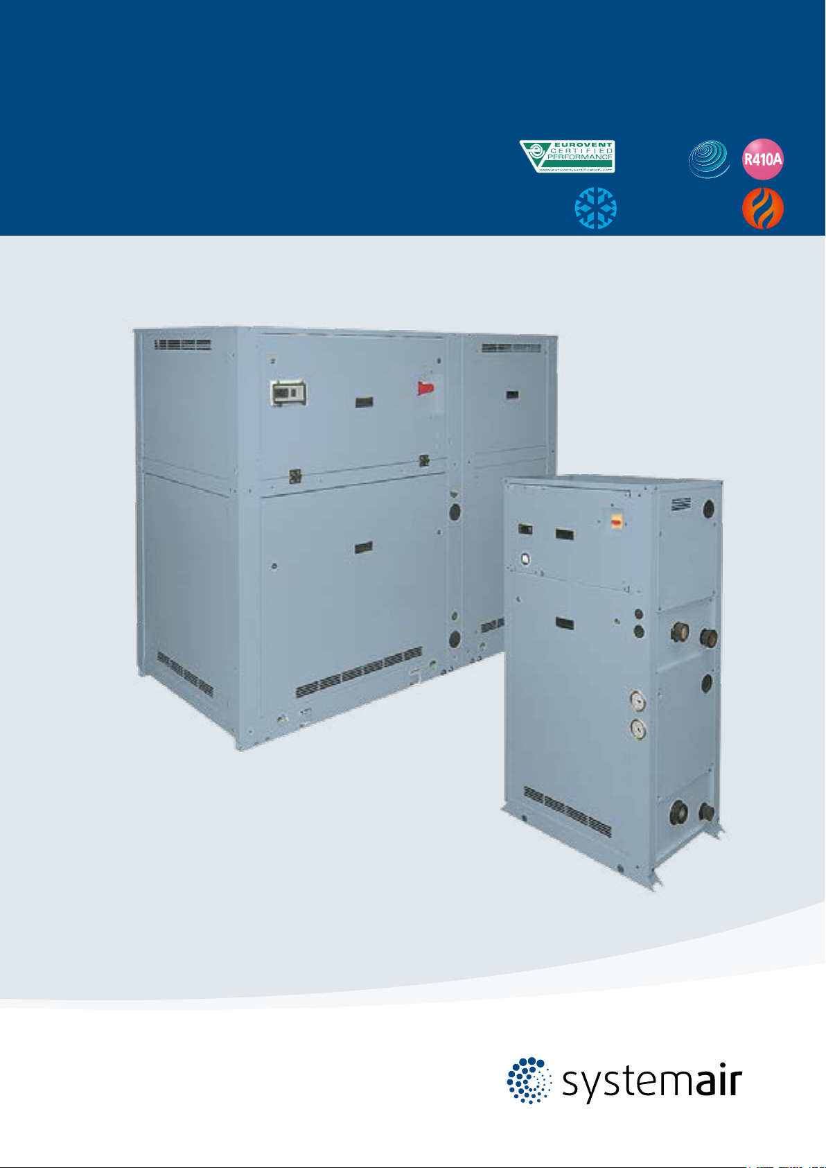
Chiller
WQL/WQH/WQRC 20-190
Water Cooled Water Chillers Cooling Only,
Heat Pump and Condenserless Versions
Engineering Data Manual
21 to 193 kW
24 to 212 kW
Page 2

Page 3
Key point
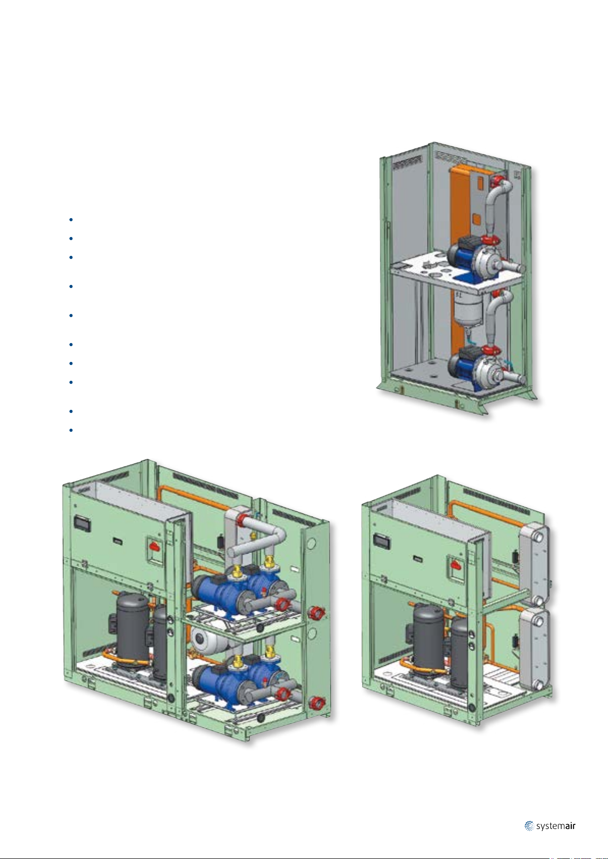
14 sizes from 20 kW up to 190 kW
R410A refrigerant circuit with single or tandem Scroll compressors
2 different frames/configurations : 1 compressor/1 circuit up to 45 kW and
2 compressors/1 circuit from 50 kW to 190 kW
Reduced refrigerant charge (less than 10 kg per circuit for units up to size
90 kW)
New electronic controller with auto-adaptive function to reduce water
content in the piping system
WQL-WQH-WQRC 20-190
|
3
Condensing pressure control available as option for well application
Wide range of hydrokit for "Plug and Play" units
DHW (Domestic Hot Water) function available on the controller with 3-way
valve available as accessory
Victaulic joints for all internal water piping connections
Desuperheater heat exchanger available as option (50-190 sizes)
Sizes from 20 kW to 45 kW
with factory mounted hydrokit
Sizes from 50 kW to 190 kW
with factory mounted hydrokit
Sizes from 50 kW to 190 kW
without hydrokit
Page 4

|
4
WQL-WQH-WQRC 20-190
Specifications
General
WQL/WQH/WQRC are new water to water units equipped with Scroll
compressors, optimized to work with R410A refrigerant.
3 different versions are available :
Cooling only units WQL
Heat pump units WQH
Remote condenser units WQRC
2 different acoustic options are available :
Standard (STD) : units are supplied with compressors box to reduce
noise emissions
Super Low Noise (S) : units are supplied with compressors box and
additional insulation panels on the cabinet in order to furtherly reduce
noise impact
WQL/WQH/WQRC units are available in totally 14 sizes (20, 25, 30, 35, 40,
45, 50, 60, 75, 90, 120, 150, 170, 190), ranging from 20 to 190 kW in
cooling operation and from 25 to 210 kW in heating operation.
WQL/WQH/WQRC units are available on two different structural frames
(F1 for 20-45 sizes, F2 for 50-190 sizes). Each unit is equipped with single
refrigerant circuit, single hermetic scroll compressor for F1 sizes, and two
hermetic scroll compressors (tandem) for F2 sizes.
Evaporators and condensers are brazed plate heat exchanger type.
Heat pump units (WQH) are equipped with reversible valve, thus allowing to
reverse cycle on refrigerant side and not on water side.
Remote condenser units (WQRC) are not equipped with condenser heat
exchangers, but equipped with stop valves on discharge and liquid lines in
order to allow connection to remote condensers.
Cabinet and structure
Cabinet and structure are made of galvanized steel. All galvanized steel
components are individually painted by a special painting process before
assemblying of the unit. This painting system performs a homogeneous
protection to the corrosion. The painting is a polyester powder based type,
coloured in RAL 9001. The units are suitable for indoor installation.
Refrigerant circuit
Refrigerant circuit is equipped with one or two hermetic scroll compressors
(depending on the frame), sight glass, filter-drier and mechanical expansion
valve (electronic expansion valve is available as an option).
Heat pump units (WQH) refrigerant circuit is also provided with 4-way
reversing valve and check valves system in order to always run liquid line in
the same direction (both in cooling and in heating mode).
Remote condenser units (WQRC) refrigerant circuit is supplied without
condenser and it is provided with liquid receiver, stop valves both on
discharge and liquid lines, solenoid valve on liquid line.
The functional diagram of each circuit is shown in section "Refrigerant flow
diagram".
Compressors
Compressors are hermetic scroll type fitted with an electronic control device
ensuring protection of compressors against :
Overheating
Overloading
Reversal rotation
Phase loss
All compressors have direct-on-line starting and are mounted on rubber
vibration isolators in order to minimize noise and vibration transmission.
Evaporators and condensers
Evaporator and condenser heat exchangers are brazed stainless steel plate
type. They are insulated with a 10 mm thick closed cell polyethylene foam
material and provide with Victaulic connections.
Electrical board
Electric equipment is built in compliance with CE standards. Easy accessible
in front of the unit - through an access panel fixed with screws - the equipment
is complete with :
Door lock main isolating switch
Compressor contactors and fuses
Compressor overload protection (optional only on F2 units)
Automatic circuit breaker switches (Standard on F1 units, optional on F2
units)
Phase sequence control
Clamps for remote start/stop switch
Clamps for remote summer/winter switch
Clamps for external flow switches (both exchangers)
Clamps for remote double set-point
Clamps for external interlock
Clamps for remote general alarm
Connection clamps to remote keyboard (optional)
Clamps for evaporator/condenser pump relay control (optional)
Clamps for boiler relay control (optional)
Clamps for dynamic set-point compensation (4-20 mA, 0-1 V, 0-5 V,
0-10 V)
Clamps for DHW 3-way valve (accessory)
Clamps for outdoor air temperature probe (accessory)
Electronic control SBW655
Soft-starter (optional)
Power factor correction capacitors (optional)
0-10 V clamps for condensing control (optional)
Control
A new optimized control is supplied on all the units with a simple user
interface (possibility to customize keys functions and to set menus visibility).
In addition to standard features as water temperature control (with possibility
to choose LWT/EWT probe), the control can also manage following functions :
DHW control with anti-legionella function daily and weekly activated
Dynamic set point (4-20 mA, 0-1V, 0-5V, 0-10V)
Double set point
OAT compensation
Boiler/Electrical heater integration
Condensing control
Auto adaptative function to reduce the water content of the plant
Managing of DHW 3-way valve (accessory)
Advanced pump management (both primary circuit and source side)
Remote keyboard (accessory) with possibility to connect (up to 100 m
distance) without any serial interface
Page 5

WQL-WQH-WQRC 20-190
|
5
Safety
Each unit is equipped with following electrical / refrigerant / hydraulic safety
devices :
Door lock main isolating switch
Phase monitor control
High pressure switch with manual reset
Discharge safety valve
Low pressure switch with automatic / manual reset
Anti-freeze probe (leaving water temperature)
Differential pressure switch (source / plant side)
Standards
WQL/WQH/WQRC are built in compliance with following standards :
Machinery Directive : 2006/42/EC
Low Voltage Directive : 2006/95/EC
Electromagnetic Compatibility Directive : 2014/30/EU
Pressure Equipment Directive : 2014/68/EU
And following harmonized European standards :
Safety of machinery - Basic concepts, general principles for design: UNI
EN ISO 12100-1 / 2
Safety of machinery - Safety Distances To Prevent Hazard Zones Being
Reached By Upper And Lower Limbs : EN ISO 13857
Safety of machinery - Electrical equipment of machines : EN 60204-1
Low-voltage switchgear and controlgear assemblies : EN 60439-1
Electromagnetic compatibility (EMC) - Immunity for industrial
environments : IEC EN 61000-6-2
Electromagnetic compatibility (EMC) - Emission standard for residential,
commercial and light-industrial environments : IEC EN 61000-6-3
Factory installed options
ModBus protocol kit for BMS
Compressor soft starter
Power factor correction capacitors
Electronic expansion valve
Compressor overload protection (only for F2 units)
Automatic circuit breaker (only for F2 units)
Condensing control kit
Electric heater wiring kit
Additional heating device wiring kit
Mechanical gauges kit
Compressor jacket
On board hydrokit (1P/both exchangers/SP for F1 units, 1P/2P/both
exchangers/SP-HP for F2 units)
Desuperheater (only for F2 units)
Field installed accessories
Remote ON-OFF
Remote keyboard panel
Sequencer up to 4 units
Condensing control kit
Water temperature sensor for DHW tank
Outdoor air sensor for weather compensation
Electric heater wiring kit
Additional heating device wiring kit
Pressostatic water valve for well application (only for F1 units)
Compressor jacket
Refrigerating systems and heat pumps. Safety and environmental
requirements : EN 378-1 / 2
Metallic products - Types of inspection documents : EN 10204
Copper and copper alloys. Seamless, round copper tubes for air
conditioning and refrigeration : BS EN 12735-1 / 2
Pressure equipment for refrigerating systems and heat pumps. General
requirements : BS EN 14276-1 / 2
Refrigerating systems and heat pumps - Pressure relief devices and their
associated piping - Methods for calculation : BS EN 13136
Metallic industrial piping : BS EN 13480-3
Flow switch
Pressure switch
Victaulic to threaded pipe connection
3-way valve for DHW production
Spring type anti-vibration mounts (only for F2 units)
Water filter
Valves IN/OUT (only for F1 units)
Page 6

|
1
VALVE (OPTIONAL)
6
WQL-WQH-WQRC 20-190
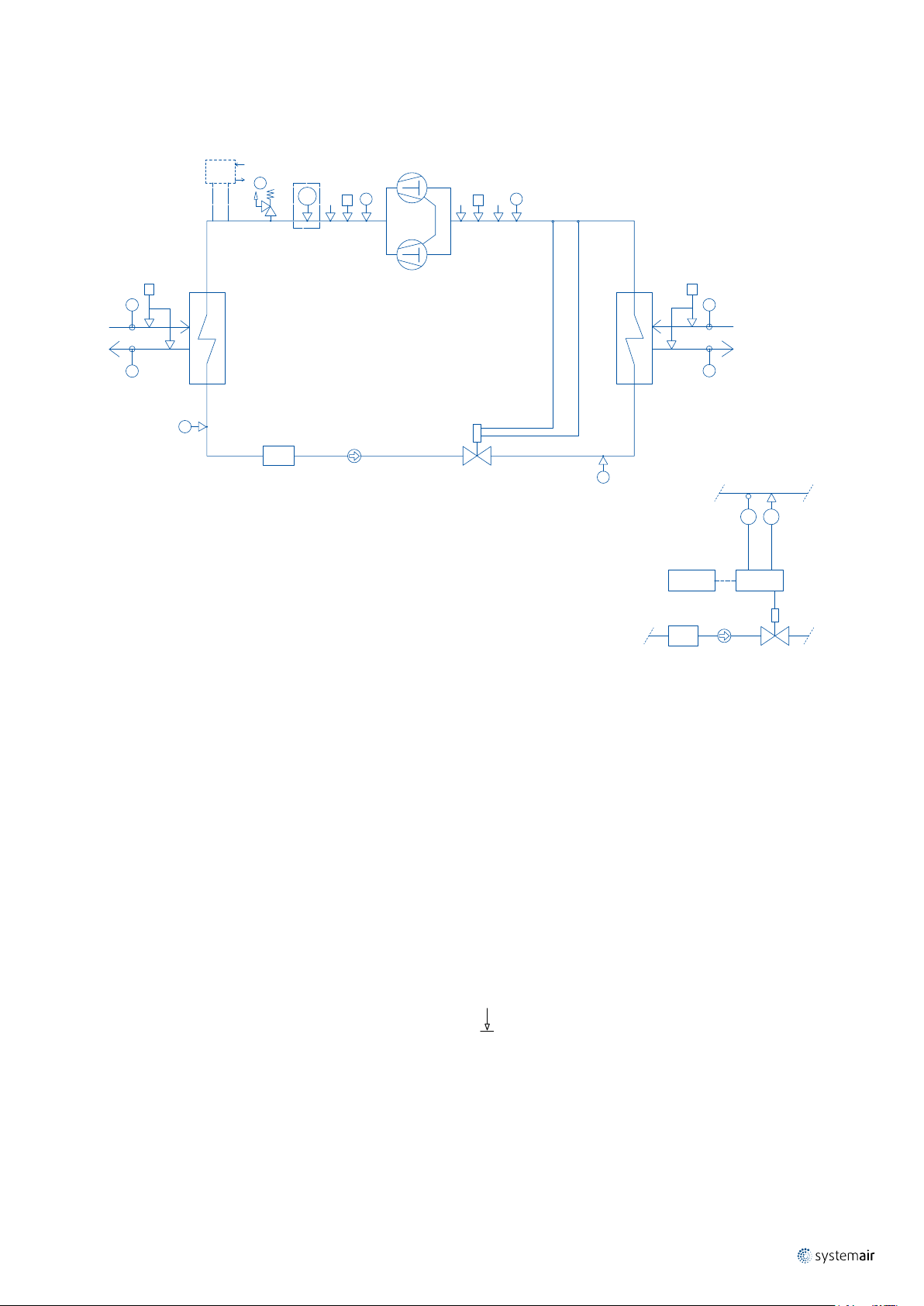
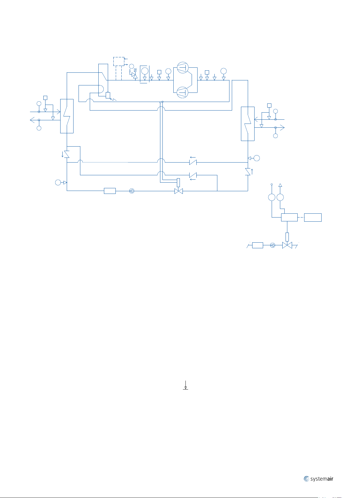
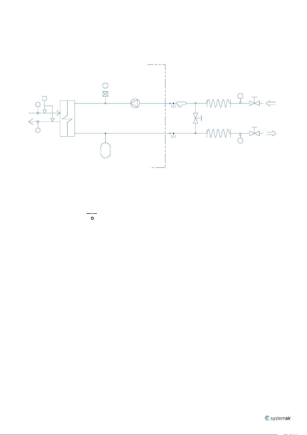
Refrigerant Flow Diagram - WQL 20 to 45
AT
A
2 6
C
F
E
S
S
43
SM
MECHANICAL EXPANSION
VALVE (STANDARD)
B
5
D
G
H
S
UNIT
CONTROL
SUCTION LINE
ST BT
EXV
CONTROL
COMPONENTS
1 Compressor
2 Condenser
3 Drier filter
4 Sight glass
5 Mechanical expansion valve
6 Evaporator
7 Electronic expansion valve
3 4 7
ELECTRONIC EXPANSION
SAFETY / CONTROL DEVICES
A High pressure switch (42 bar)
B Low pressure switch (2 bar)
AT High pressure transducer (optional)
BT Low pressure transducer
C Water differential pressure switch
D Water differential pressure switch
E Outlet water temperature sensor
F Inlet water temperature sensor
G Inlet water temperature sensor
H Outlet water temperature sensor
S 5/16" Shrader connection (service only)
ST Suction temperature probe
Pipe connection with Shrader valve
Page 7
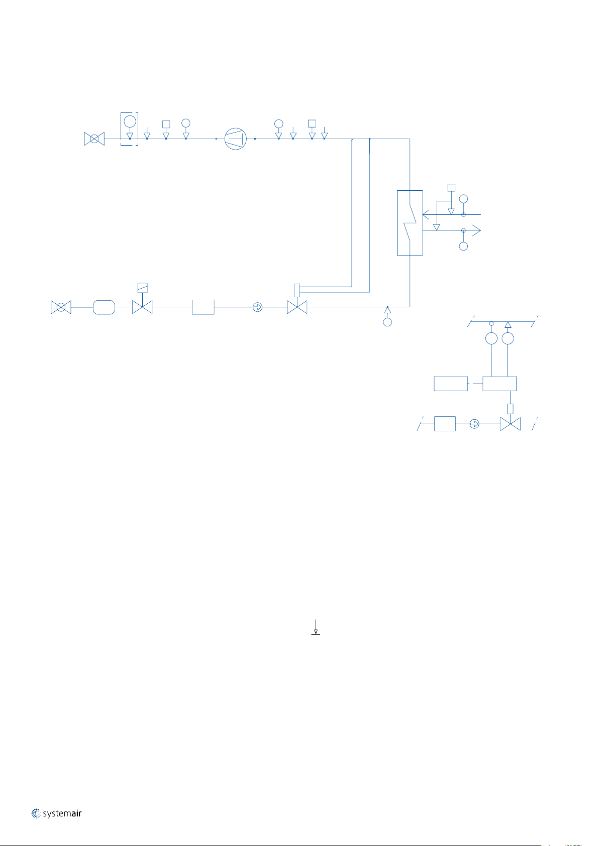
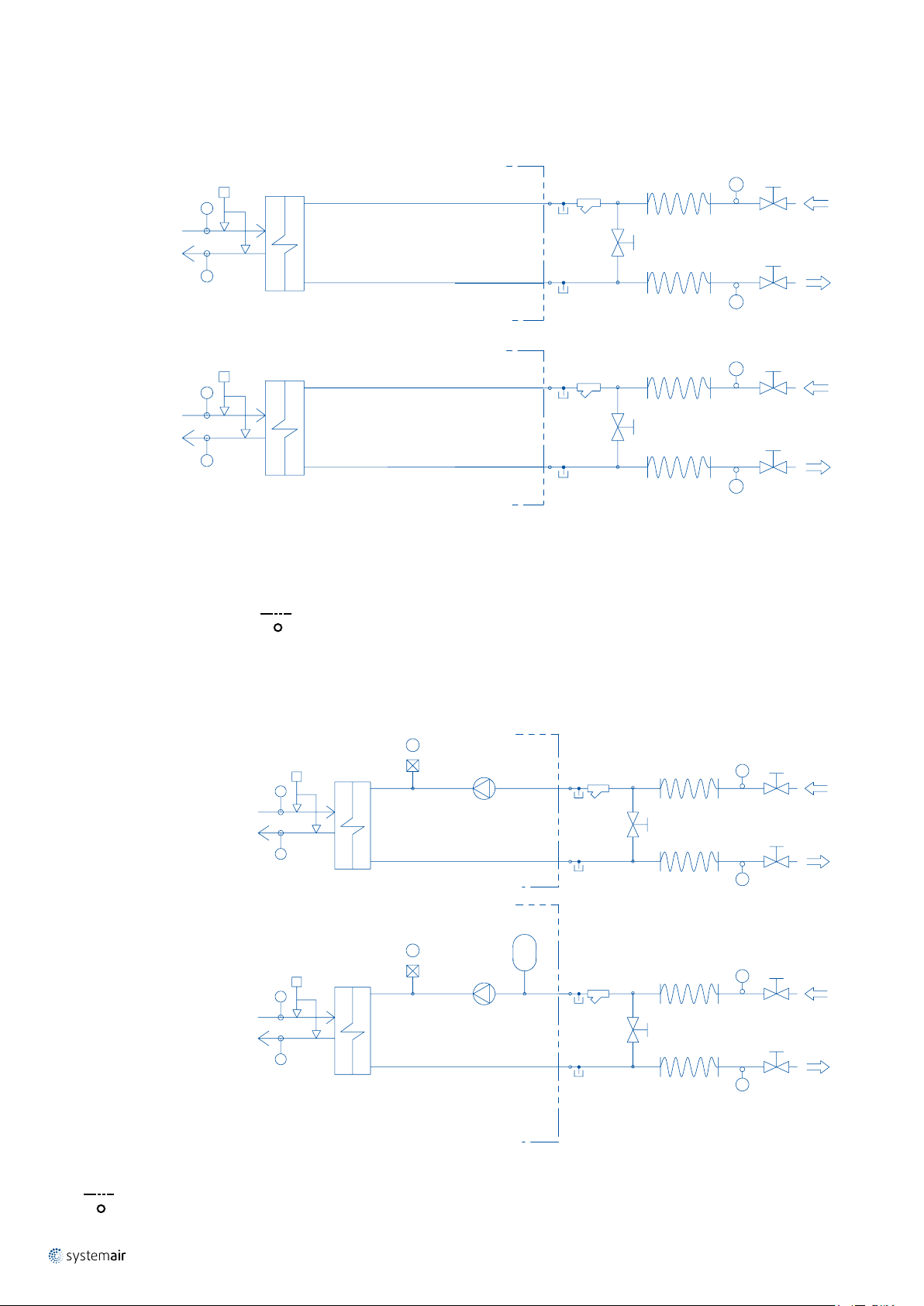
Refrigerant Flow Diagram - WQL 50 to 190
VALVE (OPTIONAL)
WQL-WQH-WQRC 20-190
|
7
8
I
AT
2 6
C
F
E
S
1
S S
A
OIL EQUAL.
43
MECHANICAL EXPANSION
VALVE (STANDARD)
B
D
G
H
5
S
UNIT
CONTROL
SUCTION LINE
ST BT
EXV
CONTROL
COMPONENTS
1 Compressors
2 Condenser
3 Drier filter
4 Sight glass
5 Mechanical expansion valve
6 Evaporator
7 Electronic expansion valve
8 Desuperheater
3 4 7
ELECTRONIC EXPANSION
SAFETY / CONTROL DEVICES
A High pressure switch (40.5 bar)
B Low pressure switch (2 bar)
AT High pressure transducer (optional)
BT Low pressure transducer
C Water differential pressure switch
D Water differential pressure switch
E Outlet water temperature sensor
F Inlet water temperature sensor
G Inlet water temperature sensor
H Outlet water temperature sensor
I PED pressure valve (45 bar)
S 5/16" Shrader connection (service only)
Pipe connection with Shrader valve
Page 8
|
2
VALVE (OPTIONAL)
8
WQL-WQH-WQRC 20-190
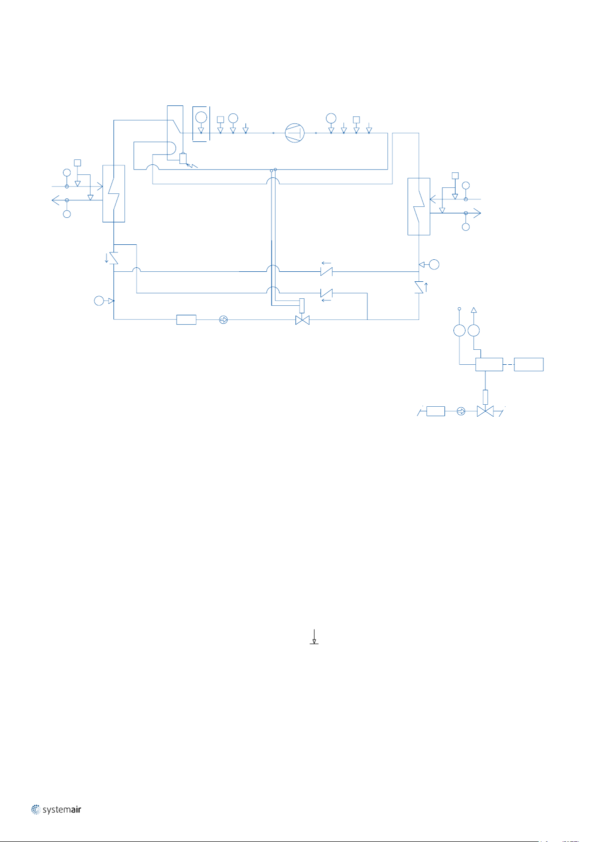
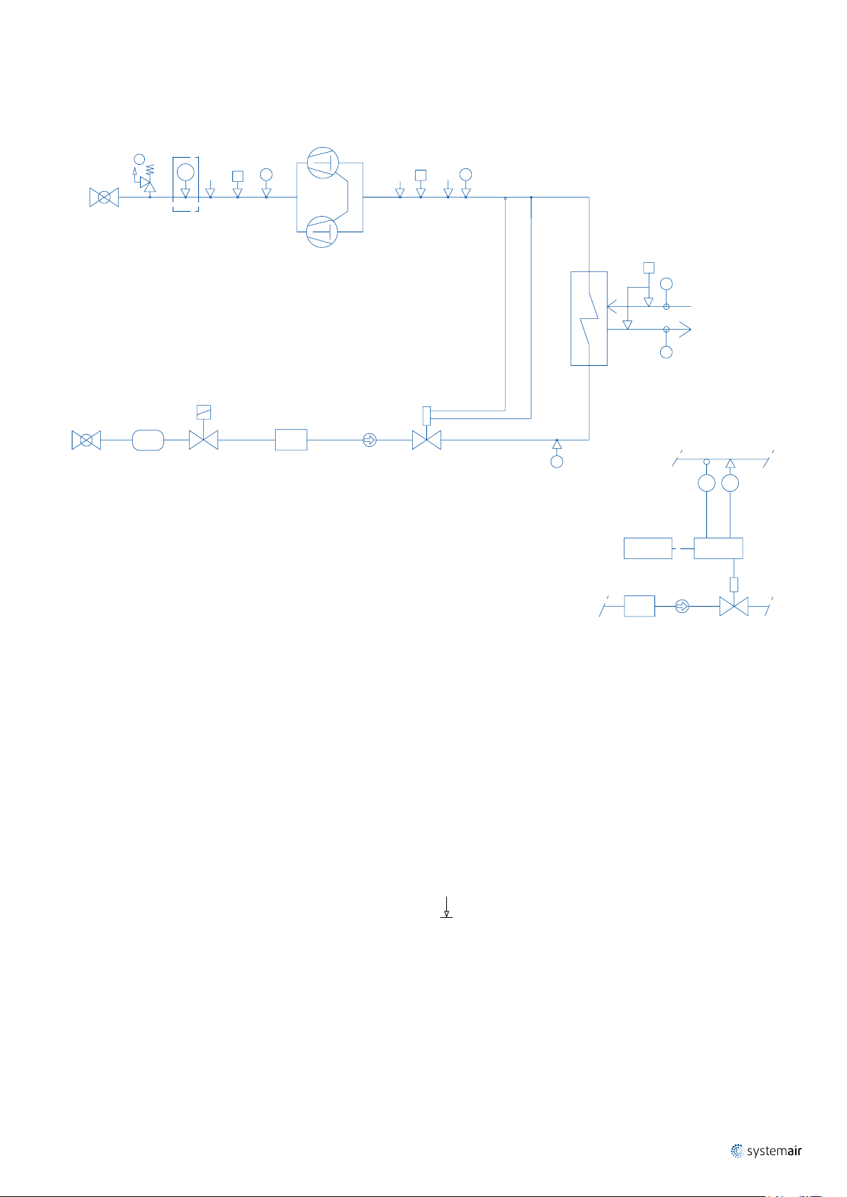
Refrigerant Flow Diagram - WQH 20 to 45
AT
3
C
F
E
S
ON
4
S
A
5
MECHANICAL EXPANSION
1
6
VALVE (STANDARD)
S
B
7
D
G
H
88
8
S
8
ST
BT
EEV
CONTROL
UNIT
CONTROL
COMPONENTS
1 Compressor
2 4-way valve
3 Condenser
4 Drier filter
5 Sight glass
6 Mechanical expansion valve
7 Evaporator
8 Check valve
9 Electronic expansion valve
4
ELECTRONICAL EXPANSION
SAFETY / CONTROL DEVICES
A High pressure switch (42 bar)
B Low pressure switch (2 bar)
AT High pressure transducer (optional)
BT Low pressure transducer
C Water differential pressure switch
D Water differential pressure switch
E Outlet water temperature sensor
F Inlet water temperature sensor
G Inlet water temperature sensor
H Outlet water temperature sensor
S 5/16" Shrader connection (service only)
Pipe connection with Shrader valve
5
9
Page 9
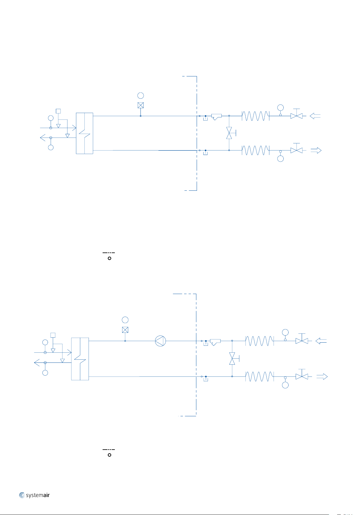
Refrigerant Flow Diagram - WQH 50 to 190
VALVE (OPTIONAL)
2
10
I
AT
1
S
A
OIL EQUAL.
|
WQL-WQH-WQRC 20-190
S
B
9
3
C
F
E
S
ON
7
D
G
H
88
8
4
5
MECHANICAL EXPANSION
6
VALVE (STANDARD)
S
8
ST
BT
EEV
CONTROL
4
5
ELECTRONICAL EXPANSION
9
UNIT
CONTROL
COMPONENTS
1 Compressors
2 4-way valve
3 Condenser
4 Drier filter
5 Sight glass
6 Mechanical expansion valve
7 Evaporator
8 Check valve
9 Electronic expansion valve
10 Desuperheater
SAFETY / CONTROL DEVICES
A High pressure switch (40.5 bar)
B Low pressure switch (2 bar)
AT High pressure transducer (optional)
BT Low pressure transducer
C Water differential pressure switch
D Water differential pressure switch
E Outlet water temperature sensor
F Inlet water temperature sensor
G Inlet water temperature sensor
H Outlet water temperature sensor
I PED pressure relief valve (45 bar)
S 5/16" Shrader connection (service only)
Pipe connection with Shrader valve
Page 10
|
ELECTRONIC EXPANSION
VALVE (OPTIONAL)
10
WQL-WQH-WQRC 20-190
Refrigerant Flow Diagram - WQRC 20 to 45
2
3
AT
4
5
S
A
6
1
7
MECHANICAL EXPANSION
VALVE (STANDARD)
BS
9
8
S
D
UNIT
CONTROL
G
H
SUCTION LINE
ST
BT
EXV
CONTROL
COMPONENTS
1 Compressor
2 Globe valve
3 Globe valve
4 Liquid receiver
5 Solenoid valve
6 Drier filter
7 Sight glass
8 Mechanical expansion valve
9 Evaporator
10 Electronic expansion valve
SAFETY / CONTROL DEVICES
A High pressure switch (42 bar)
B Low pressure switch (2 bar)
AT High pressure transducer (optional)
BT Low pressure transducer
D Water differential pressure switch
G Inlet water temperature sensor
H Outlet water temperature sensor
S 5/16" Shrader connection (service only)
ST Suction temperature probe
Pipe connection with Shrader valve
6
7
10
Page 11
Refrigerant Flow Diagram - WQRC 50 to 190
VALVE (OPTIONAL)
WQL-WQH-WQRC 20-190
|
11
S
1
OIL EQUAL.
6
B
7
MECHANICAL EXPANSION
8
VALVE (STANDARD)
S
9
S
D
UNIT
CONTROL
G
H
SUCTION LINE
ST
BT
EXV
CONTROL
I
2
3
AT
4
A
5
COMPONENTS
1 Compressors
2 Globe valve
3 Globe valve
4 Liquid receiver
5 Solenoid valve
6 Drier filter
7 Sight glass
8 Mechanical expansion valve
9 Evaporator
10 Electronic expansion valve
SAFETY / CONTROL DEVICES
A High pressure switch (40.5 bar)
B Low pressure switch (2 bar)
AT High pressure transducer (optional)
BT Low pressure transducer
D Water differential pressure switch
G Inlet water temperature sensor
H Outlet water temperature sensor
I PED pressure valve (45 bar)
S 5/16" Shrader connection (service only)
ST Suction temperature probe
Pipe connection with Shrader valve
6
7
ELECTRONIC EXPANSION
10
Page 12
|
OUTLET
OUTLET
12
WQL-WQH-WQRC 20-190
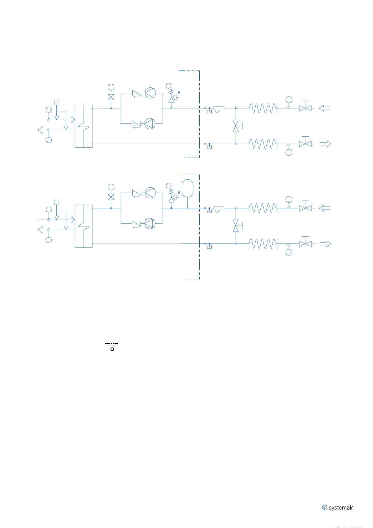
Hydraulic Circuit Diagram - WQL/WQH 20 to 45
Hydraulic system basic
D
A
B
C
1
2
8
8
6
7
6
5
E
4
INLET
5
E
3
COMPONENTS
1 Plate heat exchanger
2 Water filter
3 Water outlet
4 Water inlet
5 Globe valve
6 Flexible pipes
7 By-pass valve
8 Pressure point/drainage
SAFETY / CONTROL DEVICES
A Water differential pressure switch
B Inlet water temperature sensor
C Outlet water temperature sensor
D Vent valve
E Thermometer
Hydraulic system 1P condenser
A
B
C
1
Unit side
Probes
D
2
3
9
9
7
8
7
6
E
5
INLET
6
E
4
COMPONENTS
1 Plate heat exchanger
2 Pump
3 Water filter
4 Water outlet
5 Water inlet
6 Globe valve
7 Flexible pipes
8 By-pass valve
9 Pressure point/drainage
SAFETY / CONTROL DEVICES
A Water differential pressure switch
B Inlet water temperature sensor
C Outlet water temperature sensor
D Vent valve
E Thermometer
Unit side
Probes
Page 13
Hydraulic Circuit Diagram - WQL/WQH 20 to 45 (continued)
OUTLET
Hydraulic system 1P evaporator
D
WQL-WQH-WQRC 20-190
|
13
A
B
C
COMPONENTS
1 Plate heat exchanger
2 Pump
3 Water filter
4 Pressure expansion tank
5 Water outlet
6 Water inlet
7 Globe valve
8 Flexible pipes
9 By-pass valve
10 Pressure point/drainage
1
2
4
SAFETY / CONTROL DEVICES
A Water differential pressure switch
B Inlet water temperature sensor
C Outlet water temperature sensor
D Vent valve
E Thermometer
Unit side
Probes
3
10
10
8
9
8
7
E
6
INLET
7
E
5
Page 14
|
OUTLET
OUTLET
14
WQL-WQH-WQRC 20-190
Hydraulic Circuit Diagram - WQL/WQH 50 to 190
Hydraulic system basic
A
B
C
1- C
2
8
8
6
7
6
5
E
4
INLET
5
3
E
OUTLET
A
B
C
COMPONENTS
1C Condenser
1E Evaporator
2 Water filter
3 Water outlet
4 Water inlet
5 Globe valve
6 Flexible pipes
1- E
SAFETY / CONTROL DEVICES
A Water differential pressure switch
B Inlet water temperature sensor
C Outlet water temperature sensor
D Vent valve
E Thermometer
Unit side
Probes
7 By-pass valve
8 Pressure point/drainage
Hydraulic system 1P condenser and 1P evaporator
D
1- C
D
1- E
COMPONENTS
1C Condenser
1E Evaporator
2 Pump
3 Water filter
4 Pressure expansion tank
5 Water outlet
6 Water inlet
7 Globe valve
8 Flexible pipes
9 By-pass valve
10 Pressure point/drainage
SAFETY / CONTROL DEVICES
A Water differential pressure switch
B Inlet water temperature sensor
C Outlet water temperature sensor
D Vent valve
E Thermometer
Unit side
Probes
A
B
C
A
B
C
2
8
8
2
4
2
3
10
10
3
10
10
6
7
6
8
9
8
8
9
8
5
E
4
INLET
5
E
E
E
E
E
3
7
6
INLET
7
5
7
6
INLET
7
5
OUTLET
Page 15
Hydraulic Circuit Diagram - WQL/WQH 50 to 190 (continued)
OUTLET
OUTLET
Hydraulic system 2P condenser and 2P evaporator
WQL-WQH-WQRC 20-190
|
15
2
D
A
B
C
A
B
C
1- C
D
1- E
10
2
10
2
10
2
10
F
3
11
11
F
4
3
11
11
8
9
8
8
9
8
7
E
6
INLET
7
E
E
E
5
7
6
INLET
7
5
COMPONENTS
1C Condenser
1E Evaporator
2 Pump
3 Water filter
4 Pressure expansion tank
5 Water outlet
6 Water inlet
7 Globe valve
8 Flexible pipes
9 By-pass valve
10 Non-return valve
11 Pressure point/drainage
SAFETY / CONTROL DEVICES
A Water differential pressure switch
B Inlet water temperature sensor
C Outlet water temperature sensor
D Vent valve
E Thermometer
F Water safety valve (6 bar)
Unit side
Probes
Page 16
|
20
25
30
35
40
45
50
55
60
-10 -8 -6 -4 -2 0 2 4 6 8 10 12 14 16 18 20
-10 -8 -6 -4 -2 0 2 4 6 8 10 12 14 16 18 20
25
30
35
40
45
50
55
60
16
WQL-WQH-WQRC 20-190
Operating Limits
WQL/WQH 20 - 190
Chilled
liquid
Leaving water
temperature
Maximum operating pressure bar 6
Heated
liquid
Leaving water
temperature
Maximum operating pressure bar 6
Power supply voltage 400 V, 3 ph, 50 Hz (+/- 10%)
Note : Maximum % glycol (ethylenic or propilenic) : 40%.
Water °C +5 to +18
Brine °C -8 / +5 (with glycol and electronic expansion valve); +5/+18 (standard application)
ΔT water °K 3 to 8
Water °C +25 to +55
ΔT water °K 3 to 15
Water
+
Water
Glycol
Condenser leaving water temperature (°C)Condensing temperature (°C)
Evaporator leaving water temperature (°C)
WQRC 20 - 190
Chilled
liquid
Leaving water
temperature
Maximum operating pressure bar 6
Condensing temperature °C +30 to +58
Power supply voltage 400 V, 3 ph, 50 Hz (+/- 10%)
Note : Maximum % glycol (ethylenic or propilenic) : 40%.
Water °C +5 to +18
Brine °C -8 / +5 (with glycol and electronic expansion valve); +5/+18 (standard application)
Temperature spread °K 3 to 8
Water
+
Glycol
Evaporator leaving water temperature (°C)
Water
Page 17

Correction Factors
Unit capacity, absorbed power, brine flow rate, brine pressure drop, have to be corrected according to following formula :
Corrected unit capacity
x K
i
E,P
c
E,P
i
Q
CORRECTED/GLYCOL
= Q
NOMINAL
x Kc x K
where :
= capacity corrective factor according to LWT (ΔT = 5 [K]) refer to Table 1
K
c
E
= capacity corrective factor according to glycol percentage (ETHYLENE GLYCOL) refer to Table 2
K
c
P
= capacity corrective factor according to glycol percentage (PROPYLENE GLYCOL) refer to Table 4
K
c
Corrected unit absorbed power
P
CORRECTED/GLYCOL
where :
= absorbed power corrective factor according to LWT (ΔT = 5 [K]) refer to Table 1
K
i
E
= absorbed power corrective factor according to glycol percentage (ETHYLENE GLYCOL) refer to Table 2
K
i
P
= absorbed power corrective factor according to glycol percentage (PROPYLENE GLYCOL) refer to Table 4
K
i
= P
NOMINAL
x K
WQL-WQH-WQRC 20-190
|
17
Corrected brine flow rate
G
CORRECTED/GLYCOL
where :
G
RE-CALCULATED
E
= flow rate corrective factor according to glycol percentage (ETHYLENE GLYCOL) refer to Table 2
K
f
K
f
= flow rate according to P
P
= flow rate corrective factor according to glycol percentage (PROPYLENE GLYCOL) refer to Table 4
CORRECTED/GLYCOL
(P
CORRECTED/GLYCOL
= G
RE-CALCULATED
x 860 / ΔT / 3600)
x K
Corrected brine pressure drop
∆P
CORRECTED/GLYCOL
where :
∆P
RE-CALCULATED
E
= pressure drop corrective factor according to glycol percentage (ETHYLENE GLYCOL) refer to Table 2
K
p
P
K
p
Table 1
Leaving water
temperature
[LWT] (°C)
(ΔT=5 [K])
= pressure drop according to G
CORRECTED/GLYCOL
= pressure drop corrective factor according to glycol percentage (PROPYLENE GLYCOL) refer to Table 5
K
c
7 1.000 1.000
4 0.887 0.940
2 0.816 0.900
0 0.748 0.865
-2 0.685 0.826
-4 0.624 0.788
-6 0.568 0.753
-8 0.513 0.718
-10 0.461 0.683
K
i
Table 2
Ethylene Glycol Percentage % 0 10 20 30 35 40
Freezing point (1) °C 0 -4 -10 -17 -21 -25
Minimum leaving water temperature allowed °C 6 2 -2 -6 -8 -8
Capacity corrective factor (2)
Absorbed power corrective factor (2)
Flow rate corrective factor
Pressure drop corrective factor (3)
(1) ASHRAE Handbook Fundamentals.
(2) Valid for LWT=7 °C. If LWT < 7°C consider K
(3) Valid for LWT > 5 °C. If LWT < 5 °C then refer to Table 3.
(K
BPHE
x (G
= ∆P
RE-CALCULATED
CORRECTED/GLYCOL
)2)
x K
E,P
f
E,P
p
E
K
1 0.995 0.985 0.970 0.963 0.955
c
E
K
1 0.998 0.995 0.985 0.983 0.980
i
E
K
1 1.015 1.050 1.085 1.123 1.160
f
E
K
1 1.070 1.160 1.235 1.283 1.330
p
c
x K
E
and Ki x K
c
E
.
i
Page 18

|
18
WQL-WQH-WQRC 20-190
Correction Factors (continued)
Table 3
Ethylene Glycol
Percentage
LWT
(°C)
Corrective factor
E
K
f
5 1.0154 1.0710
10%
4 1.0154 1.0760
3 1.0154 1.0810
2 1.0154 1.0850
1 1.0417 1.1930
20%
0 1.0423 1.2000
-1 1.0428 1.2080
-2 1.0434 1.2150
-3 1.0927 1.2990
30%
-4 1.0936 1.3060
-5 1.0945 1.3200
-6 1.0954 1.3330
Table 4
Propylene Glycol Percentage % 0 10 20 30 40
Freezing point (1) °C 0 -3 -7 -13 -22
P
c
K
x K
c
P
K
i
P
K
f
c
P
and Ki x K
1 0.991 0.977 0.945 0.911
1 0.994 0.991 0.975 0.966
1 1.005 1.030 1.067 1.130
P
.
i
Capacity corrective factor (2)
Absorbed power corrective factor (2)
Flow rate corrective factor
(1) ASHRAE Handbook Fundamentals.
(2) Valid for LWT=7 °C. If LWT < 7°C consider K
Corrective factor
E
K
p
Table 5
Ethylene Glycol
Percentage
10%
20%
30%
40%
LWT
(°C)
Corrective factor
K
5 1.112
4 1.134
5 1.175
4 1.196
3 1.206
5 1.290
4 1.300
3 1.310
0 1.362
-2 1.393
-4 1.414
5 1.433
4 1.435
3 1.456
0 1.497
-2 1.549
-4 1.580
-6 1.612
-8 1.653
P
p
Page 19

Physical Data - WQL 20 to 45
WQL-WQH-WQRC 20-190
|
19
WQL 20 25 30 35 40 45
Cooling Capacity
Input Power
Total EER
2
SEER
2
η
s,c
Number of Refrigerant Circuits
1
1
1
kW
kW
kW/kW
21,2 26,2 31,1 34,8 39,2 46,6
4,56 5,67 6,84 7,54 8,60 10,1
4,67 4,65 4,57 4,64 4,58 4,65
5,58 5,60 5,45 5,50 5,35 5,83
220 221 215 217 211 230
1 1 1 1 1 1
Part Load Steps % 0-100 0-100 0-100 0-100 0-100 0-100
Power Supply 400V/3/50Hz
Startup Type Direct
Maximum Absorbed Power kW 8 10 12 14 15 17
Maximum Corrent (FLA) A 15 21 22 25 31 34
Startup Corrent (LRA) A 101 111 118 118 140 174
REFRIGERANT
Type R410A
Charge kg 2,8 2,8 2,8 2,8 2,9 5,2
COMPRESSOR
Number/Type 1 / Scroll
Crankcase Heater W 70 90 90 90 90 90
EVAPORATOR
Number/Type 1 / Plate
Water Flow Rate l/s 1,02 1,26 1,50 1,68 1,89 2,24
Water Pressure Drop kPa 17,7 26,2 35,6 43,9 40,5 39,7
EVAPORATOR WATER CONNECTIONS
Inlet Diameter - Outlet Diameter / Type inch 1"1/2-1"1/2 / Victaulic
EVAPORATOR PUMP
Input Power kW 1,06 1,06 1,06 1,32 1,32 1,32
Available Static Pressure kPa Refer to pump curves
CONDENSER
Number/Type 1 / Plate
Water Flow Rate l/s 1,23 1,52 1,80 2,02 2,28 2,70
Water Pressure Drop kPa 14,5 21,4 57,4 35,8 44,8 26,5
CONDENSER WATER CONNECTIONS
Inlet Diameter - Outlet Diameter / Type inch 1"1/2-1"1/2 / Victaulic
CONDENSER PUMP
Input Power kW 1,06 1,06 1,32 1,32 1,32 1,32
Available Static Pressure kPa Refer to pump curves
WEIGHT
Shipping Weight kg 156 176 174 179 185 203
Operating Weight kg 162 182 179 185 191 214
DIMENSIONS
Length mm 821 821 821 821 821 821
Width mm 455 455 455 455 455 455
Height mm 1.350 1.350 1.350 1.350 1.350 1.350
ACOUSTIC DATA
Sound Power Level
Sound Pressure Level
Sound Power Level
Sound Pressure Level
3
* dB(A) 65 67 67 68 68 70
4
* dB(A) 34 36 36 37 38 39
3
** dB(A) 62 64 64 65 66 67
4
** dB(A) 31 33 33 34 35 36
1
According to EN14511 standard: Cooling mode conditions: evaporator EWT/LWT 12°C/7°C, condenser EWT/LWT 30°C/35°C.
2
According to EN14825 standard and following COMMISSION REGULATION (EU) No 2016/2281 for comfort application chillers.
3
Sound levels are at fully loaded conditions. Sound power level values refer to ISO 3744 standard.
4
Sound pressure levels calculated at 10m refer to ISO 3744 standard, parallelepiped shape.
* STD version.
** S version.
Page 20

|
20
WQL-WQH-WQRC 20-190
Physical Data - WQH 20 to 45
WQH 20 25 30 35 40 45
Cooling Capacity
Input Power
Total EER
2
SEER
2
η
s,c
Heating Capacity
Input Power
Total COP
SCOP/ η
SCOP/ η
Number of Refrigerant Circuits
1
1
1
kW 20,8 26,0 30,1 34,0 38,1 45,5
kW 4,67 5,82 7,03 7,82 8,80 10,4
kW/kW 4,45 4,47 4,28 4,35 4,34 4,39
5,13 5,00 4,88 5,10 5,00 5,47
3
3
3
4
s,h
5
s,h
kW
kW
kW/kW
202 197 192 201 197 216
23,7 28,9 33,6 38,5 42,9 51,2
6,11 7,51 9,01 10,2 11,4 13,3
3,88 3,85 3,73 3,79 3,77 3,85
5,30/204 5,45/210 5,33/205 5,05/194 4,83/185 5,28/203
4,00/152 4,48/171 4,45/170 4,30/164 4,28/163 4,45/170
1 1 1 1 1 1
Part Load Steps % 0-100 0-100 0-100 0-100 0-100 0-100
Power Supply 400V/3/50Hz
Startup Type Direct
Maximum Absorbed Power kW 8 10 12 14 15 17
Maximum Corrent (FLA) A 15 21 22 25 31 34
Startup Corrent (LRA) A 101 111 118 118 140 174
REFRIGERANT
Type R410A
Charge kg 3,0 3,1 3,1 3,1 3,2 5,5
COMPRESSOR
Number/Type 1 / Scroll
Crankcase Heater W 70 90 90 90 90 90
INTERNAL HEAT EXCHANGER
Number/Type 1 / Plate
Water Flow Rate - Cooling operation l/s 1,00 1,25 1,45 1,63 1,83 2,19
Water Pressure Drop - Cooling operation kPa 17,0 25,6 33,4 41,7 38,3 38,2
Water Flow Rate - Heating operation l/s 1,13 1,38 1,61 1,84 2,05 2,45
Water Pressure Drop - Heating operation kPa 21,8 31,4 41,1 52,8 47,8 47,7
INTERNAL HEAT EXCHANGER WATER CONNECTIONS
Inlet Diameter - Outlet Diameter / Type inch 1"1/2-1"1/2 / Victaulic
INTERNAL HEAT EXCHANGER PUMP
Input Power kW 1,06 1,06 1,06 1,32 1,32 1,32
Available Static Pressure - Cooling operation kPa
Available Static Pressure - Heating operation kPa
Refer to pump curves
EXTERNAL HEAT EXCHANGER
Number/Type 1 / Plate
Water Flow Rate - Cooling operation l/s 1,21 1,51 1,76 1,98 2,23 2,66
Water Pressure Drop - Cooling operation kPa 13,6 20,5 54,8 33,8 42,2 25,5
Water Flow Rate - Heating operation l/s 1,44 1,75 2,03 2,33 2,60 3,11
Water Pressure Drop - Heating operation kPa 19,2 27,4 73,2 46,7 57,1 34,7
EXTERNAL HEAT EXCHANGER WATER CONNECTIONS
Inlet Diameter - Outlet Diameter / Type inch 1"1/2-1"1/2 / Victaulic
EXTERNAL HEAT EXCHANGER PUMP
Input Power
kW 1,06 1,06 1,32 1,32 1,32 1,32
Available Static Pressure kPa Refer to pump curves
WEIGHT
Shipping Weight kg 159 181 179 184 190 208
Operating Weight kg 165 187 184 190 195 219
DIMENSIONS
Length mm 821 821 821 821 821 821
Width mm 455 455 455 455 455 455
Height mm 1.350 1.350 1.350 1.350 1.350 1.350
ACOUSTIC DATA
Sound Power Level
Sound Pressure Level
Sound Power Level
Sound Pressure Level
1
According to EN14511 standard: Cooling mode conditions: evaporator EWT/LWT 12°C/7°C, condenser EWT/LWT 30°C/35°C.
2
According to EN14825 standard and following COMMISSION REGULATION (EU) No 2016/2281 for comfort application chillers.
3
According to EN14511 standard: Heating mode conditions: evaporator EWT/LWT 10°C/7°C, condenser EWT/LWT 40°C/45°C.
4
According to EN14825 standard - low temperature application (35°C) and following COMMISSION REGULATION (EU) No 813/2013 for heat pumps.
5
According to EN14825 standard - medium temperature application (55°C) and following COMMISSION REGULATION (EU) No 813/2013 for heat pumps.
6
Sound levels are at fully loaded conditions. Sound power level values refer to ISO 3744 standard.
7
Sound pressure levels calculated at 10m refer to ISO 3744 standard, parallelepiped shape.
6
* dB(A) 65 67 67 68 68 70
7
* dB(A) 34 36 36 37 38 39
6
** dB(A) 62 64 64 65 66 67
7
** dB(A) 31 33 33 34 35 36
* STD version.
** S version.
Page 21

Physical Data - WQRC 20 to 45
WQL-WQH-WQRC 20-190
|
21
WQRC
Cooling Capacity
Input Power
1
1
Number of Refrigerant Circuits
kW
kW
20 25 30 35 40 45
18,3 22,7 27,1 30 34,2 43,1
5,70 6,97 8,07 9,15 10,1 12,2
1 1 1 1 1 1
Part Load Steps % 0-100 0-100 0-100 0-100 0-100 0-100
Power Supply 400V/3/50Hz
Startup Type Direct
Maximum Absorbed Power kW 8 10 12 14 15 17
Maximum Corrent (FLA) A 15 21 22 25 31 34
Startup Corrent (LRA) A 101 111 118 118 140 174
REFRIGERANT
Type R410A
COMPRESSOR
Number 1 1 1 1 1 1
Type Scroll
Crankcase Heater W 70 90 90 90 90 90
EVAPORATOR
Number 1 1 1 1 1 1
Type Plate
Water Flow Rate l/s 1,00 1,24 1,50 1,66 1,88 2,21
Water Pressure Drop kPa 17,1 25,4 35,6 43,7 34,3 38,9
EVAPORATOR WATER CONNECTIONS
Type Victaulic
Inlet Diameter inch 1"1/2 1"1/2 1"1/2 1"1/2 1"1/2 1"1/2
Outlet Diameter inch 1"1/2 1"1/2 1"1/2 1"1/2 1"1/2 1"1/2
EVAPORATOR PUMP
Number 1 1 1 1 1 1
Input Power kW 1,06 1,06 1,06 1,32 1,32 1,32
Available Static Pressure kPa Refer to pump curves
REMOTE CONDENSER REFRIGERANT CONNECTIONS
Type To be brazed
Inlet Diameter inch 5/8" 5/8" 5/8" 5/8" 5/8" 5/8"
Outlet Diameter inch 5/8" 7/8" 7/8" 7/8" 7/8" 7/8"
WEIGHT
Shipping Weight kg 142 161 163 163 169 168
Operating Weight kg 144 164 166 166 172 172
DIMENSIONS
Length mm 821 821 821 821 821 821
Width mm 455 455 455 455 455 455
Height mm 1.350 1.350 1.350 1.350 1.350 1.350
ACOUSTIC DATA
Sound Power Level
Sound Pressure Level
Sound Power Level
Sound Pressure Level
2
* dB(A) 65 67 67 68 69 70
3
* dB(A) 34 36 36 37 38 39
2
** dB(A) 62 64 64 65 66 67
3
** dB(A) 31 33 33 34 35 36
1
Data referred to evaporator water temperature 12/7°C and condensing temperature 50°C.
2
Sound levels are at fully loaded conditions. Sound power level values refer to ISO 3744 standard.
3
Sound pressure levels calculated at 10m refer to ISO 3744 standard, parallelepiped shape.
* STD version.
** S version.
Page 22

|
22
WQL-WQH-WQRC 20-190
Physical Data - WQL 50 to 190
WQL 50 60 75 90 120 150 170 190
Cooling Capacity
Input Power
Total EER
2
SEER
2
η
s,c
Number of Refrigerant Circuits
1
1
1
kW
50,9 61,1 77,3 91,1 118,4 147,1 170,0 192,7
11,7 13,5 17,1 20,7 26,5 33,0 37,7 42,8
kW
kW/kW 4,35 4,53 4,52 4,40 4,48 4,47 4,51 4,51
6,13 6,38 5,95 6,7 5,90 6,13 6,08 6,2
242 252 235 265 233 242 240 245
1 1 1 1 1 1 1 1
Part Load Steps % 0-50-100 0-50-100 0-50-100 0-50-100 0-50-100 0-50-100 0-50-100 0-50-100
Power Supply 400V/3/50Hz
Startup Type Direct
Maximum Absorbed Power kW 21 25 31 35 48 60 65 71
Maximum Corrent (FLA) A 50 54 66 77 102 130 144 158
Startup Corrent (LRA) A 135 167 191 236 266 325 385 399
REFRIGERANT
Type R410A
Charge kg 4,4 5,7 6,9 8,3 11,3 13,8 15,5 18,1
COMPRESSOR
Number/Type 2 / Scroll
Crankcase Heater W 90+90 90+90 90+90 90+90 120+120 150+150 150+150 150+150
EVAPORATOR
Number/Type 1 / Plate
Water Flow Rate l/s 2,44 2,93 3,71 4,37 5,68 7,05 8,15 9,24
Water Pressure Drop kPa 25,1 20,2 21,4 20,7 21,2 22,6 24,4 25,0
EVAPORATOR WATER CONNECTIONS
Inlet Diameter - Outlet Diameter / Type 2"1/2-2"1/2 / Victaulic
EVAPORATOR PUMP
Input Power/SP kW 1,10 1,10 1,99 1,99 2,45 2,45 3,00 3,00
Available Static Pressure/SP kPa Refer to pump curves
Input Power/HP kW 2,20 2,20 3,26 3,26 3,00 3,00 4,00 4,00
Available Static Pressure/HP kPa Refer to pump curves
CONDENSER
Number/Type 1 / Plate
Water Flow Rate l/s 2,98 3,55 4,50 5,33 6,90 8,57 9,89 11,21
Water Pressure Drop kPa 35,0 27,0 29,0 28,0 29,0 32,0 34,0 35,0
CONDENSER WATER CONNECTIONS
Inlet Diameter - Outlet Diameter / Type 2"1/2-2"1/2 / Victaulic
CONDENSER PUMP
Input Power/SP kW 1,10 1,10 1,99 1,99 2,45 3,00 3,00 4,00
Input Power/HP kW 2,20 2
,20 3,26 3,26 3,00 4,00 5,50 5,50
Available Static Pressure SP / HP kPa Refer to pump curves
DESUPERHEATER
Number/Type 1 / Plate
Heat recovery kW 11,0 14,2 18,1 21,0 25,2 34,1 39,1 41,0
Water flow rate l/s 0,53 0,68 0,86 1,00 1,20 1,63 1,87 1,96
Water pressure drop kPa 8,3 4,5 5,1 5,7 5,0 8,7 10,3 7,5
WEIGHT
Shipping Weight kg 345 361 380 397 578 642 673 713
Operating Weight kg 352 371 392 411 597 666 701 745
DIMENSIONS
Length mm 1.210 1.210 1.210 1.210 1.210 1.210 1.210 1.210
Width mm 850 850 850 850 850 850 850 850
Height mm 1.500 1.500 1.500 1.500 1.500 1.500 1.500 1.500
ACOUSTIC DATA
Sound Power Level
Sound Pressure Level
Sound Power Level
Sound Pressure Level
1
According to EN14511 standard: Cooling mode conditions: evaporator EWT/LWT 12°C/7°C, condenser EWT/LWT 30°C/35°C.
2
According to EN14825 standard and following COMMISSION REGULATION (EU) No 2016/2281 for comfort application chillers.
3
Sound levels are at fully loaded conditions. Sound power level values refer to ISO 3744 standard.
4
Sound pressure levels calculated at 10m refer to ISO 3744 standard, parallelepiped shape.
3
* dB(A) 70 70 72 73 78 81 81 81
4
* dB(A) 39 39 40 42 47 50 50 50
3
** dB(A) 68 68 70 71 76 79 79 79
4
** dB(A) 37 37 39 40 45 48 48 48
* STD version.
** S version.
Page 23

Physical Data - WQH 50 to 190
WQL-WQH-WQRC 20-190
|
23
WQH
Cooling Capacity
Input Power
Total EER
2
SEER
2
η
s,c
Heating Capacity
Input Power
Total COP
SCOP/ η
SCOP/ η
Number of Refrigerant Circuits
1
1
1
3
3
3
4
s,h
5
s,h
kW/kW
kW/kW
50 60 75 90 120 150 170 190
49,9 58,9 76,1 88,6 114,9 144,3 165,7 185,4
kW
12,0 13,9 17,5 21,1 27,0 33,3 38,2 43,3
kW
4,15 4,24 4,36 4,20 4,26 4,34 4,34 4,28
4,70 4,88 4,47 4,83 4,92 4,97 5,65 5,10
185 192 176 190 194 196 223 201
57,7 68,2 86,3 102,2 132,0 164,2 190,1 212,3
kW
15,1 17,9 22,0 26,3 33,7 41,6 48,4 54,0
kW
3,83 3,81 3,92 3,89 3,92 3,95 3,93 3,93
5,70/220 5,88/227 5,70/220 5,78/223 5,75/222 5,63/217 5,95/230 5,63/217
4,63/177 4,78/183 4,75/182 4,75/182 4,73/181 4,48/171 4,88/187 4,68/179
1 1 1 1 1 1 1 1
Part Load Steps % 0-50-100 0-50-100 0-50-100 0-50-100 0-50-100 0-50-100 0-50-100 0-50-100
Power Supply 400V/3/50Hz
Startup Type Direct
Maximum Absorbed Power kW 21 25 31 35 48 60 65 71
Maximum Corrent (FLA) A 50 54 66 77 102 130 144 158
Startup Corrent (LRA) A 135 167 191 236 266 325 385 399
REFRIGERANT
Type R410A
Charge kg 4,7 6,0 7,2 8,6 11,8 14,3 16,0 18,6
COMPRESSOR
Number/Type 2 / Scroll
Crankcase Heater W 90+90 90+90 90+90 90+90 120+120 150+150 150+150 150+150
INTERNAL HEAT EXCHANGER
Number/Type 1 / Plate
Water Flow Rate - Cooling operation l/s 2,40 2,83 3,65 4,25 5,51 6,92 7,95 8,89
Water Pressure Drop - Cooling operation kPa 24,1 18,8 20,7 19,7 20,0 21,8 23,2 23,3
Water Flow Rate - Heating operation l/s 2,73 3,23 4,09 4,84 6,24 7,78 9,00 10,05
Water Pressure Drop - Heating operation kPa 31,3 24,4 26,0 25,5 25,7 27,6 29,8 29,7
INTERNAL HEAT EXCHANGER WATER CONNECTIONS
Inlet Diameter - Outlet Diameter / Type 2"1/2-2"1/2 / Victaulic
INTERNAL HEAT EXCHANGER PUMP
Input Power/SP kW 1,10 1,10 1,99 1,99 2,45 2,45 3,00 3,00
Input Power/HP kW 2,20 2,20 3,26 3,26 3,00 3,00 4,00 4,00
Available Static Pressure SP/HP - Cooling operation kPa
Available Static Pressure SP/HP - Heating operation kPa
Refer to pump curves
EXTERNAL HEAT EXCHANGER
Number/Type 1 / Plate
Water Flow Rate l/s 2,94 3,46 4,45 5,22 6,75 8,45 9,70 10,9
Water Pressure Drop kPa 37,3 28,7 31,2 29,2 29,5 32,1 34,8 34,1
EXTERNAL HEAT EXCHANGER WATER CONNECTIONS
Inlet Diameter - Outlet Diameter / Type 2"1/2-2"1/2 / Victaulic
EXTERNAL HEAT EXCHANGER PUMP
Input Power/SP kW 1,10 1,10 1,99 1,99 2,45 3,00 3,00 4,00
Available Static Pressure/SP kPa Refer to pump curves
Input Power/HP kW 2,20 2,20 3,26 3,26 3,00 4,00 5,50 5,50
Available Static Pressure/HP kPa Refer to pump curves
DESUPERHEATER
Number/Type 1 / Plate
Heat recovery kW 11,0 14,2 18,1 21,0 25,2 34,1 39,1 41,0
Water flow rate l/s 0,53 0,68 0,86 1,00 1,20 1,63 1,87 1,96
Water pressure drop kPa 8,3 4,5 5,1 5,7 5,0 8,7 10,3 7,5
WEIGHT
Shipping Weight kg 353 369 391 408 591 659 691 730
Operating Weight kg 360 379 403 422 610 683 718 762
DIMENSIONS
Length mm 1.210 1.210 1.210 1.210 1.210 1.210 1.210 1.210
Width mm 850 850 850 850 850 850 850 850
Height mm 1.500 1.500 1.500 1.500 1.500 1.500 1.500 1.500
ACOUSTIC DATA
Sound Power Level
Sound Pressure Level
Sound Power Level
Sound Pressure Level
1
According to EN14511 standard: Cooling mode conditions: evaporator EWT/LWT 12°C/7°C, condenser EWT/LWT 30°C/35°C.
2
According to EN14825 standard and following COMMISSION REGULATION (EU) No 2016/2281 for comfort application chillers.
3
According to EN14511 standard: Heating mode conditions: evaporator EWT/LWT 10°C/7°C, condenser EWT/LWT 40°C/45°C.
4
According to EN14825 standard - low temperature application (35°C) and following COMMISSION REGULATION (EU) No 813/2013 for heat pumps.
5
According to EN14825 standard - medium temperature application (55°C) and following COMMISSION REGULATION (EU) No 813/2013 for heat pumps.
6
Sound levels are at fully loaded conditions. Sound power level values refer to ISO 3744 standard.
7
Sound pressure levels calculated at 10m refer to ISO 3744 standard, parallelepiped shape.
6
* dB(A) 70 70 72 73 78 81 81 81
7
* dB(A) 39 39 40 42 47 50 50 50
6
** dB(A) 68 68 70 71 76 79 79 79
7
** dB(A) 37 37 39 40 45 48 48 48
* STD version.
** S version.
Page 24

|
24
WQL-WQH-WQRC 20-190
Physical Data - WQRC 50 to 190
WQRC
Cooling Capacity
Input Power
1
1
Number of Refrigerant Circuits
50 60 75 90 120 150 170 190
45 53,4 67,5 80,1 104 128 148 168
kW
13,7 16 20,1 23,9 30,8 38,1 44,2 49,7
kW
1 1 1 1 1 1 1 1
Part Load Steps % 0-50-100 0-50-100 0-50-100 0-50-100 0-50-100 0-50-100 0-50-100 0-50-100
Power Supply 400V/3/50Hz
Startup Type Direct
Maximum Absorbed Power kW 21 25 31 35 48 60 65 71
Maximum Corrent (FLA) A 50 54 66 77 102 130 144 158
Startup Corrent (LRA) A 135 167 191 236 266 325 385 399
REFRIGERANT
Type R410A
COMPRESSOR
Number 2 2 2 2 2 2 2 2
Type Scroll
Crankcase Heater W 90+90 90+90 90+90 90+90 120+120 150+150 150+150 150+150
EVAPORATOR
Number 1 1 1 1 1 1 1 1
Type Plate
Water Flow Rate l/s 2,45 2,95 3,72 4,37 5,67 7,05 8,09 9,23
Water Pressure Drop kPa 25,2 20,5 21,5 20,7 21,2 22,6 24,1 24,9
EVAPORATOR WATER CONNECTIONS
Type Victaulic
Inlet Diameter inch 2"1/2 2"1/2 2"1/2 2"1/2 2"1/2 2"1/2 2"1/2 2"1/2
Outlet Diameter inch 2"1/2 2"1/2 2"1/2 2"1/2 2"1/2 2"1/2 2"1/2 2"1/2
EVAPORATOR PUMP
Number 1/2 1/2 1/2 1/2 1/2 1/2 1/2 1/2
Input Power/SP kW 1,10 1,10 1,99 1,99 2,45 2,45 3,00 3,00
Available Static Pressure/SP kPa Refer to pump curves
Input Power/HP kW 2,20 2,20 3,26 3,26 3,00 3,00 4,00 4,00
Available Static Pressure/HP kPa Refer to pump curves
REMOTE CONDENSER REFRIGERANT CONNECTIONS
Type To be brazed
Inlet Diameter inch 5/8" 5/8" 7/8" 7/8" 7/8" 7/8" 1 1/8'' 1 1/8''
Outlet Diameter inch 7/8"' 7/8"' 1 1/8'' 1 1/8'' 1 3/8" 1 5/8'' 1 5/8'' 1 5/8''
WEIGHT
Shipping Weight kg 329 339 359 369 548 600 629 658
Operating Weight kg 332 344 365 376 558 612 643 674
DIMENSIONS
Length mm 1.210 1.210 1.210 1.210 1.210 1.210 1.210 1.210
Width mm 850 850 850 850 850 850 850 850
Height mm 1.500 1.500 1.500 1.500 1.500 1.500 1.500 1.500
ACOUSTIC DATA
Sound Power Level
Sound Pressure Level
Sound Power Level
Sound Pressure Level
2
* dB(A) 70 70 72 73 78 81 81 81
3
* dB(A) 39 39 41 42 47 50 50 50
2
** dB(A) 68 68 70 71 76 79 79 79
3
** dB(A) 37 37 39 40 45 48 48 48
1
Data referred to evaporator water temperature 12/7°C and condensing temperature 50°C.
2
Sound levels are at fully loaded conditions. Sound power level values refer to ISO 3744 standard.
3
Sound pressure levels calculated at 10m refer to ISO 3744 standard, parallelepiped shape.
* STD version.
** S version.
Page 25

Electrical Data - WQL/WQH/WQRC 20 to 45
Compressors - 400 V / 3 Ph / 50 Hz
WQL-WQH-WQRC 20-190
|
25
Sizes
20 4.6 9.3 8.3 15 101 0.71 > 0.90
25 5.7 11.8 10.2 21 111 0.70 > 0.90
30 6.5 12.9 12.0 22 118 0.73 > 0.90
35 7.4 13.9 13.5 25 118 0.77 > 0.90
40 8.3 16.0 14.8 31 140 0.75 > 0.90
45 10.1 20.7 17.1 34 174 0.70 > 0.90
(*) Power factor correction capacitor option installed.
Nominal
PNOM-CPS
(kW)
Nominal
INOM-CPS
(A)
Maximum
PMAX-CPS
(kW)
Maximum
IMAX-CPS
(A)
ISTART-CPS
LRA (A)
PF
(NOM)
Standard unit without pump option - 400 V / 3Ph / 50 Hz
Sizes
20 5 8 9 15 101 71
25 6 10 12 21 111 78
30 7 12 13 22 118 83
35 7 14 14 25 118 83
40 8 15 16 31 140 98
45 10 17 21 34 174 122
(*) Soft-starter option installed.
Nominal
power input
(kW)
Maximum
power input
(kW)
Nominal
current input
(A)
Maximum
current input
(A)
Start-up
current (A)
current (A)*
PFC*
Start-up
Pump data - 400 V / 3 Ph / 50 Hz
1PSP/E 1PSP/C
Sizes
20 1.02 1.87 1.02 1.87
25 1.02 1.87 1.02 1.87
30 1.02 1.87 1.32 2.35
35 1.32 2.35 1.32 2.35
40 1.32 2.35 1.32 2.35
45 1.32 2.35 1.32 2.35
MAX-PUMP
P
(kW)
IMAX-PUMP FLA
(A)
PMAX-PUMP
(kW)
IMAX-PUMP FLA
(A)
Page 26

|
26
WQL-WQH-WQRC 20-190
Electrical Data - WQL/WQH/WQRC 50 to 190
Compressors - 400 V / 3 Ph / 50 Hz
Sizes
50
60
75
90
120
150
170
190
(*) Power factor correction capacitor option installed.
Nominal
PNOM-CPS
(kW)
6.1 12.7 10.3 25 110 0.70 > 0.90
6.1 12.7 10.3 25 110 0.70 > 0.90
7.1 15.3 12.7 27 140 0.67 > 0.90
7.1 15.3 12.7 27 140 0.67 > 0.90
8.9 16.6 15.4 33 158 0.78 > 0.90
8.9 16.6 15.4 33 158 0.78 > 0.90
10.4 20.5 17.4 38.6 197 0.74 > 0.90
10.4 20.5 17.4 38.6 197 0.74 > 0.90
13.6 26.7 23.8 51 215 0.74 > 0.90
13.6 26.7 23.8 51 215 0.74 > 0.90
17.9 35.8 30.0 65 260 0.72 > 0.90
17.9 35.8 30.0 65 260 0.72 > 0.90
17.9 35.8 30.0 65 260 0.72 > 0.90
21.0 37.8 35.4 79 320 0.80 > 0.90
21.0 37.8 35.4 79 320 0.80 > 0.90
21.0 37.8 35.4 79 320 0.80 > 0.90
Nominal
INOM-CPS
(A)
Maximum
PMAX-CPS
(kW)
Maximum
IMAX-CPS
(A)
ISTART-CPS
LRA (A)
PF
(NOM)
Standard unit without pump option - 400 V/ 3Ph / 50 Hz
Sizes
50 12 21 25 50 135 102
60 14 25 31 54 167 125
75 18 31 33 66 191 144
90 21 35 41 77 236 177
120 27 48 53 102 266 202
150 36 60 72 130 325 247
170 39 65 74 144 385 289
190 42 71 76 158 399 303
(*) Soft-starter option installed.
Nominal
power input
(kW)
Maximum
power input
(kW)
Nominal
current input
(A)
Maximum
current input
(A)
Start-up
current (A)
PFC*
Start-up
current (A)*
Pump data - 400 V / 3 Ph / 50 Hz
1-2P/SP/E 1-2P/SP/C 1-2P/HP/E 1-2P/HP/C
Sizes
50 1.10 1.96 1.10 1.96 2.20 4.24 2.20 4.24
60 1.10 1.96 1.10 1.96 2.20 4.24 2.20 4.24
75 1.99 3.41 1.99 3.41 3.26 5.86 3.26 5.86
90 1.99 3.41 1.99 3.41 3.26 5.86 3.26 5.86
120 2.45 4.53 2.45 4.53 3.00 6.25 3.00 6.25
150 2.45 4.53 3.00 6.25 3.00 6.25 4.00 7.71
170 3.00 6.25 3.00 6.25 4.00 7.71 5.50 10.40
190 3.00 6.25 4.00 7.71 4.00 7.71 5.50 10.40
MAX-PUMP
P
(kW)
IMAX-PUMP FLA
(A)
PMAX-PUMP
(kW)
IMAX-PUMP FLA
(A)
PMAX-PUMP
(kW)
IMAX-PUMP FLA
(A)
PMAX-PUMP
(kW)
IMAX-PUMP FLA
(A)
Page 27

Sound Data - WQL/WQH/WQRC
WQL/WQH/WQRC 20 to 190 - STD Version
WQL-WQH-WQRC 20-190
|
27
Octave Band (Hz)
Sizes
20 59 61 64 63 61 56 54 44 65 34
25 61 63 66 65 63 58 56 46 67 36
30 61 63 66 65 63 58 56 46 67 36
35 62 64 67 66 64 59 57 47 68 37
40 63 65 68 67 65 60 58 48 69 38
45 64 66 69 68 66 61 59 49 70 39
50 63 66 68 68 66 61 59 49 70 39
60 63 66 68 68 66 61 59 49 70 39
75 65 68 70 70 68 63 61 51 72 41
90 66 69 71 71 69 64 62 52 73 42
120 71 74 76 76 74 69 67 57 78 47
150 74 77 79 79 77 72 70 60 81 50
170 74 77 79 79 77 72 70 60 81 50
190 74 77 79 79 77 72 70 60 81 50
(*) Sound pressure levels are given at 10 meters distance according to ISO standard 3744 with parallepiped shape.
63 125 250 500 1000 2000 4000 8000
Sound Power Level dB
Sound Power
dB(A)
WQL/WQH/WQRC 20 to 190 - S Version
Octave Band (Hz)
Sizes
20 56 58 61 60 58 53 51 41 62 31
25 58 60 63 62 60 55 53 43 64 33
30 58 60 63 62 60 55 53 43 64 33
35 59 61 64 63 61 56 54 44 65 34
40 60 62 65 64 62 57 55 45 66 35
45 61 63 66 65 63 58 56 46 67 36
50 61 64 66 66 64 59 57 47 68 37
60 61 64 66 66 64 59 57 47 68 37
75 63 66 68 68 66 61 59 49 70 39
90 64 67 69 69 67 62 60 50 71 40
120 69 72 74 74 72 67 65 55 76 45
150 72 75 77 77 75 70 68 58 79 48
170 72 75 77 77 75 70 68 58 79 48
190 72 75 77 77 75 70 68 58 79 48
(*) Sound pressure levels are given at 10 meters distance according to ISO standard 3744 with parallepiped shape.
63 125 250 500 1000 2000 4000 8000
Sound Power Level dB
Sound Power
dB(A)
Sound Pressure
dB(A)*
Sound Pressure
dB(A)*
Page 28

|
28
WQL-WQH-WQRC 20-190
Performance Data - WQL 20 to 45
Cooling Capacities - CO Mode
WQL
models
WQL
20
WQL
25
WQL
30
Evap.
LWT
(°C)
5 22.0 3.53 21.0 3.89 19.8 4.34 18.5 4.92 17.0 5.65 15.5 6.54 14.6 7.10
6 22.9 3.60 21.7 3.96 20.5 4.39 19.3 4.91 18.0 5.54 16.7 6.28 16.2 6.65
7 23.8 3.65 22.5 3.97 21.3 4.43 19.8 4.80 18.7 5.51 17.3 6.32 16.9 6.40
8 24.7 3.68 23.4 4.03 22.1 4.44 20.8 4.94 19.4 5.52 18.0 6.17 17.5 6.45
9 25.6 3.71 24.3 4.04 22.9 4.45 21.6 4.96 20.2 5.60 18.7 6.34 18.2 6.72
10 26.5 3.73 25.2 4.06 23.8 4.46 22.1 5.01 20.3 5.69 18.4 6.52 17.3 6.99
11 27.3 3.80 26.0 4.10 24.7 4.50 23.2 5.06 21.8 5.77 20.2 6.64 19.7 7.15
12 28.1 3.87 26.8 4.18 25.5 4.56 24.1 5.11 22.6 5.82 21.0 6.68 20.4 7.19
13 28.8 3.98 27.6 4.26 26.3 4.64 24.9 5.16 23.4 5.83 21.7 6.67 21.1 7.14
14 29.5 4.10 28.4 4.36 27.2 4.71 25.7 5.19 24.2 5.83 22.5 6.63 21.8 7.05
15 30.2 4.23 29.2 4.45 28.0 4.76 26.2 5.20 24.2 5.81 21.9 6.56 20.6 6.95
16 30.8 4.36 29.9 4.53 28.8 4.78 27.4 5.18 25.7 5.76 24.0 6.50 23.3 6.89
17 31.5 4.48 30.7 4.59 29.6 4.77 28.2 5.13 26.5 5.69 24.7 6.44 24.0 6.85
18 32.3 4.61 31.6 4.64 30.3 4.76 28.5 5.09 26.1 5.63 23.5 6.37 21.9 6.82
5 27.4 4.43 26.1 4.85 24.6 5.37 22.9 6.06 21.1 6.93 19.2 7.97 18.3 8.58
6 28.5 4.50 27.0 4.92 25.5 5.43 23.9 6.05 22.3 6.78 20.7 7.64 20.2 8.02
7 29.7 4.56 28.0 4.93 26.4 5.48 24.5 5.92 23.1 6.74 21.5 7.69 21.2 7.70
8 30.9 4.60 29.1 5.02 27.4 5.50 25.7 6.08 24.0 6.75 22.4 7.50 21.9 7.77
9 32.0 4.61 30.2 5.02 28.4 5.51 26.7 6.11 24.9 6.84 23.2 7.70 22.7 8.08
10 33.1 4.65 31.4 5.05 29.4 5.53 27.3 6.17 25.0 6.97 22.7 7.92 21.6 8.41
11 34.2 4.71 32.3 5.11 30.5 5.59 28.7 6.23 26.8 7.07 24.9 8.07 24.4 8.60
12 35.1 4.81 33.4 5.20 31.6 5.68 29.7 6.32 27.8 7.13 25.7 8.13 25.2 8.65
13 36.0 4.95 34.4 5.31 32.6 5.76 30.7 6.38 28.7 7.17
14 36.8 5.09 35.4 5.44 33.7 5.86 31.8 6.43 29.6 7.18 27.2 8.08 26.5 8.51
15 37.7 5.25 36.5 5.55 34.7 5.92 32.4 6.46 29.5 7.16 26.3 8.03 24.7 8.43
16 38.5 5.40 37.3 5.64 35.8 5.96 33.8 6.44 31.4 7.12 28.5 7.96 27.6 8.37
17 39.3 5.57 38.4 5.74 36.9 5.97 34.8 6.41 32.2 7.06 29.0 7.91 28.0 8.35
18 40.3 5.72 39.6 5.81 38.0 5.97 35.3 6.36 31.6 7.01 27.2 7.86 25.1 8.35
5 32.4 5.15 30.9 5.66 29.2 6.32 27.1 7.18 24.7 8.27 22.2 9.59 21.6 10.0
6 33.6 5.24 32.0 5.76 30.2 6.39 28.3 7.17 26.2 8.10 24.0 9.19 23.8 9.37
7 34.9 5.30 33.1 5.76 31.3 6.44 28.9 7.00 27.1 8.05 24.8 9.24 24.9 8.99
8 36.2 5.33 34.4 5.85 32.4 6.46 30.4 7.19 28.2 8.03 25.8 9.00 25.8 9.06
9 37.5 5.36 35.6 5.85 33.6 6.45 31.5 7.21 29.3 8.14 26.8 9.23 26.8 9.40
10 38.7 5.40 37.0 5.86 34.8 6.46 32.3 7.26 29.4 8.27 26.3 9.49 25.5 9.77
11 39.9 5.47 38.1 5.93 36.0 6.53 33.9 7.33 31.5 8.37 28.9 9.63 29.0 9.97
12 40.9 5.60 39.2 6.03 37.2 6.60 35.1 7.40 32.7 8.42 30.0 9.66 30.0 10.0
13 41.9 5.75 40.3 6.15 38.4 6.70 36.3 7.45 33.8 8.44 31.1 9.61 31.0 9.96
14 42.7 5.91 41.3 6.28 39.6 6.78 37.4 7.49 34.9 8.41 32.2 9.51 32.0 9.84
15 43.5 6.09 42.4 6.41 40.7 6.84 38.1 7.48 34.9 8.36 31.4 9.38 30.1 9.71
16 44.4 6.28 43.3 6.51 41.8 6.86 39.7 7.44 37.2 8.27 34.4 9.25 33.9 9.61
17 45.2 6.45 44.3 6.59 42.9 6.84 40.9 7.36 38.3 8.15 35.6 9.12 34.9 9.56
18 46.2 6.62 45.5 6.66 44.0 6.82 41.3 7.27 37.7 8.04 33.8 9.00 31.7 9.52
25 30 35 40 45 50 55
Cooling
(kW)
cap.
Input
power
(kW)
Cooling
cap.
(kW)
power
Input
(kW)
Cooling
cap.
(kW)
Condenser LWT (°C)
Input
Cooling
power
(kW)
cap.
(kW)
Input
power
(kW)
Cooling
cap.
(kW)
Input
power
(kW)
Cooling
cap.
(kW)
26.5 8.12 25.9 8.61
Input
power
(kW)
Cooling
cap.
(kW)
Input
power
(kW)
Page 29

Performance Data - WQL 20 to 45 (continued)
Cooling Capacities - CO Mode
Condenser LWT (°C)
WQL
models
WQL
35
WQL
40
WQL
45
Evap.
LWT
(°C)
5 36.3 5.83 34.7 6.35 32.7 7.04 30.4 7.97 27.7 9.18 24.8 10.7 23.6 11.4
6 37.7 5.94 35.9 6.45 33.9 7.11 31.7 7.96 29.3 8.99 26.7 10.2 26.1 10.6
7 39.1 6.02 37.1 6.46 35.1 7.17 32.4 7.77 30.3 8.93 27.7 10.3 27.3 10.2
8 40.6 6.06 38.6 6.56 36.3 7.18 34.0 7.97 31.5 8.91 28.8 10.02 28.2 10.3
9 42.1 6.09 40.0 6.56 37.7 7.18 35.3 8.00 32.7 9.03 29.9 10.3 29.4 10.7
10 43.5 6.13 41.5 6.57 39.0 7.19 36.1 8.05 32.9 9.17 29.3 10.6 28.0 11.1
11 44.9 6.22 42.7 6.64 40.4 7.25 37.9 8.12 35.2 9.28 32.3 10.7 31.7 11.3
12 46.1 6.34 44.0 6.75 41.7 7.34 39.2 8.19 36.5 9.34 33.4 10.8 32.9 11.4
13 47.2 6.51 45.3 6.88 43.1 7.43 40.6 8.25 37.7 9.36 34.6 10.8 34.1 11.3
14 48.3 6.70 46.5 7.02 44.4 7.52 41.9 8.28 39.0 9.34 35.8 10.7 35.2 11.1
15 49.4 6.90 47.9 7.14 45.7 7.57 42.7 8.27 39.0 9.28 34.8 10.6 33.2 11.0
16 50.4 7.10 48.9 7.25 47.0 7.59 44.5 8.22 41.5 9.17 38.1 10.4 37.6 10.9
17 51.5 7.31 50.2 7.33 48.3 7.56 45.8 8.13 42.7 9.05 39.3 10.3 38.7 10.8
18 52.7 7.49 51.6 7.40 49.6 7.52 46.3 8.03 42.1 8.93 37.3 10.2 35.3 10.7
5 40.5 6.74 38.9 7.27 36.8 7.97 34.3 8.96 31.3 10.3 28.0 11.8 26.9 12.5
6 42.1 6.88 40.2 7.40 38.1 8.08 35.8 8.96 33.2 10.1 30.3 11.4 29.8 11.8
7 43.7 7.00 41.7 7.43 39.5 8.16 36.6 8.77 34.3 10.0 31.3 11.5 31.1 11.3
8 45.4 7.08 43.3 7.55 40.9 8.19 38.4 9.00 35.7 10.0 32.7 11.2 32.2 11.4
9 47.1 7.13 44.9 7.57 42.4 8.20 39.8 9.06 37.0 10.2 34.0 11.5 33.5 11.9
10 48.7 7.22 46.6 7.62 44.0 8.24 40.8 9.14 37.2 10.3 33.3 11.8 32.0 12.4
11 50.2 7.35 48.0 7.72 45.5 8.32 42.8 9.23 39.9 10.5 36.6 12.1 36.3 12.6
12 51.6 7.53 49.5 7.87 47.0 8.44 44.3 9.32 41.3 10.5 38.0 12.1 37.7 12.7
13 52.9 7.76 50.9 8.05 48.5 8.58 45.8 9.41 42.8 10.6
14 54.1 8.01 52.3 8.24 50.0 8.70 47.3 9.47 44.3 10.6 40.8 12.0 40.4 12.4
15 55.3 8.29 53.8 8.42 51.5 8.78 48.3 9.46 44.2 10.5 39.7 11.8 38.2 12.2
16 56.5 8.57 54.9 8.57 53.0 8.82 50.3 9.41 47.2 10.4 43.5 11.7 43.2 12.1
17 57.7 8.85 56.4 8.70 54.4 8.81 51.8 9.31 48.6 10.2 44.9 11.5 44.6 12.0
18 59.1 9.11 58.0 8.81 55.9 8.78 52.4 9.20 47.8 10.1 42.7 11.4 40.6 11.8
5 48.6 7.73 46.0 8.53 43.8 9.47 41.8 10.6 40.0 12.0 38.7 13.6 37.8 14.6
6 50.4 7.80 47.6 8.65 45.3 9.58 43.6 10.6 42.4 11.8 41.8 13.1 41.7 13.7
7 52.4 7.83 49.3 8.63 46.9 9.65 44.5 10.4 43.8 11.7 43.1 13.2 43.5 13.2
8 54.4 7.82 51.2 8.72 48.7 9.67 46.8 10.7 45.5 11.8 44.9 12.9 44.9 13.3
9 56.3 7.78 53.1 8.68 50.4 9.65 48.5 10.7 47.2 11.9 46.6 13.2 46.6 13.9
10 58.2 7.75 55.1 8.67 52.3 9.65 49.7 10.8 47.4 12.1 45.6 13.7 44.3 14.5
11 60.0 7.76 56.7 8.70 54.1 9.71 52.1 10.9 50.8 12.3 50.1 13.9 50.1 14.8
12 61.6 7.83 58.4 8.78 55.9 9.79 53.9 11.0 52.6 12.4 51.9 14.0 51.9 14.9
13 63.1 7.91 60.1 8.87 57.6 9.9 55.7 11.1 54.4 12.5 53.7 14.0 53.6 14.8
14 64.5 8.02 61.7 8.98 59.4 10.0 57.5 11.1 56.2 12.4 55.5 13.9 55.4 14.7
15 65.8 8.14 63.4 9.05 61.1 10.0 58.6 11.1 56.1 12.4 53.9 13.8 52.1 14.5
16 67.2 8.24 64.8 9.09 62.8 9.9 61.1 11.0 59.8 12.3 59.0 13.7 58.8 14.4
17 68.6 8.31 66.4 9.08 64.5 9.8 62.8 10.8 61.5 12.1 60.8 13.6 60.5 14.4
18 70.2 8.36 68.3 9.05 66.1 9.7 63.5 10.6 60.5 11.9 57.7 13.5 55.1 14.4
25 30 35 40 45 50 55
Cooling
(kW)
cap.
Input
power
(kW)
Cooling
cap.
(kW)
Input
power
(kW)
Cooling
cap.
(kW)
Input
power
(kW)
Cooling
cap.
(kW)
Input
power
(kW)
Cooling
cap.
(kW)
Input
power
(kW)
WQL-WQH-WQRC 20-190
Cooling
cap.
(kW)
39.4 12.1 39.1 12.6
Input
power
(kW)
Cooling
cap.
(kW)
Input
power
(kW)
|
29
Page 30

|
30
WQL-WQH-WQRC 20-190
Performance Data - WQH 20 to 45
Cooling capacities
WQH
models
WQH
20
WQH
25
WQH
30
Evap.
LWT
(°C)
5 21.5 3.60 20.5 3.95 19.4 4.39 18.1 4.96 16.7 5.68 15.2 6.57 14.4 7.12
6 22.4 3.68 21.3 4.03 20.1 4.44 18.9 4.96 17.7 5.59 16.4 6.31 15.9 6.68
7 23.2 3.73 22.0 4.04 20.9 4.49 19.4 4.86 18.3 5.55 17.0 6.36 16.6 6.42
8 24.1 3.77 22.9 4.10 21.6 4.51 20.4 4.98 19.0 5.56 17.7 6.20 17.2 6.48
9 25.0 3.79 23.8 4.12 22.5 4.51 21.1 5.02 19.8 5.64 18.4 6.38 17.8 6.75
10 25.9 3.82 24.7 4.13 23.3 4.53 21.7 5.06 19.9 5.74 18.0 6.56 17.0 7.03
11 26.7 3.89 25.4 4.19 24.1 4.58 22.8 5.11 21.3 5.82 19.8 6.69 19.3 7.19
12 27.4 3.98 26.2 4.27 24.9 4.65 23.6 5.18 22.1 5.88 20.5 6.73 20.0 7.23
13 28.1 4.10 27.0 4.36 25.7 4.72 24.4 5.23 22.9 5.90 21.3 6.72 20.7 7.19
14 28.7 4.22 27.7 4.46 26.5 4.79 25.2 5.27 23.7 5.90 22.0 6.67 21.4 7.11
15 29.4 4.36 28.5 4.56 27.3 4.85 25.6 5.28 23.6 5.87 21.4 6.62 20.2 7.01
16 30.0 4.49 29.2 4.65 28.1 4.86 26.7 5.26 25.2 5.82 23.4 6.56 22.8 6.95
17 30.7 4.64 29.9 4.71 28.8 4.87 27.5 5.22 25.9 5.76 24.1 6.49 23.5 6.91
18 31.4 4.77 30.8 4.77 29.6 4.87 27.8 5.17 25.5 5.70 22.9 6.43 21.4 6.89
5 27.1 4.46 25.8 4.88 24.3 5.41 22.7 6.11 20.9 6.98 19.0 8.03 18.0 8.64
6 28.2 4.53 26.7 4.96 25.2 5.47 23.7 6.10 22.1 6.83 20.5 7.69 20.0 8.08
7 29.3 4.59 27.7 4.97 26.1 5.52 24.2 5.96 22.8 6.79 21.2 7.75 20.9 7.76
8 30.5 4.63 28.8 5.05 27.1 5.54 25.4 6.12 23.8 6.80 22.1 7.56 21.6 7.82
9 31.7 4.65 29.9 5.06 28.1 5.55 26.4 6.16 24.7 6.89 23.0 7.76 22.5 8.14
10 32.8 4.69 31.0 5.08 29.1 5.57 27.0 6.22 24.8 7.02 22.5 7.98 21.3 8.47
11 33.8 4.75 32.0 5.14 30.2 5.63 28.3 6.28 26.5 7.12 24.6 8.13 24.1 8.67
12 34.7 4.85 33.0 5.23 31.2 5.72 29.4 6.36 27.4 7.19 25.4 8.19 24.9 8.71
13 35.6 4.99 34.0 5.35 32.3 5.80 30.4 6.42 28.4 7.22
14 36.4 5.13 35.0 5.48 33.3 5.90 31.4 6.48 29.3 7.23 26.9 8.14 26.2 8.57
15 37.2 5.29 36.0 5.59 34.4 5.97 32.0 6.50 29.2 7.21 26.0 8.08 24.5 8.49
16 38.1 5.44 36.9 5.68 35.4 6.00 33.4 6.49 31.0 7.17 28.2 8.02 27.3 8.43
17 38.9 5.61 37.9 5.78 36.5 6.02 34.4 6.46 31.9 7.11 28.7 7.97 27.7 8.41
18 39.8 5.76 39.1 5.85 37.6 6.02 34.9 6.41 31.2 7.06 26.9 7.92 24.8 8.41
5 31.4 5.23 30.0 5.75 28.2 6.39 26.2 7.25 23.9 8.34 21.4 9.66 20.8 10.1
6 32.6 5.32 31.0 5.84 29.2 6.47 27.4 7.24 25.3 8.17 23.1 9.25 23.0 9.44
7 33.9 5.39 32.1 5.85 30.3 6.52 28.0 7.08 26.2 8.12 23.9 9.31 24.0 9.07
8 35.1 5.44 33.3 5.93 31.4 6.53 29.4 7.25 27.2 8.11 24.9 9.08 24.8 9.13
9 36.4 5.46 34.5 5.94 32.6 6.54 30.5 7.29 28.2 8.22 25.9 9.31 25.8 9.48
10 37.6 5.50 35.8 5.97 33.7 6.56 31.2 7.35 28.4 8.34 25.3 9.56 24.6 9.86
11 38.7 5.58 36.9 6.02 34.9 6.61 32.7 7.42 30.4 8.45 27.9 9.71 27.9 10.1
12 39.7 5.70 38.0 6.14 36.0 6.70 33.9 7.49 31.5 8.51 28.9 9.75 28.9 10.1
13 40.6 5.86 39.0 6.26 37.2 6.80 35.0 7.55 32.6 8.52 30.0 9.70 29.8 10.0
14 41.4 6.03 40.0 6.39 38.3 6.88 36.2 7.58 33.7 8.51 31.0 9.60 30.8 9.92
15 42.3 6.22 41.1 6.52 39.4 6.95 36.8 7.58 33.7 8.45 30.2 9.48 29.0 9.78
16 43.1 6.42 42.0 6.63 40.5 6.97 38.4 7.54 35.9 8.36 33.1 9.34 32.7 9.70
17 43.9 6.61 43.0 6.72 41.5 6.96 39.5 7.46 36.9 8.24 34.2 9.22 33.6 9.64
18 44.9 6.78 44.1 6.79 42.6 6.93 39.9 7.36 36.3 8.13 32.5 9.09 30.6 9.60
25 30 35 40 45 50 55
Cooling
(kW)
cap.
Input
power
(kW)
Cooling
cap.
(kW)
Input
power
(kW)
Cooling
cap.
(kW)
Condenser LWT (°C)
Input
Cooling
power
(kW)
cap.
(kW)
Input
power
(kW)
Cooling
cap.
(kW)
Input
power
(kW)
Cooling
cap.
(kW)
26.2 8.18 25.6 8.67
Input
power
(kW)
Cooling
cap.
(kW)
Input
power
(kW)
Page 31

Performance Data - WQH 20 to 45 (continued)
Cooling capacities
Condenser LWT (°C)
WQH
models
WQH
35
WQH
40
WQH
45
Evap.
LWT
(°C)
5 35.4 5.98 33.8 6.49 31.9 7.18 29.6 8.12 27.0 9.33 24.2 10.8 23.1 11.5
6 36.8 6.09 35.0 6.59 33.0 7.26 30.9 8.11 28.6 9.14 26.1 10.4 25.5 10.8
7 38.2 6.17 36.2 6.61 34.2 7.32 31.6 7.92 29.6 9.08 27.0 10.4 26.7 10.4
8 39.6 6.21 37.6 6.70 35.4 7.34 33.2 8.12 30.7 9.07 28.1 10.17 27.6 10.4
9 41.1 6.24 39.0 6.71 36.7 7.34 34.4 8.16 31.9 9.19 29.2 10.4 28.7 10.9
10 42.4 6.29 40.4 6.73 38.1 7.35 35.2 8.22 32.0 9.33 28.6 10.7 27.3 11.3
11 43.7 6.38 41.6 6.81 39.4 7.42 36.9 8.29 34.3 9.45 31.5 10.9 31.0 11.5
12 44.9 6.52 42.9 6.93 40.7 7.50 38.2 8.37 35.6 9.51 32.6 11.0 32.1 11.6
13 46.0 6.69 44.1 7.06 42.0 7.61 39.5 8.43 36.8 9.54 33.8 10.9 33.2 11.5
14 47.1 6.89 45.3 7.21 43.3 7.70 40.8 8.47 38.0 9.52 34.9 10.9 34.3 11.3
15 48.1 7.09 46.6 7.34 44.5 7.77 41.6 8.47 38.0 9.46 33.9 10.7 32.4 11.2
16 49.1 7.31 47.7 7.45 45.8 7.78 43.3 8.41 40.4 9.36 37.1 10.6 36.6 11.1
17 50.2 7.52 48.8 7.55 47.0 7.76 44.6 8.32 41.6 9.25 38.3 10.5 37.7 11.0
18 51.4 7.72 50.3 7.61 48.2 7.72 45.1 8.21 41.0 9.13 36.3 10.4 34.3 10.9
5 39.4 6.84 37.8 7.36 35.8 8.07 33.4 9.05 30.5 10.3 27.3 11.9 26.2 12.6
6 41.0 6.99 39.1 7.50 37.1 8.18 34.8 9.05 32.3 10.1 29.5 11.4 29.0 11.8
7 42.5 7.11 40.5 7.54 38.4 8.26 35.6 8.86 33.4 10.1 30.5 11.6 30.3 11.4
8 44.2 7.19 42.1 7.67 39.8 8.30 37.3 9.11 34.7 10.1 31.8 11.3 31.3 11.5
9 45.8 7.24 43.6 7.69 41.3 8.31 38.7 9.16 36.0 10.3 33.0 11.6 32.6 12.0
10 47.4 7.33 45.3 7.74 42.8 8.35 39.7 9.25 36.2 10.4 32.4 11.9 31.1 12.5
11 48.8 7.46 46.7 7.84 44.2 8.45 41.6 9.35 38.8 10.6 35.6 12.2 35.3 12.7
12 50.2 7.65 48.1 8.00 45.7 8.56 43.1 9.44 40.2 10.7 37.0 12.2 36.6 12.8
13 51.4 7.88 49.4 8.19 47.2 8.71 44.5 9.53 41.6 10.7
14 52.6 8.14 50.8 8.38 48.6 8.83 46.0 9.60 43.0 10.7 39.6 12.1 39.3 12.5
15 53.7 8.42 52.2 8.56 50.0 8.92 46.9 9.60 43.0 10.6 38.6 12.0 37.1 12.3
16 54.9 8.70 53.4 8.72 51.4 8.96 48.9 9.55 45.8 10.5 42.3 11.8 41.9 12.2
17 56.1 8.99 54.7 8.85 52.8 8.95 50.3 9.45 47.2 10.4 43.6 11.7 43.3 12.1
18 57.4 9.26 56.3 8.96 54.2 8.92 50.8 9.33 46.4 10.2 41.4 11.5 39.5 12.0
5 47.0 7.98 44.8 8.74 42.7 9.64 40.8 10.8 39.1 12.1 37.8 13.7 36.9 14.7
6 48.8 8.08 46.3 8.88 44.2 9.76 42.6 10.8 41.4 11.9 40.8 13.2 40.7 13.8
7 50.7 8.14 47.9 8.87 45.8 9.84 43.5 10.5 42.8 11.9 42.1 13.3 42.5 13.3
8 52.6 8.14 49.8 8.98 47.4 9.88 45.7 10.8 44.5 11.9 43.8 13.0 43.8 13.4
9 54.5 8.12 51.6 8.96 49.2 9.87 47.3 10.9 46.1 12.1 45.5 13.4 45.5 14.0
10 56.3 8.13 53.5 8.96 50.9 9.89 48.5 11.0 46.3 12.3 44.5 13.8 43.2 14.6
11 58.0 8.18 55.1 9.02 52.7 9.96 50.9 11.1 49.6 12.5 49.0 14.1 48.9 15.0
12 59.5 8.27 56.7 9.12 54.4 10.1 52.6 11.2 51.4 12.6 50.7 14.2 50.6 15.1
13 60.9 8.40 58.3 9.26 56.1 10.2 54.4 11.3 53.2 12.7 52.5 14.2 52.3 15.0
14 62.2 8.56 59.9 9.39 57.8 10.3 56.2 11.4 54.9 12.7 54.2 14.1 54.0 14.9
15 63.5 8.71 61.6 9.50 59.5 10.3 57.2 11.4 54.8 12.6 52.7 14.0 50.9 14.7
16 64.8 8.87 62.9 9.57 61.2 10.3 59.6 11.3 58.4 12.5 57.7 13.9 57.4 14.6
17 66.2 9.01 64.4 9.60 62.8 10.2 61.3 11.1 60.1 12.4 59.4 13.8 59.1 14.6
18 67.7 9.11 66.2 9.60 64.4 10.1 62.0 11.0 59.2 12.2 56.4 13.8 53.8 14.6
25 30 35 40 45 50 55
Cooling
(kW)
cap.
Input
power
(kW)
Cooling
cap.
(kW)
Input
power
(kW)
Cooling
cap.
(kW)
Input
power
(kW)
Cooling
cap.
(kW)
Input
power
(kW)
Cooling
cap.
(kW)
Input
power
(kW)
WQL-WQH-WQRC 20-190
Cooling
cap.
(kW)
38.3 12.2 37.9 12.7
Input
power
(kW)
Cooling
cap.
(kW)
Input
power
(kW)
|
31
Page 32

|
32
WQL-WQH-WQRC 20-190
Performance Data - WQH 20 to 45 (continued)
Heating capacities
WQH
models
WQH
20
WQH
25
WQH
30
Evap.
LWT
(°C)
5 26.2 3.68 25.3 4.00 24.5 4.41 23.6 4.93 22.7 5.68 21.8 6.71 21.4 7.43
6 26.9 3.73 26.0 4.04 25.1 4.44 24.2 4.95 23.3 5.67 22.3 6.67 21.9 7.34
7 27.7 3.78 26.9 4.09 25.8 4.42 24.8 4.96 23.9 5.67 23.3 6.46 22.5 7.28
8 28.5 3.84 27.5 4.11 26.5 4.47 25.5 4.96 24.6 5.65 23.6 6.63 23.2 7.28
9 29.3 3.90 28.3 4.15 27.3 4.48 26.3 4.94 25.3 5.63 24.3 6.62 23.9 7.32
10 30.1 3.97 29.1 4.19 28.1 4.48 27.1 4.92 26.1 5.60 25.1 6.62 24.6 7.35
11 31.0 4.03 30.0 4.22 29.0 4.48 28.0 4.90 26.9 5.56 25.7 6.59 25.2 7.34
12 31.9 4.09 31.0 4.26 30.0 4.49 28.9 4.88 27.7 5.54 26.4 6.55 25.7 7.30
13 32.8 4.16 31.9 4.30 30.9 4.52 29.8 4.89 28.5 5.51 27.0 6.50 26.1 7.24
14 33.8 4.24 32.9 4.37 31.9 4.57 30.7 4.91 29.3 5.51 27.6 6.47 26.5 7.18
15 34.7 4.33 33.9 4.46 32.9 4.64 31.7 4.97 30.1 5.54 28.2 6.47 26.9 7.13
16 35.5 4.45 34.8 4.57 33.9 4.75 32.6 5.07 31.0 5.61 28.9 6.49 27.5 7.10
17 36.3 4.58 35.7 4.70 34.8 4.88 33.6 5.18 31.9 5.71 29.7 6.54 28.1 7.08
18 37.1 4.73 36.6 4.85 35.8 5.03 34.6 5.32 32.8 5.82 30.5 6.60 28.7 7.08
5 32.1 4.52 31.1 4.91 30.0 5.41 28.9 6.05 27.8 6.94 26.7 8.19 26.1 8.97
6 33.1 4.57 31.9 4.95 30.7 5.43 29.6 6.07 28.4 6.93 27.3 8.12 26.8 8.85
7 34.0 4.62 32.9 5.00 31.5 5.40 30.3 6.07 29.1 6.91 28.6 7.87 27.6 8.75
8 35.0 4.68 33.7 5.04 32.4 5.47 31.1 6.06 30.0 6.89 28.9 8.04 28.4 8.74
9 36.0 4.75 34.7 5.07 33.3 5.48 32.1 6.03 30.9 6.86 29.7 8.04 29.4 8.79
10 37.1 4.82 35.7 5.10 34.4 5.48 33.1 6.01 31.8 6.82 30.6 8.02 30.2 8.81
11 38.2 4.88 36.8 5.14 35.5 5.48 34.1 5.98 32.7 6.78 31.4 7.99 30.8 8.80
12 39.3 4.95 38.0 5.19 36.6 5.49 35.2 5.97 33.7 6.74 32.0 7.93 31.3 8.76
13 40.5 5.01 39.2 5.23 37.9 5.52 36.3 5.97 34.6 6.72
14 41.6 5.10 40.5 5.32 39.1 5.59 37.5 6.01 35.5 6.72 33.2 7.86 31.9 8.61
15 42.7 5.21 41.7 5.42 40.4 5.67 38.7 6.09 36.5 6.78 33.7 7.86 32.2 8.57
16 43.7 5.34 42.9 5.55 41.7 5.82 39.9 6.21 37.4 6.87 34.3 7.90 32.6 8.56
17 44.7 5.50 44.1 5.71 43.0 5.99 41.1 6.37 38.4 7.00 34.8 7.98 32.9 8.57
18 45.7 5.65 45.3 5.90 44.3 6.18 42.4 6.56 39.4 7.16 35.4 8.09 33.3 8.60
5 37.5 5.16 36.4 5.63 35.2 6.22 33.9 7.01 32.6 8.11 31.1 9.59 30.6 10.3
6 38.5 5.21 37.3 5.67 36.1 6.26 34.7 7.02 33.3 8.09 31.8 9.50 31.3 10.2
7 39.5 5.26 38.5 5.72 37.0 6.23 35.6 7.03 34.1 8.06 33.2 9.18 32.1 10.1
8 40.6 5.33 39.3 5.75 38.0 6.28 36.5 7.01 35.0 8.01 33.5 9.37 33.1 10.1
9 41.7 5.41 40.4 5.79 39.0 6.28 37.6 6.97 36.0 7.98 34.5 9.34 34.1 10.2
10 42.8 5.47 41.5 5.82 40.1 6.27 38.7 6.92 37.1 7.92 35.5 9.29 35.0 10.2
11 43.9 5.55 42.7 5.85 41.4 6.26 39.8 6.88 38.2 7.85 36.4 9.22 35.8 10.2
12 45.1 5.62 44.0 5.89 42.6 6.26 41.0 6.84 39.2 7.78 37.3 9.13 36.3 10.1
13 46.3 5.70 45.2 5.94 43.9 6.28 42.3 6.83 40.3 7.73 38.1 9.03 36.8 10.0
14 47.5 5.79 46.5 6.01 45.2 6.33 43.5 6.84 41.4 7.72 38.9 8.95 37.3 9.95
15 48.6 5.90 47.7 6.11 46.5 6.41 44.8 6.91 42.5 7.74 39.8 8.91 37.8 9.88
16 49.6 6.05 48.9 6.25 47.8 6.53 46.1 7.01 43.7 7.81 40.8 8.91 38.5 9.83
17 50.6 6.21 50.1 6.41 49.1 6.70 47.4 7.16 44.8 7.92 41.8 8.94 39.3 9.82
18 51.5 6.39 51.2 6.60 50.3 6.88 48.7 7.32 46.1 8.05 42.9 8.98 40.1 9.81
25 30 35 40 45 50 55
Heating
(kW)
cap.
Input
power
(kW)
Heating
cap.
(kW)
Input
power
(kW)
Heating
cap.
(kW)
Input
power
(kW)
Condenser LWT (°C)
Heating
(kW)
cap.
Input
power
(kW)
Heating
cap.
(kW)
Input
power
(kW)
Heating
cap.
(kW)
32.6 7.89 31.6 8.68
Input
power
(kW)
Heating
cap.
(kW)
Input
power
(kW)
Page 33

Performance Data - WQH 20 to 45 (continued)
Heating capacities
Condenser LWT (°C)
WQH
models
WQH
35
WQH
40
WQH
45
Evap.
LWT
(°C)
5 43.1 6.04 41.8 6.52 40.3 7.16 38.8 8.03 37.1 9.27 35.3 11.0 34.7 11.9
6 44.3 6.10 42.8 6.57 41.3 7.20 39.7 8.05 37.9 9.25 36.1 10.9 35.5 11.7
7 45.5 6.17 44.2 6.63 42.3 7.15 40.6 8.05 38.9 9.22 37.7 10.6 36.5 11.6
8 46.8 6.26 45.2 6.66 43.5 7.23 41.7 8.03 39.9 9.18 38.0 10.8 37.6 11.6
9 48.1 6.34 46.4 6.70 44.7 7.22 42.9 7.99 41.1 9.13 39.2 10.8 38.8 11.7
10 49.4 6.44 47.8 6.74 46.0 7.22 44.2 7.93 42.3 9.07 40.4 10.8 40.0 11.7
11 50.8 6.53 49.2 6.79 47.5 7.21 45.6 7.88 43.6 8.99 41.4 10.7 40.9 11.6
12 52.3 6.61 50.7 6.83 48.9 7.20 47.0 7.85 44.8 8.92 42.4 10.6 41.6 11.6
13 53.8 6.70 52.2 6.89 50.5 7.22 48.4 7.83 46.0 8.87 43.3 10.5 42.3 11.4
14 55.2 6.82 53.8 6.98 52.0 7.28 49.9 7.85 47.3 8.85 44.3 10.5 42.9 11.4
15 56.6 6.94 55.3 7.09 53.6 7.37 51.4 7.92 48.6 8.89 45.3 10.4 43.5 11.3
16 58.0 7.11 56.7 7.24 55.1 7.52 52.9 8.05 50.0 8.98 46.4 10.4 44.3 11.3
17 59.2 7.30 58.2 7.44 56.6 7.70 54.5 8.21 51.4 9.12 47.6 10.5 45.2 11.3
18 60.5 7.52 59.6 7.65 58.2 7.91 56.0 8.41 52.9 9.27 48.9 10.6 46.2 11.3
5 47.8 6.95 46.5 7.43 44.9 8.08 43.3 8.99 41.4 10.3 39.3 12.2 38.5 13.3
6 49.2 7.03 47.7 7.50 46.1 8.13 44.3 9.02 42.3 10.3 40.3 12.1 39.5 13.1
7 50.6 7.14 49.2 7.57 47.2 8.10 45.4 9.04 43.4 10.3 42.1 11.7 40.6 13.0
8 52.0 7.26 50.3 7.64 48.5 8.20 46.6 9.02 44.6 10.3 42.5 12.0 41.9 13.0
9 53.5 7.38 51.7 7.71 49.9 8.21 48.0 9.00 45.9 10.2 43.8 12.0 43.2 13.1
10 55.0 7.52 53.3 7.78 51.4 8.21 49.4 8.96 47.3 10.2 45.1 12.0 44.6 13.1
11 56.6 7.65 54.9 7.83 53.0 8.22 51.0 8.90 48.7 10.1 46.4 12.0 45.6 13.1
12 58.2 7.77 56.5 7.90 54.7 8.24 52.5 8.87 50.2 10.0 47.5 11.9 46.5 13.0
13 59.9 7.90 58.3 7.99 56.4 8.28 54.2 8.87 51.6 9.98
14 61.6 8.06 60.0 8.11 58.1 8.35 55.8 8.91 53.0 9.96 49.7 11.7 48.0 12.8
15 63.1 8.25 61.7 8.27 59.9 8.48 57.5 8.99 54.5 9.99 50.8 11.7 48.8 12.6
16 64.6 8.48 63.3 8.48 61.6 8.66 59.2 9.14 56.1 10.1 52.1 11.7 49.8 12.6
17 66.0 8.73 64.9 8.72 63.3 8.88 61.0 9.34 57.7 10.2 53.4 11.7 50.9 12.5
18 67.3 9.01 66.5 8.98 65.0 9.14 62.7 9.55 59.3 10.4 54.8 11.8 52.0 12.4
5 53.6 8.18 51.8 8.90 50.5 9.74 49.5 10.8 49.1 12.2 49.0 14.2 48.5 15.4
6 55.0 8.22 53.2 8.97 51.7 9.81 50.7 10.8 50.2 12.2 50.2 14.1 49.7 15.2
7 56.5 8.27 54.8 9.03 53.1 9.76 52.0 10.9 51.5 12.2 52.5 13.7 51.1 15.1
8 58.0 8.34 56.1 9.07 54.5 9.88 53.5 10.9 53.0 12.2 53.1 14.0 52.7 15.1
9 59.6 8.41 57.6 9.11 56.1 9.87 55.1 10.8 54.7 12.2 54.8 14.0 54.5 15.2
10 61.2 8.47 59.3 9.13 57.8 9.85 56.8 10.8 56.4 12.1 56.5 14.0 56.1 15.3
11 62.9 8.52 61.0 9.15 59.6 9.83 58.6 10.7 58.1 12.1 58.1 14.0 57.5 15.3
12 64.7 8.56 62.9 9.17 61.5 9.82 60.5 10.7 59.8 12.0 59.5 13.9 58.6 15.3
13 66.4 8.61 64.7 9.21 63.4 9.83 62.4 10.7 61.6 12.0 61.0 13.9 59.6 15.2
14 68.2 8.66 66.6 9.26 65.4 9.9 64.3 10.7 63.4 12.0 62.5 13.9 60.6 15.1
15 69.8 8.74 68.5 9.36 67.3 10.0 66.3 10.8 65.2 12.0 64.0 13.9 61.7 15.0
16 71.4 8.84 70.2 9.50 69.3 10.2 68.3 11.0 67.2 12.2 65.7 14.0 63.0 15.0
17 72.8 8.97 71.9 9.68 71.2 10.4 70.3 11.2 69.2 12.4 67.6 14.1 64.4 15.1
18 74.2 9.11 73.6 9.9 73.1 10.6 72.4 11.4 71.3 12.6 69.5 14.3 66.1 15.1
25 30 35 40 45 50 55
Heating
(kW)
cap.
Input
power
(kW)
Heating
cap.
(kW)
Input
power
(kW)
Heating
cap.
(kW)
Input
power
(kW)
Heating
cap.
(kW)
Input
power
(kW)
Heating
cap.
(kW)
Input
power
(kW)
WQL-WQH-WQRC 20-190
Heating
cap.
(kW)
48.6 11.8 47.3 12.9
Input
power
(kW)
Heating
cap.
(kW)
Input
power
(kW)
|
33
Page 34

|
34
WQL-WQH-WQRC 20-190
Performance Data - WQRC 20 to 45
Cooling capacities
WQRC
models
WQRC
20
WQRC
25
WQRC
30
Evap.
LWT
(°C)
5 21.6 3.62 20.6 3.98 19.5 4.45 18.1 5.04 16.7 5.79 15.2 6.71 14.4 7.28
6 22.5 3.69 21.3 4.06 20.2 4.50 19.0 5.04 17.7 5.68 16.4 6.44 15.9 6.82
7 23.3 3.74 22.1 4.07 20.9 4.54 19.4 4.93 18.3 5.65 17.0 6.49 16.6 6.56
8 24.2 3.77 23.0 4.14 21.7 4.55 20.4 5.07 19.1 5.66 17.7 6.33 17.2 6.62
9 25.1 3.80 23.8 4.14 22.5 4.56 21.2 5.09 19.8 5.74 18.4 6.50 17.9 6.89
10 26.0 3.83 24.8 4.16 23.4 4.58 21.7 5.13 19.9 5.83 18.0 6.68 17.0 7.17
11 26.8 3.89 25.5 4.21 24.2 4.62 22.8 5.19 21.4 5.92 19.9 6.81 19.3 7.33
12 27.6 3.97 26.3 4.29 25.0 4.68 23.6 5.24 22.2 5.97 20.6 6.85 20.0 7.37
13 28.3 4.08 27.1 4.37 25.9 4.76 24.5 5.29 23.0 5.98 21.3 6.84 20.7 7.32
14 28.9 4.20 27.9 4.47 26.7 4.83 25.3 5.32 23.7 5.98 22.1 6.80 21.4 7.23
15 29.6 4.34 28.7 4.56 27.5 4.88 25.8 5.33 23.7 5.96 21.5 6.73 20.2 7.13
16 30.3 4.47 29.4 4.65 28.2 4.90 26.9 5.31 25.3 5.91 23.5 6.66 22.9 7.07
17 31.0 4.60 30.1 4.70 29.0 4.89 27.6 5.27 26.0 5.84 24.2 6.60 23.6 7.02
18 31.7 4.73 31.0 4.76 29.8 4.88 27.9 5.22 25.6 5.77 23.0 6.54 21.5 7.00
5 27.0 4.54 25.7 4.96 24.2 5.50 22.5 6.20 20.7 7.09 18.9 8.16 18.0 8.78
6 28.1 4.60 26.6 5.04 25.1 5.56 23.5 6.20 22.0 6.94 20.4 7.82 19.9 8.21
7 29.2 4.67 27.5 5.05 26.0 5.61 24.1 6.05 22.7 6.90 21.1 7.87 20.8 7.88
8 30.3 4.71 28.6 5.13 26.9 5.63 25.3 6.22 23.6 6.90 22.0 7.68 21.5 7.95
9 31.5 4.72 29.7 5.14 27.9 5.64 26.2 6.26 24.5 7.00 22.8 7.88 22.4 8.27
10 32.6 4.76 30.8 5.16 29.0 5.66 26.9 6.32 24.6 7.13 22.3 8.11 21.2 8.61
11 33.6 4.82 31.8 5.23 30.0 5.72 28.2 6.38 26.4 7.23 24.5 8.26 24.0 8.80
12 34.5 4.93 32.8 5.32 31.0 5.81 29.2 6.46 27.3 7.30 25.3 8.32 24.7 8.85
13 35.4 5.07 33.8 5.44 32.1 5.90 30.2 6.53 28.2 7.34
14 36.2 5.21 34.8 5.56 33.1 6.00 31.2 6.58 29.1 7.35 26.8 8.27 26.1 8.71
15 37.0 5.38 35.9 5.68 34.2 6.06 31.9 6.61 29.0 7.33 25.8 8.21 24.3 8.62
16 37.8 5.53 36.7 5.77 35.2 6.10 33.3 6.59 30.9 7.29 28.0 8.15 27.1 8.57
17 38.7 5.70 37.7 5.87 36.3 6.11 34.3 6.56 31.7 7.23 28.6 8.10 27.6 8.54
18 39.6 5.85 38.9 5.94 37.4 6.11 34.7 6.51 31.1 7.17 26.8 8.05 24.7 8.54
5 32.4 5.10 31.0 5.61 29.2 6.25 27.1 7.11 24.8 8.19 22.2 9.49 21.6 9.92
6 33.7 5.18 32.0 5.70 30.2 6.33 28.3 7.09 26.2 8.02 24.0 9.09 23.9 9.27
7 34.9 5.25 33.2 5.70 31.3 6.37 29.0 6.93 27.1 7.97 24.8 9.15 25.0 8.90
8 36.2 5.28 34.4 5.79 32.5 6.39 30.4 7.11 28.2 7.95 25.9 8.91 25.8 8.97
9 37.5 5.30 35.7 5.79 33.7 6.38 31.6 7.14 29.3 8.06 26.9 9.13 26.9 9.31
10 38.8 5.34 37.0 5.80 34.9 6.40 32.3 7.19 29.4 8.18 26.3 9.39 25.6 9.67
11 39.9 5.42 38.1 5.87 36.1 6.46 33.9 7.25 31.6 8.28 29.0 9.53 29.0 9.87
12 40.9 5.54 39.2 5.97 37.3 6.54 35.1 7.32 32.7 8.33 30.1 9.56 30.0 9.92
13 42.0 5.69 40.3 6.09 38.4 6.63 36.3 7.38 33.8 8.35 31.2 9.51 31.0 9.86
14 42.7 5.84 41.3 6.22 39.6 6.72 37.5 7.41 35.0 8.33 32.3 9.41 32.0 9.74
15 43.6 6.02 42.5 6.34 40.7 6.77 38.2 7.40 34.9 8.28 31.5 9.28 30.1 9.61
16 44.4 6.21 43.4 6.44 41.8 6.79 39.8 7.36 37.2 8.18 34.5 9.16 34.0 9.52
17 45.3 6.39 44.4 6.52 42.9 6.77 40.9 7.28 38.3 8.07 35.6 9.03 35.0 9.46
18 46.2 6.56 45.5 6.59 44.0 6.75 41.3 7.19 37.7 7.95 33.9 8.91 31.8 9.42
30 35 40 45 50 55 60
Cooling
(kW)
cap.
Input
power
(kW)
Cooling
cap.
(kW)
Input
power
(kW)
Cooling
cap.
(kW)
Condensing temperature (°C)
Input
power
(kW)
Cooling
(kW)
cap.
Input
power
(kW)
Cooling
cap.
(kW)
Input
power
(kW)
Cooling
cap.
(kW)
26.1 8.31 25.4 8.81
Input
power
(kW)
Cooling
cap.
(kW)
Input
power
(kW)
Page 35

Performance Data - WQRC 20 to 45 (continued)
Cooling capacities
Condensing temperature (°C)
WQRC
models
WQRC
35
WQRC
40
WQRC
45
Evap.
LWT
(°C)
5 36.0 5.89 34.4 6.41 32.4 7.10 30.1 8.05 27.4 9.26 24.5 10.8 23.4 11.5
6 37.4 5.99 35.5 6.51 33.6 7.18 31.4 8.03 29.0 9.07 26.5 10.3 25.9 10.7
7 38.8 6.07 36.8 6.52 34.8 7.24 32.1 7.85 30.0 9.02 27.4 10.4 27.1 10.3
8 40.3 6.12 38.2 6.62 36.0 7.24 33.7 8.04 31.2 8.99 28.5 10.1 28.0 10.4
9 41.7 6.14 39.6 6.62 37.3 7.24 34.9 8.08 32.4 9.11 29.7 10.4 29.1 10.8
10 43.2 6.18 41.1 6.63 38.7 7.26 35.8 8.12 32.6 9.26 29.1 10.7 27.7 11.2
11 44.5 6.28 42.3 6.70 40.0 7.31 37.6 8.20 34.9 9.37 32.0 10.8 31.5 11.5
12 45.7 6.40 43.6 6.81 41.4 7.41 38.9 8.26 36.1 9.43 33.1 10.9 32.6 11.5
13 46.8 6.57 44.9 6.94 42.7 7.50 40.2 8.33 37.4 9.44 34.3 10.9 33.8 11.4
14 47.9 6.77 46.1 7.09 44.0 7.59 41.5 8.36 38.6 9.43 35.5 10.8 34.9 11.2
15 48.9 6.97 47.4 7.21 45.3 7.64 42.3 8.35 38.6 9.37 34.5 10.7 32.9 11.1
16 50.0 7.17 48.5 7.32 46.6 7.66 44.1 8.30 41.1 9.26 37.8 10.5 37.2 11.0
17 51.1 7.38 49.7 7.40 47.8 7.63 45.4 8.21 42.4 9.14 38.9 10.4 38.4 10.9
18 52.3 7.56 51.2 7.47 49.1 7.59 45.9 8.10 41.7 9.02 36.9 10.3 34.9 10.8
5 40.3 6.74 38.7 7.26 36.7 7.97 34.2 8.95 31.2 10.2 27.9 11.8 26.8 12.5
6 41.9 6.88 40.1 7.40 38.0 8.07 35.6 8.96 33.0 10.1 30.2 11.4 29.7 11.7
7 43.6 7.00 41.5 7.42 39.3 8.15 36.4 8.77 34.2 10.0 31.2 11.5 31.0 11.3
8 45.2 7.07 43.1 7.54 40.8 8.18 38.2 9.00 35.5 10.0 32.5 11.2 32.1 11.4
9 46.9 7.13 44.7 7.57 42.3 8.20 39.7 9.05 36.9 10.2 33.8 11.5 33.4 11.9
10 48.5 7.21 46.4 7.61 43.8 8.23 40.7 9.13 37.1 10.3 33.2 11.8 31.8 12.4
11 50.0 7.34 47.8 7.72 45.3 8.31 42.6 9.22 39.7 10.5 36.5 12.0 36.2 12.6
12 51.4 7.53 49.3 7.87 46.9 8.43 44.2 9.31 41.2 10.5 37.9 12.1 37.5 12.7
13 52.7 7.76 50.7 8.05 48.4 8.57 45.7 9.40 42.6 10.6
14 53.9 8.00 52.1 8.23 49.8 8.69 47.2 9.46 44.1 10.6 40.6 12.0 40.3 12.4
15 55.1 8.29 53.6 8.41 51.3 8.77 48.1 9.46 44.1 10.5 39.6 11.8 38.0 12.2
16 56.3 8.56 54.7 8.56 52.8 8.81 50.1 9.40 47.0 10.4 43.4 11.7 43.0 12.1
17 57.5 8.84 56.2 8.69 54.2 8.80 51.6 9.30 48.4 10.2 44.7 11.5 44.4 11.9
18 58.9 9.10 57.8 8.80 55.7 8.77 52.2 9.19 47.7 10.1 42.5 11.4 40.5 11.8
5 47.8 7.92 45.3 8.74 43.1 9.70 41.1 10.9 39.4 12.3 38.1 13.9 37.2 14.9
6 49.6 7.99 46.9 8.86 44.6 9.81 42.9 10.9 41.7 12.1 41.1 13.4 41.0 14.0
7 51.5 8.03 48.5 8.84 46.2 9.89 43.8 10.6 43.1 12.0 42.5 13.5 42.8 13.5
8 53.5 8.01 50.4 8.94 47.9 9.90 46.0 10.9 44.8 12.0 44.2 13.2 44.2 13.6
9 55.4 7.97 52.2 8.90 49.6 9.88 47.7 11.0 46.5 12.2 45.8 13.6 45.8 14.2
10 57.3 7.94 54.2 8.88 51.4 9.89 48.9 11.1 46.7 12.4 44.9 14.0 43.6 14.8
11 59.0 7.95 55.8 8.91 53.2 9.95 51.3 11.2 50.0 12.6 49.3 14.2 49.3 15.2
12 60.6 8.02 57.5 8.99 55.0 10.0 53.0 11.3 51.7 12.7 51.1 14.4 51.0 15.3
13 62.1 8.11 59.1 9.09 56.7 10.1 54.8 11.3 53.5 12.8 52.8 14.4 52.8 15.2
14 63.4 8.22 60.7 9.19 58.4 10.2 56.6 11.4 55.3 12.8 54.6 14.3 54.5 15.0
15 64.8 8.33 62.4 9.27 60.1 10.2 57.7 11.3 55.2 12.7 53.1 14.2 51.3 14.9
16 66.1 8.44 63.8 9.31 61.8 10.2 60.1 11.2 58.8 12.6 58.1 14.1 57.9 14.8
17 67.5 8.52 65.4 9.30 63.4 10.1 61.8 11.1 60.5 12.4 59.8 14.0 59.6 14.8
18 69.0 8.57 67.2 9.27 65.1 10.0 62.5 10.9 59.6 12.2 56.8 13.9 54.2 14.7
30 35 40 45 50 55 60
Cooling
(kW)
cap.
Input
power
(kW)
Cooling
cap.
(kW)
Input
power
(kW)
Cooling
cap.
(kW)
Input
power
(kW)
Cooling
cap.
(kW)
Input
power
(kW)
Cooling
cap.
(kW)
Input
power
(kW)
WQL-WQH-WQRC 20-190
Cooling
cap.
(kW)
39.3 12.1 38.9 12.6
Input
power
(kW)
Cooling
cap.
(kW)
Input
power
(kW)
|
35
Page 36

|
36
WQL-WQH-WQRC 20-190
Performance Data - WQL 50 to 190
Cooling capacities - CO Mode
WQL
models
WQL
50
WQL
60
WQL
75
WQL
90
Evap.
LWT
(°C)
5 53.1 8.85 50.7 9.91 47.8 11.2 44.6 12.7 41.1 14.5 37.5 16.5 36.5 17.0
6 54.8 8.84 52.2 9.94 49.5 11.2 46.7 12.8 43.8 14.5 40.9 16.5 40.7 17.0
7 56.4 8.85 54.0 9.97 51.1 11.3 47.7 12.8 44.9 13.8 40.2 16.4 38.7 17.0
8 57.9 8.88 55.4 9.99 52.7 11.3 49.9 12.8 47.0 14.6 44.1 16.4 43.7 17.0
9 59.4 8.91 57.0 10.0 54.4 11.3 51.5 12.8 48.5 14.5 45.7 16.4 45.2 17.0
10 60.6 8.96 58.6 10.0 55.9 11.3 52.3 12.8 48.2 14.5 44.0 16.3 41.8 17.0
11 61.8 9.00 59.8 10.1 57.4 11.3 54.6 12.8 51.5 14.5 48.5 16.3 47.7 17.0
12 62.8 9.05 61.0 10.1 58.8 11.3 56.0 12.8 52.8 14.5 49.7 16.2 48.8 17.0
13 63.7 9.11 62.2 10.1 60.1 11.3 57.4 12.8 54.1 14.5 50.8 16.2 49.7 17.0
14 64.5 9.17 63.3 10.2 61.6 11.4 58.7 12.8 55.3 14.5 51.8 16.2 50.5 17.0
15 65.3 9.24 64.5 10.3 62.8 11.4 59.4 12.9 54.8 14.6 50.1 16.2 47.3 17.1
16 66.0 9.30 65.5 10.3 64.1 11.6 61.4 13.0 57.5 14.7 53.5 16.3 51.6 17.2
17 66.7 9.38 66.6 10.4 65.4 11.7 62.7 13.1 58.5 14.8 54.2 16.4 52.0 17.3
18 67.5 9.44 67.8 10.6 66.7 11.8 63.3 13.3 57.9 15.0 52.2 16.5 48.4 17.5
5 63.7 10.2 60.8 11.5 57.3 13.0 53.2 14.9 48.5 17.1 44.0 19.4 42.2 20.3
6 65.6 10.2 62.6 11.5 59.3 13.1 55.7 14.9 51.7 17.1 48.0 19.4 47.0 20.3
7 67.5 10.2 64.8 11.6 61.3 13.1 57.0 15.0 53.1 16.3 47.0 19.3 44.7 20.3
8 69.3 10.3 66.5 11.6 63.3 13.1 59.7 15.0 55.5 17.1 51.7 19.3 50.4 20.3
9 70.9 10.3 68.4 11.6 65.3 13.1 61.6 15.0 57.4 17.1 53.5 19.2 52.1 20.2
10 72.4 10.4 70.3 11.6 67.2 13.1 62.6 14.9 57.1 17.0 51.6 19.1 48.3 20.2
11 73.7 10.4 71.7 11.6 68.9 13.1 65.4 14.9 61.1 17.0 57.1 19.0 55.2 20.2
12 74.8 10.5 73.1 11.6 70.6 13.1 67.1 14.8 62.7 16.9 58.8 18.9 56.7 20.1
13 75.9 10.5 74.5 11.7 72.2 13.1 68.8 14.8 64.4 16.9
14 76.7 10.6 75.9 11.7 73.7 13.1 70.4 14.8 66.0 16.8 62.0 18.7 59.5 20.1
15 77.5 10.7 77.1 11.8 75.2 13.2 71.3 14.8 65.7 16.9 60.4 18.7 56.3 20.1
16 78.3 10.8 78.1 11.9 76.7 13.2 73.6 14.9 69.2 16.9 65.2 18.7 62.2 20.1
17 79.1 10.8 79.3 12.0 78.1 13.3 75.2 15.0 70.8 17.0 66.9 18.7 63.6 20.2
18 79.9 10.9 80.6 12.1 79.6 13.5 76.0 15.1 70.4 17.1 65.2 18.8 60.3 20.3
5 79.9 13.4 76.6 14.7 72.5 16.4 67.5 18.6 61.6 21.2 55.1 24.2 53.7 24.9
6 82.4 13.4 79.0 14.8 75.0 16.5 70.6 18.7 65.6 21.3 60.1 24.3 59.8 24.9
7 84.9 13.5 81.8 14.9 77.6 16.6 72.2 18.8 67.3 20.3 58.9 24.3 56.8 25.0
8 87.3 13.5 84.0 14.9 80.1 16.7 75.6 18.8 70.4 21.4 64.8 24.3 64.2 25.0
9 89.4 13.7 86.4 15.0 82.6 16.7 78.1 18.8 72.7 21.4 67.1 24.2 66.4 25.1
10 91.4 13.8 88.9 15.0 85.0 16.7 79.3 18.8 72.3 21.3 64.8 24.2 61.6 25.1
11 93.2 13.9 90.7 15.1 87.3 16.7 82.8 18.7 77.4 21.3 71.7 24.1 70.5 25.1
12 94.7 14.0 92.6 15.2 89.4 16.7 85.0 18.7 79.5 21.3 73.9 24.0 72.5 25.1
13 96.2 14.2 94.4 15.2 91.5 16.7 87.2 18.7 81.7 21.2 76.1 23.9 74.4 25.1
14 97.4 14.3 96.1 15.3 93.5 16.8 89.3 18.7 83.8 21.2 78.2 23.8 76.2 25.1
15 98.7 14.4 98.0 15.5 95.4 16.9 90.5 18.8 83.5 21.2 76.3 23.8 72.2 25.1
16 99.8 14.6 99.4 15.6 97.4 17.0 93.5 18.9 87.9 21.3 82.4 23.8 79.9 25.2
17 101.0 14.7 100.9 15.8 99.3 17.2 95.6 19.0 90.0 21.4 84.5 23.8 81.7 25.3
18 102.2 14.9 102.8 15.9 101.2 17.3 96.6 19.2 89.6 21.5 82.5 23.9 77.5 25.3
5 94.4 15.8 90.3 17.7 85.4 19.9 79.7 22.4 73.3 25.1 66.3 28.1 64.6 28.9
6 97.3 15.8 93.0 17.8 88.4 20.0 83.4 22.5 78.0 25.2 72.1 28.2 72.0 28.9
7 100.2 15.7 96.3 17.8 91.4 20.1 85.3 22.6 80.0 24.1 70.6 28.3 68.5 28.9
8 102.9 15.7 98.9 17.8 94.3 20.1 89.2 22.7 83.5 25.4 77.4 28.3 77.4 28.9
9 105.5 15.6 101.7 17.8 97.2 20.1 92.1 22.7 86.3 25.4 80.1 28.3 79.9 29.0
10 107.8 15.6 104.6 17.8 100.0 20.1 93.6 22.6 85.7 25.4 77.2 28.3 74.0 29.0
11 109.8 15.6 106.7 17.7 102.7 20.1 97.6 22.6 91.7 25.4 85.3 28.2 84.6 29.1
12 111.7
13 113.3 15.5 111.0 17.7 107.6 20.0 102.7 22.5 96.6 25.3 90.1 28.2 88.9 29.2
14 114.8 15.5 113.2 17.7 109.9 20.0 105.1 22.6 98.9 25.4 92.4 28.2 90.9 29.3
15 116.2 15.4 115.2 17.7 112.1 20.0 106.4 22.6 98.4 25.5 90.0 28.3 85.9 29.5
16 117.6 15.4 116.8 17.7 114.4 20.1 109.8 22.7 103.6 25.7 97.0 28.4 94.8 29.7
17 118.9 15.3 118.6 17.7 116.6 20.2 112.2 22.9 105.9 25.9 99.3 28.7 96.8 30.0
18 120.3 15.2 120.8 17.7 118.8 20.2 113.3 23.1 105.2 26.1 96.6 28.9 91.5 30.4
25 30 35 40 45 50 55
Cooling
(kW)
cap.
Input
Cooling
power
(kW)
15.5 108.9 17.7 105.2 20.0 100.2 22.6 94.2 25.3 87.7 28.2 86.8 29.1
cap.
(kW)
Input
power
(kW)
Cooling
cap.
(kW)
Condenser LWT (°C)
Input
Cooling
power
(kW)
cap.
(kW)
Input
power
(kW)
Cooling
cap.
(kW)
Input
power
(kW)
Cooling
cap.
(kW)
60.4 18.8 58.1 20.1
Input
power
(kW)
Cooling
cap.
(kW)
Input
power
(kW)
Page 37

Performance Data - WQL 50 to 190 (continued)
Cooling capacities - CO Mode
Condenser LWT (°C)
WQL
models
WQL
120
WQL
150
WQL
170
WQL
190
Evap.
LWT
(°C)
5 123.7 20.9 117.4 23.0 110.6 25.4 102.9 28.4 94.6 32.2 85.7 36.8 83.6 37.8
6 127.7 20.9 121.3 23.1 114.7 25.6 107.9 28.6 100.8 32.4 93.4 36.9 93.4 37.7
7 131.8 21.0 125.7 23.1 118.8 25.7 110.6 28.8 103.7 30.8 91.5 37.0 88.9 37.7
8 135.5 21.0 129.4 23.2 122.8 25.8 115.9 28.8 108.5 32.5 100.6 37.0 100.4 37.8
9 139.1 21.1 133.2 23.3 126.8 25.8 119.8 28.8 112.3 32.5 104.3 36.9 103.8 37.9
10 142.3 21.2 137.2 23.3 130.7 25.8 122.0 28.8 111.6 32.5 100.6 36.9 96.4 38.0
11 145.2 21.3 140.2 23.4 134.3 25.8 127.4 28.8 119.5 32.5 111.3 36.8 110.3 38.0
12 147.8 21.5 143.4 23.4 137.9 25.8 131.0 28.8 123.0 32.5 114.7 36.7 113.3 38.1
13 150.2 21.6 146.3 23.5 141.2 25.9 134.5 28.8 126.3 32.5 118.0 36.6 116.1 38.2
14 153.1 21.7 149.1 23.6 144.5 25.9 137.8 28.8 129.6 32.5 121.2 36.6 118.9 38.3
15 154.4 21.8 152.2 23.7 147.6 26.1 139.7 29.0 129.1 32.6 118.1 36.7 112.5 38.5
16 156.3 22.0 154.5 23.9 150.8 26.2 144.4 29.2 136.0 32.9 127.5 36.8 124.4 38.7
17 158.4 22.1 157.2 24.1 153.9 26.4 147.7 29.4 139.2 33.1 130.7 37.0 127.1 39.1
18 160.4 22.2 160.2 24.3 156.9 26.7 149.4 29.7 138.6 33.4 127.3 37.3 120.3 39.5
5 154.5 26.4 146.6 28.6 137.8 31.6 128.1 35.3 117.4 39.9 106.5 45.4 103.8 46.6
6 159.6 26.4 151.3 28.8 142.7 31.7 133.9 35.5 125.0 40.1 115.9 45.5 115.8 46.6
7 164.6 26.5 156.6 28.9 147.5 31.9 137.0 35.6 128.3 38.1 113.4 45.6 110.1 46.5
8 169.2 26.7 161.0 29.0 152.4 32.0 143.4 35.7 134.1 40.2 124.5 45.6 124.4 46.6
9 173.5 26.8 165.6 29.1 157.1 32.0 148.1 35.7 138.6 40.2 128.9 45.5 128.4 46.7
10 177.3 27.0 170.4 29.2 161.7 32.0 150.6 35.6 137.7 40.2 124.2 45.4 119.1 46.7
11 180.7 27.2 173.9 29.2 166.1 32.0 157.2 35.6 147.4 40.1 137.3 45.3 136.1 46.7
12 183.6 27.3 177.6 29.3 170.4 32.0 161.6 35.6 151.6 40.1 141.3 45.1 139.7 46.7
13 186.2 27.4 181.0 29.4 174.4 32.1 165.9 35.7 155.7 40.1
14 188.4 27.5 184.3 29.5 178.4 32.2 170.1 35.8 159.7 40.1 148.9 45.0 146.3 46.8
15 190.4 27.6 187.9 29.7 182.3 32.4 172.4 36.0 159.1 40.3 144.9 45.0 138.2 46.9
16 192.3 27.6 190.5 29.8 186.1 32.7 178.4 36.3 167.7 40.6 156.2 45.1 152.5 47.1
17 194.2 27.6 193.6 30.0 190.1 33.0 182.6 36.6 171.7 40.9 159.9 45.3 155.5 47.4
18 196.2 27.6 197.1 30.2 194.0 33.3 185.0 37.1 170.9 41.4 155.5 45.5 146.9 47.7
5 176.5 29.6 168.4 32.6 159.1 36.2 148.5 40.5 136.6 45.7 124.0 51.9 119.5 54.0
6 182.2 29.7 173.8 32.7 164.8 36.4 155.4 40.8 145.4 46.0 134.9 52.0 133.2 54.0
7 187.8 29.7 179.9 32.8 170.5 36.5 159.1 40.9 149.3 43.8 132.0 52.1 126.6 54.0
8 193.1 29.8 185.1 32.9 176.2 36.6 166.6 41.0 156.1 46.2 144.8 52.1 143.2 54.0
9 198.1 30.0 190.5 33.0 181.8 36.6 172.1 41.0 161.5 46.2 149.8 52.2 148.1 54.0
10 202.6 30.1 196.1 33.1 187.2 36.6 175.1 41.0 160.4 46.1 144.2 52.2 137.6 54.0
11 206.7 30.3 200.3 33.2 192.3 36.7 182.8 40.9 171.6 46.1 159.3 52.1 157.6 53.9
12 210.4 30.5 204.7 33.3 197.3 36.7 187.7 40.9 176.5 46.0 163.8 52.1 162.1 53.9
13 213.7 30.7 208.8 33.4 201.9 36.7 192.6 40.9 181.2 46.1 168.3 52.1 166.5 53.8
14 216.8 30.8 212.7 33.5 206.4 36.9 197.3 41.0 185.8 46.1 172.6 52.2 170.9 53.9
15 219.6 31.0 217.0 33.7 210.8 37.1 199.8 41.3 185.0 46.3 168.0 52.4 162.0 54.0
16 222.4 31.2 220.2 34.0 215.2 37.3 206.5 41.6 194.9 46.7 181.3 52.7 179.5 54.2
17 225.1 31.4 223.9 34.3 219.5 37.7 211.0 42.0 199.4 47.1 185.6 53.1 183.9 54.6
18 228.1 31.6 228.1 34.6 223.8 38.1 213.4 42.4 198.4 47.6 180.9 53.6 174.4 55.1
5 202.1 34.2 191.7 37.2 180.2 41.0 167.3 45.9 153.3 52.0 138.7 59.2 135.0 60.9
6 209.1 34.2 198.1 37.3 186.7 41.3 175.1 46.2 163.2 52.2 151.1 59.4 150.8 60.9
7 216.0 34.3 205.4 37.4 193.3 41.4 179.3 46.4 167.7 49.8 148.0 59.6 143.5 60.9
8 222.4 34.3 211.4 37.5 199.8 41.5 187.8 46.5 175.4 52.5 162.6 59.7 162.4 60.9
9 228.3 34.5 217.6 37.6 206.2 41.6 194.1 46.5 181.4 52.6 168.3 59.7 168.1 61.0
10 233.5 34.6 224.2 37.7 212.4 41.6 197.6 46.5 180.4 52.5 162.3 59.6 156.0 61.1
11 238.1 34.8 228.8 37.8 218.4 41.6 206.5 46.5 193.2 52.5 179.4 59.4 178.3 61.1
12 241.9
13 245.2 35.2 238.4 38.1 229.6 41.8 218.2 46.6 204.3 52.5 189.4 59.1 187.0 61.2
14 248.0 35.5 242.7 38.3 235.0 42.0 223.9 46.8 209.7 52.5 194.1 59.0 191.1 61.2
15 250.4 35.7 247.4 38.7 240.3 42.4 227.2 47.0 208.9 52.8 188.6 59.0 180.1 61.3
16 252.5 36.0 250.9 39.0 245.7 42.7 235.3 47.4 220.2 53.1 202.9 59.1 198.2 61.6
17 254.4 36.4 254.9 39.5 251.1 43.3 241.1 47.9 225.4 53.5 207.1 59.3 201.5 61.8
18 256.3 36.7 259.6 39.9 256.5 43.8 244.5 48.5 224.3 54.0 200.9 59.5 189.4 62.1
25 30 35 40 45 50 55
Cooling
(kW)
cap.
Input
Cooling
power
(kW)
35.0 233.8 37.9 224.1 41.7 212.3 46.5 198.9 52.4 184.5 59.2 182.8 61.2
cap.
(kW)
Input
power
(kW)
Cooling
cap.
(kW)
Input
power
(kW)
Cooling
cap.
(kW)
Input
power
(kW)
Cooling
cap.
(kW)
Input
power
(kW)
WQL-WQH-WQRC 20-190
Cooling
cap.
(kW)
145.1 45.0 143.0 46.8
Input
power
(kW)
Cooling
cap.
(kW)
Input
power
(kW)
|
37
Page 38

|
38
WQL-WQH-WQRC 20-190
Performance Data - WQH 50 to 190
Cooling capacities
WQH
models
WQH
50
WQH
60
WQH
75
WQH
90
Evap.
LWT
(°C)
5 52.1 8.92 49.7 9.99 47.0 11.3 43.8 12.8 40.3 14.6 36.8 16.5 35.8 17.1
6 53.7 8.93 51.2 10.0 48.6 11.3 45.8 12.8 43.0 14.6 40.1 16.5 39.9 17.0
7 55.3 8.94 53.0 10.1 50.2 11.4 46.9 12.9 44.1 13.9 39.4 16.5 38.0 17.0
8 56.8 8.97 54.4 10.1 51.8 11.4 49.0 12.9 46.1 14.6 43.3 16.5 43.0 17.0
9 58.2 9.01 55.9 10.1 53.3 11.4 50.6 12.9 47.7 14.6 44.8 16.4 44.4 17.0
10 59.4 9.05 57.5 10.1 54.9 11.4 51.4 12.9 47.3 14.6 43.2 16.4 41.1 17.0
11 60.5 9.11 58.6 10.2 56.3 11.4 53.6 12.8 50.5 14.6 47.6 16.3 46.9 17.1
12 61.5 9.17 59.8 10.2 57.7 11.4 55.0 12.8 51.9 14.5 48.8 16.3 48.0 17.0
13 62.4 9.24 60.9 10.2 59.0 11.4 56.3 12.8 53.1 14.5 50.0 16.2 48.9 17.0
14 63.2 9.30 62.0 10.3 60.3 11.5 57.6 12.9 54.3 14.6 51.0 16.2 49.7 17.1
15 63.9 9.36 63.3 10.4 61.5 11.5 58.3 12.9 53.9 14.6 49.3 16.3 46.6 17.1
16 64.6 9.44 64.1 10.4 62.7 11.6 60.2 13.1 56.5 14.7 52.7 16.3 51.0 17.2
17 65.3 9.51 65.2 10.6 64.0 11.8 61.4 13.2 57.5 14.9 53.4 16.5 51.4 17.4
18 66.1 9.59 66.4 10.7 65.3 11.9 62.0 13.4 56.9 15.0 51.4 16.6 47.9 17.5
5 61.5 10.4 58.7 11.7 55.4 13.2 51.4 15.1 46.9 17.3 42.5 19.5 40.8 20.5
6 63.4 10.4 60.5 11.7 57.3 13.3 53.8 15.1 50.0 17.3 46.4 19.5 45.5 20.4
7 65.2 10.4 62.5 11.7 59.2 13.3 55.1 15.2 51.3 16.4 45.4 19.5 43.2 20.4
8 66.9 10.5 64.2 11.8 61.1 13.3 57.6 15.2 53.6 17.3 49.9 19.4 48.8 20.4
9 68.5 10.5 66.0 11.8 63.1 13.3 59.5 15.1 55.5 17.3 51.7 19.4 50.3 20.4
10 69.9 10.6 67.8 11.8 64.8 13.3 60.5 15.1 55.1 17.2 49.8 19.3 46.7 20.4
11 71.1 10.6 69.2 11.8 66.5 13.3 63.1 15.0 58.9 17.2 55.0 19.2 53.3 20.4
12 72.3 10.7 70.6 11.9 68.1 13.3 64.7 15.0 60.5 17.1 56.6 19.1 54.8 20.3
13 73.2 10.8 71.9 11.9 69.6 13.3 66.4 15.0 62.1 17.1
14 74.1 10.9 73.1 12.0 71.1 13.3 67.9 15.0 63.7 17.0 59.7 18.9 57.4 20.3
15 74.9 10.9 74.4 12.0 72.5 13.4 68.7 15.1 63.3 17.1 58.2 18.9 54.3 20.3
16 75.7 11.0 75.4 12.1 73.9 13.5 71.0 15.1 66.7 17.1 62.8 18.9 60.0 20.3
17 76.4 11.1 76.5 12.2 75.3 13.6 72.5 15.2 68.2 17.2 64.3 19.0 61.3 20.4
18 77.2 11.2 77.8 12.3 76.7 13.7 73.2 15.4 67.8 17.3 62.6 19.0 58.0 20.5
5 78.8 13.4 75.5 14.8 71.4 16.5 66.5 18.6 60.7 21.2 54.3 24.3 52.9 25.0
6 81.2 13.4 77.8 14.8 73.9 16.6 69.5 18.7 64.6 21.3 59.2 24.3 58.9 25.0
7 83.7 13.5 80.5 14.9 76.4 16.7 71.1 18.8 66.3 20.3 58.0 24.3 56.0 25.0
8 85.9 13.6 82.7 15.0 78.9 16.7 74.4 18.8 69.3 21.4 63.8 24.3 63.2 25.1
9 88.1 13.7 85.1 15.0 81.4 16.7 76.9 18.9 71.6 21.4 66.1 24.3 65.3 25.1
10 90.0 13.8 87.5 15.1 83.7 16.7 78.1 18.8 71.2 21.4 63.8 24.2 60.6 25.2
11 91.7 13.9 89.3 15.2 85.9 16.7 81.5 18.8 76.1 21.4 70.6 24.2 69.4 25.2
12 93.4 14.1 91.1 15.2 88.0 16.8 83.7 18.8 78.3 21.3 72.7 24.1 71.3 25.2
13 94.7 14.2 92.9 15.3 90.0 16.8 85.8 18.8 80.4 21.3 74.8 24.0 73.2 25.2
14 95.9 14.3 94.6 15.4 92.0 16.9 87.9 18.8 82.4 21.3 76.9 23.9 75.0 25.2
15 97.1 14.5 96.4 15.5 93.9 17.0 89.0 18.9 82.1 21.3 75.0 23.9 71.0 25.2
16 98.2 14.6 97.8 15.7 95.8 17.1 92.0 19.0 86.5 21.4 81.0 23.9 78.6 25.3
17 99.4 14.8 99.3 15.8 97.7 17.2 94.0 19.1 88.5 21.5 83.1 24.0 80.4 25.4
18 100.5 14.9 101.2 16.0 99.6 17.4 95.0 19.3 88.1 21.6 81.0 24.0 76.2 25.5
5 92.0 16.1 88.0 17.9 83.3 20.1 77.7 22.5 71.5 25.2 64.7 28.2 63.0 29.0
6 94.9 16.0 90.7 18.0 86.2 20.2 81.3 22.6 76.0 25.3 70.3 28.3 70.2 29.0
7 97.6 16.0 93.8 18.0 89.0 20.3 83.1 22.7 78.0 24.1 68.8 28.3 66.7 29.0
8 100.3 16.0 96.3 18.1 91.9 20.3 87.0 22.8 81.5 25.5 75.5 28.4 75.4 29.0
9 102.7 16.0 99.0 18.1 94.7 20.3 89.8 22.8 84.2 25.5 78.0 28.4 77.9 29.0
10 104.9 16.0 101.8 18.1 97.4 20.3 91.1 22.8 83.5 25.5 75.2 28.4 72.2 29.1
11 106.9 16.0 103.8 18.1 100.0 20.3 95.1 22.8 89.3 25.5 83.0 28.3 82.4 29.1
12 108.7
13 110.2 16.0 108.0 18.1 104.7 20.3 100.0 22.7 94.1 25.5 87.7 28.3 86.6 29.2
14 111.7 16.0 110.0 18.1 106.9 20.3 102.3 22.8 96.4 25.5 89.9 28.3 88.5 29.4
15 113.1 16.0 112.0 18.1 109.1 20.3 103.5 22.8 95.8 25.6 87.5 28.4 83.7 29.5
16 114.3 16.0 113.6 18.1 111.3 20.4 106.9 23.0 100.8 25.8 94.3 28.6 92.4 29.8
17 115.6 15.9 115.4 18.1 113.4 20.5 109.1 23.1 103.0 26.0 96.5 28.8 94.2 30.1
18 116.9 15.9 117.5 18.2 115.5 20.6 110.3 23.3 102.4 26.3 93.9 29.1 89.1 30.4
25 30 35 40 45 50 55
Cooling
(kW)
cap.
Input
Cooling
power
(kW)
16.0 106.0 18.1 102.4 20.3 97.6 22.7 91.7 25.5 85.4 28.3 84.6 29.2
cap.
(kW)
Input
power
(kW)
Cooling
cap.
(kW)
Condenser LWT (°C)
Input
Cooling
power
(kW)
cap.
(kW)
Input
power
(kW)
Cooling
cap.
(kW)
Input
power
(kW)
Cooling
cap.
(kW)
58.2 19.0 56.1 20.3
Input
power
(kW)
Cooling
cap.
(kW)
Input
power
(kW)
Page 39

Performance Data - WQH 50 to 190 (continued)
Cooling capacities
Condenser LWT (°C)
WQH
models
WQH
120
WQH
150
WQH
170
WQH
190
Evap.
LWT
(°C)
5 119.8 21.2 114.0 23.2 107.5 25.6 100.1 28.7 92.1 32.4 83.4 37.0 81.4 38.0
6 123.7 21.2 117.6 23.3 111.4 25.8 104.9 28.8 98.1 32.6 90.8 37.1 90.8 38.0
7 127.5 21.3 121.9 23.4 115.3 26.0 107.4 29.0 100.8 31.0 89.0 37.2 86.4 38.0
8 131.1 21.4 125.4 23.5 119.2 26.0 112.6 29.1 105.4 32.8 97.8 37.2 97.7 38.0
9 134.5 21.5 129.1 23.6 123.0 26.1 116.3 29.1 109.0 32.8 101.3 37.2 100.9 38.1
10 137.5 21.6 132.9 23.7 126.7 26.1 118.4 29.1 108.4 32.8 97.7 37.2 93.7 38.2
11 140.3 21.8 135.7 23.7 130.2 26.1 123.6 29.1 116.0 32.7 108.0 37.1 107.1 38.3
12 142.8 21.9 138.7 23.8 133.5 26.1 127.0 29.1 119.4 32.7 111.2 37.0 109.9 38.4
13 145.1 22.0 141.5 23.9 136.7 26.2 130.4 29.1 122.5 32.8 114.3 37.0 112.7 38.4
14 147.1 22.2 144.2 24.0 139.8 26.3 133.5 29.2 125.7 32.8 117.4 37.0 115.5 38.5
15 149.2 22.4 147.1 24.2 142.8 26.4 135.3 29.3 125.1 33.0 114.4 37.0 109.2 38.7
16 150.8 22.5 149.3 24.4 145.8 26.6 139.8 29.5 131.8 33.2 123.4 37.2 120.6 39.0
17 152.7 22.7 151.8 24.6 148.7 26.9 142.9 29.8 134.9 33.5 126.4 37.4 123.2 39.4
18 154.6 22.8 154.7 24.8 151.7 27.1 144.5 30.1 134.1 33.8 123.2 37.7 116.6 39.8
5 151.3 26.5 143.8 28.8 135.4 31.8 125.8 35.5 115.5 40.1 104.7 45.6 102.1 46.8
6 156.3 26.6 148.3 29.0 140.0 32.0 131.6 35.7 122.9 40.2 113.9 45.7 113.8 46.8
7 161.1 26.8 153.5 29.1 144.8 32.1 134.6 35.9 126.1 38.4 111.5 45.8 108.2 46.8
8 165.6 26.9 157.8 29.2 149.5 32.2 140.8 35.9 131.7 40.5 122.3 45.8 122.3 46.8
9 169.8 27.1 162.2 29.3 154.1 32.2 145.4 35.9 136.2 40.4 126.6 45.8 126.3 46.9
10 173.4 27.3 166.9 29.4 158.6 32.3 147.8 35.9 135.2 40.4 122.0 45.7 117.1 46.9
11 176.7 27.4 170.2 29.5 162.9 32.3 154.3 35.9 144.7 40.3 134.8 45.5 133.7 47.0
12 179.6 27.6 173.9 29.6 166.9 32.3 158.5 35.9 148.8 40.3 138.7 45.4 137.2 47.0
13 182.1 27.7 177.2 29.7 170.9 32.4 162.6 35.9 152.8 40.3
14 184.3 27.9 180.4 29.9 175.0 32.5 166.6 36.0 156.6 40.4 146.0 45.2 143.6 47.1
15 186.3 28.0 183.9 30.0 178.5 32.7 168.9 36.2 156.0 40.6 142.1 45.3 135.6 47.2
16 188.3 28.1 186.5 30.2 182.2 33.0 174.7 36.5 164.3 40.9 153.1 45.4 149.7 47.4
17 190.2 28.1 189.5 30.4 186.0 33.3 178.7 36.9 168.1 41.2 156.6 45.6 152.6 47.7
18 192.2 28.2 193.0 30.7 189.8 33.7 180.9 37.4 167.3 41.6 152.3 45.8 144.0 48.0
5 172.1 30.0 164.2 32.9 155.2 36.4 144.9 40.8 133.4 46.0 121.2 52.1 116.7 54.3
6 177.5 30.0 169.4 33.0 160.8 36.7 151.7 41.0 142.1 46.2 131.7 52.2 130.1 54.2
7 182.9 30.1 175.4 33.2 166.3 36.8 155.2 41.2 145.8 44.0 128.9 52.3 123.6 54.2
8 188.0 30.2 180.3 33.3 171.8 36.9 162.5 41.3 152.4 46.4 141.4 52.4 139.7 54.2
9 192.8 30.4 185.5 33.4 177.2 37.0 167.9 41.3 157.5 46.4 146.2 52.4 144.5 54.3
10 197.1 30.6 191.0 33.5 182.4 37.0 170.7 41.3 156.5 46.4 140.7 52.4 134.2 54.3
11 201.0 30.7 194.9 33.6 187.4 37.0 178.1 41.2 167.3 46.4 155.4 52.4 153.6 54.2
12 204.5 30.9 199.1 33.7 192.0 37.0 182.9 41.2 172.0 46.3 159.7 52.3 158.0 54.2
13 207.7 31.1 203.1 33.8 196.6 37.1 187.6 41.3 176.6 46.3 164.0 52.3 162.2 54.1
14 210.6 31.4 206.8 34.0 200.9 37.3 192.1 41.4 181.0 46.4 168.2 52.4 166.3 54.2
15 213.3 31.6 211.0 34.2 205.1 37.5 194.5 41.6 180.2 46.6 163.7 52.6 157.6 54.3
16 215.9 31.8 214.0 34.5 209.3 37.8 201.0 41.9 189.7 47.0 176.4 53.0 174.6 54.6
17 218.5 32.0 217.5 34.8 213.4 38.1 205.4 42.3 194.1 47.4 180.6 53.4 178.8 54.9
18 221.3 32.3 221.6 35.1 217.6 38.5 207.6 42.8 193.1 47.9 175.9 53.9 169.6 55.4
5 193.8 34.7 184.4 37.6 173.7 41.4 161.5 46.3 148.1 52.3 133.9 59.5 130.3 61.3
6 200.4 34.7 190.4 37.8 179.9 41.7 168.9 46.6 157.6 52.6 145.8 59.7 145.4 61.3
7 206.9 34.7 197.2 37.9 186.1 41.9 172.9 46.8 161.8 50.1 142.8 59.9 138.4 61.3
8 213.0 34.8 203.0 38.0 192.2 42.0 181.0 46.9 169.2 52.9 156.9 60.0 156.6 61.3
9 218.6 35.0 208.8 38.1 198.3 42.0 186.9 47.0 174.9 52.9 162.4 60.0 162.1 61.4
10 223.6 35.2 215.1 38.2 204.2 42.1 190.2 46.9 173.8 52.9 156.4 60.0 150.5 61.4
11 228.0 35.4 219.5 38.3 209.8 42.1 198.5 47.0 186.1 52.9 172.9 59.9 172.0 61.5
12 231.8
13 235.1 35.8 228.7 38.7 220.3 42.3 209.5 47.1 196.5 52.9 182.5 59.6 180.5 61.6
14 238.0 36.1 232.9 38.9 225.4 42.6 214.8 47.2 201.5 53.0 187.0 59.5 184.4 61.7
15 240.6 36.4 237.4 39.3 230.4 42.9 217.9 47.5 200.7 53.2 181.6 59.6 173.8 61.9
16 243.0 36.7 240.9 39.6 235.4 43.3 225.4 47.9 211.3 53.6 195.3 59.7 191.4 62.1
17 245.3 37.1 244.9 40.1 240.5 43.8 230.8 48.4 216.2 54.0 199.3 59.9 194.6 62.4
18 247.8 37.5 249.5 40.6 245.6 44.4 233.7 49.0 215.0 54.5 193.2 60.2 183.0 62.7
25 30 35 40 45 50 55
Cooling
(kW)
cap.
Input
Cooling
power
(kW)
35.6 224.3 38.5 215.2 42.2 204.1 47.0 191.3 52.9 177.8 59.7 176.3 61.6
cap.
(kW)
Input
power
(kW)
Cooling
cap.
(kW)
Input
power
(kW)
Cooling
cap.
(kW)
Input
power
(kW)
Cooling
cap.
(kW)
Input
power
(kW)
WQL-WQH-WQRC 20-190
Cooling
cap.
(kW)
142.4 45.3 140.5 47.0
Input
power
(kW)
Cooling
cap.
(kW)
Input
power
(kW)
|
39
Page 40

|
40
WQL-WQH-WQRC 20-190
Performance Data - WQH 50 to 190 (continued)
Heating capacities
Condenser LWT (°C)
WQH
models
WQH
50
WQH
60
WQH
75
WQH
90
Evap.
LWT
(°C)
5 60.6 8.83 59.8 9.72 58.8 10.8 57.6 12.1 56.1 13.8 54.3 16.0 53.4 17.2
6 62.1 8.81 61.3 9.71 60.3 10.8 59.1 12.1 57.5 13.8 55.5 15.9 54.3 17.1
7 63.5 8.81 62.8 9.70 61.0 11.0 60.5 12.1 58.8 13.8 56.7 15.9 55.3 17.0
8 65.1 8.83 64.3 9.73 63.2 10.8 61.8 12.1 60.0 13.8 57.8 15.8 56.2 17.0
9 66.6 8.87 65.7 9.76 64.5 10.8 63.1 12.1 61.2 13.8 58.8 15.8 57.2 17.0
10 68.1 8.93 67.1 9.80 65.9 10.9 64.3 12.1 62.3 13.8 59.9 15.9 58.2 17.0
11 69.6 8.98 68.5 9.85 67.3 10.9 65.7 12.2 63.6 13.8 61.0 15.9 59.3 17.0
12 71.1 9.03 70.1 9.88 68.8 10.9 67.1 12.2 64.9 13.8 62.2 15.9 60.4 17.0
13 72.7 9.07 71.6 9.92 70.3 10.9 68.6 12.2 66.3 13.8 63.3 15.9 61.4 17.1
14 74.3 9.08 73.2 9.94 71.9 10.9 70.0 12.2 67.6 13.8 64.4 15.9 62.4 17.1
15 75.9 9.06 74.8 9.94 73.5 11.0 71.5 12.3 68.8 13.9 65.4 16.0 63.3 17.1
16 77.6 9.01 76.5 9.92 75.0 11.0 72.9 12.3 70.0 13.9 66.2 16.0 64.1 17.1
17 79.4 8.89 78.1 9.86 76.5 11.0 74.2 12.4 71.0 14.0 66.8 16.0 64.7 17.1
18 81.3 8.72 79.9 9.77 78.0 11.0 75.5 12.4 72.0 14.1 67.4 16.1 65.2 17.1
5 68.6 10.4 67.6 11.5 66.4 12.8 64.8 14.5 62.9 16.6 60.4 19.2 59.6 20.3
6 70.3 10.4 69.4 11.5 68.2 12.8 66.6 14.5 64.4 16.5 61.7 19.2 60.5 20.2
7 72.0 10.4 71.1 11.5 69.0 13.1 68.3 14.4 65.9 16.5 62.9 19.1 61.5 20.1
8 73.6 10.5 72.8 11.5 71.5 12.8 69.8 14.4 67.3 16.5 64.0 19.1 62.6 20.1
9 75.3 10.5 74.4 11.6 73.1 12.9 71.2 14.4 68.6 16.5 65.2 19.1 63.6 20.0
10 77.0 10.6 76.0 11.6 74.6 12.9 72.6 14.5 69.9 16.5 66.4 19.0 64.8 20.0
11 78.7 10.7 77.6 11.7 76.2 12.9 74.2 14.5 71.3 16.5 67.7 19.1 66.1 20.0
12 80.4 10.7 79.4 11.7 77.9 12.9 75.8 14.5 72.9 16.4 69.0 19.0 67.4 20.0
13 82.1 10.8 81.1 11.7 79.6 12.9 77.4 14.5 74.4 16.4
14 83.9 10.8 82.9 11.8 81.4 12.9 79.1 14.5 76.0 16.4 71.9 19.0 70.2 20.0
15 86.1 10.8 84.7 11.7 83.1 12.9 80.7 14.5 77.5 16.4 73.3 19.0 71.5 20.0
16 87.7 10.7 86.5 11.7 84.7 12.9 82.3 14.5 78.9 16.4 74.6 18.9 72.8 19.9
17 89.6 10.6 88.3 11.6 86.4 12.9 83.8 14.5 80.3 16.5 75.9 18.9 74.0 19.9
18 91.7 10.4 90.1 11.5 88.0 12.9 85.2 14.5 81.6 16.5 77.2 18.8 75.2 19.8
5 91.4 13.4 90.2 14.6 88.6 16.0 86.4 17.9 83.6 20.4 80.1 23.6 78.5 25.2
6 93.7 13.4 92.6 14.6 91.0 16.0 88.7 17.9 85.7 20.4 81.8 23.6 79.9 25.2
7 96.0 13.5 94.9 14.6 92.1 16.4 91.0 17.9 87.7 20.4 83.5 23.6 81.3 25.1
8 98.3 13.5 97.2 14.6 95.5 16.1 93.0 17.9 89.6 20.4 85.1 23.6 82.7 25.1
9 100.6 13.6 99.4 14.7 97.6 16.1 94.9 18.0 91.4 20.4 86.7 23.6 84.2 25.2
10 103.0 13.7 101.6 14.8 99.6 16.2 96.9 18.0 93.2 20.5 88.4 23.7 85.9 25.2
11 105.4 13.9 103.9 14.9 101.8 16.2 99.0 18.0 95.1 20.5 90.2 23.7 87.7 25.2
12 107.8 14.0 106.3 15.0 104.1 16.3 101.2 18.1 97.2 20.5 92.2 23.7 89.6 25.3
13 110.3 14.1 108.7 15.0 106.5 16.3 103.4 18.1 99.4 20.5 94.2 23.7 91.5 25.3
14 112.8 14.1 111.1 15.1 108.9 16.3 105.7 18.1 101.5 20.5 96.2 23.8 93.5 25.3
15 115.4 14.1 113.6 15.1 111.2 16.4 107.9 18.1 103.6 20.5 98.1 23.7 95.4 25.3
16 118.1 14.1 116.1 15.0 113.5 16.4 110.1 18.1 105.6 20.5 100.0 23.7 97.3 25.2
17 120.9 13.9 118.7 15.0 115.8 16.3 112.1 18.2 107.4 20.6 101.7 23.7 99.0 25.0
18 123.9 13.7 121.3 14.8 118.1 16.3 114.1 18.2 109.3 20.6 103.5 23.6 100.8 24.8
5 107.5 16.2 106.1 17.8 104.3 19.6 101.9 21.8 98.7 24.4 94.8 27.6 93.0 29.4
6 110.1 16.2 108.8 17.8 107.1 19.6 104.6 21.8 101.2 24.4 96.8 27.6 94.5 29.3
7 112.6 16.2 111.6 17.8 108.4 20.1 107.3 21.8 103.6 24.4 98.8 27.6 96.1 29.3
8 115.3 16.2 114.1 17.8 112.3 19.7 109.6 21.8 105.8 24.4 100.6 27.6 97.7 29.3
9 117.9 16.2 116.6 17.9 114.7 19.7 111.9 21.9 107.8 24.5 102.5 27.6 99.4 29.4
10 120.5 16.2 119.2 17.9 117.1 19.8 114.1 22.0 109.9 24.6 104.4 27.7 101.3 29.4
11 123.1 16.3 121.8 18.0 119.6 19.8 116.5 22.0 112.2 24.6 106.5 27.8 103.3 29.5
12 125.8
13 128.6 16.3 127.2 18.0 125.0 19.9 121.7 22.1 117.0 24.7 111.0 28.0 107.7 29.8
14 131.4 16.2 129.9 17.9 127.7 19.9 124.3 22.1 119.5 24.8 113.3 28.1 109.9 29.9
15 134.6 16.1 132.7 17.9 130.3 19.8 126.8 22.1 121.9 24.8 115.5 28.2 112.1 30.0
16 137.3 15.8 135.5 17.7 132.9 19.8 129.2 22.1 124.1 24.9 117.6 28.3 114.2 30.0
17 140.4 15.5 138.3 17.5 135.5 19.7 131.5 22.2 126.2 25.0 119.6 28.4 116.3 30.0
18 143.6 15.1 141.2 17.3 138.0 19.6 133.7 22.2 128.3 25.1 121.6 28.5 118.3 30.0
25 30 35 40 45 50 55
Heating
(kW)
cap.
Input
Heating
power
(kW)
16.3 124.4 18.0 122.3 19.9 119.1 22.0 114.6 24.7 108.7 27.9 105.5 29.6
cap.
(kW)
Input
power
(kW)
Heating
cap.
(kW)
Input
power
(kW)
Heating
cap.
(kW)
Input
power
(kW)
Heating
cap.
(kW)
Input
power
(kW)
Heating
cap.
(kW)
70.5 19.0 68.8 20.0
Input
power
(kW)
Heating
cap.
(kW)
Input
power
(kW)
Page 41

Performance Data - WQH 50 to 190 (continued)
Heating capacities
Condenser LWT (°C)
WQH
models
WQH
120
WQH
150
WQH
170
WQH
190
Evap.
LWT
(°C)
5 140.8 21.3 137.9 23.0 134.8 25.1 131.3 27.8 127.4 31.4 123.0 36.3 121.2 38.5
6 144.5 21.3 141.8 23.0 138.7 25.1 135.0 27.8 130.7 31.5 125.7 36.3 123.3 38.4
7 148.1 21.3 145.5 23.0 140.5 25.8 138.6 27.9 134.0 31.4 128.4 36.2 125.5 38.3
8 151.8 21.4 149.1 23.1 145.9 25.2 141.9 27.9 136.9 31.5 130.9 36.3 127.8 38.3
9 155.7 21.5 152.7 23.2 149.3 25.3 145.0 28.0 139.8 31.6 133.4 36.4 130.2 38.4
10 159.3 21.6 156.2 23.3 152.6 25.4 148.2 28.1 142.7 31.7 136.1 36.5 132.8 38.5
11 163.1 21.8 159.9 23.4 156.2 25.5 151.5 28.1 145.8 31.7 138.9 36.6 135.5 38.6
12 166.9 21.9 163.7 23.5 159.8 25.5 155.0 28.2 149.1 31.8 142.0 36.7 138.5 38.7
13 170.8 22.0 167.6 23.6 163.6 25.6 158.7 28.2 152.5 31.8 145.1 36.8 141.5 38.8
14 174.9 22.0 171.5 23.6 167.4 25.6 162.3 28.3 155.9 31.9 148.2 36.9 144.6 38.9
15 179.0 22.0 175.5 23.6 171.2 25.7 165.9 28.3 159.2 32.0 151.3 37.0 147.6 39.0
16 183.3 21.8 179.4 23.5 174.9 25.7 169.2 28.4 162.3 32.1 154.1 37.1 150.4 39.0
17 187.8 21.5 183.5 23.4 178.5 25.6 172.5 28.5 165.3 32.2 156.9 37.1 153.1 39.0
18 192.4 21.0 187.6 23.1 182.1 25.6 175.7 28.6 168.1 32.4 159.7 37.2 155.7 39.0
5 177.3 26.4 173.3 28.3 169.0 30.9 164.3 34.2 159.0 38.7 153.3 44.5 151.0 47.3
6 181.9 26.4 178.0 28.3 173.6 30.8 168.7 34.2 163.0 38.6 156.5 44.5 153.5 47.1
7 186.6 26.4 182.6 28.3 175.7 31.6 172.9 34.2 166.8 38.6 159.7 44.4 156.1 47.0
8 191.3 26.5 187.0 28.4 182.3 30.9 176.8 34.2 170.3 38.6 162.8 44.4 158.8 47.0
9 195.8 26.7 191.3 28.5 186.3 31.0 180.5 34.3 173.7 38.7 165.8 44.5 161.7 47.0
10 200.4 26.9 195.6 28.7 190.3 31.1 184.3 34.3 177.2 38.7 169.0 44.5 164.8 47.0
11 205.0 27.1 200.0 28.8 194.6 31.2 188.3 34.4 181.0 38.8 172.4 44.6 168.1 47.1
12 209.5 27.2 204.5 28.9 199.0 31.2 192.7 34.4 185.0 38.8 176.0 44.6 171.5 47.2
13 214.1 27.2 209.2 28.9 203.7 31.3 197.1 34.5 189.2 38.9
14 218.8 27.2 213.9 28.9 208.4 31.3 201.7 34.5 193.4 38.9 183.4 44.7 178.7 47.3
15 223.7 27.0 218.6 28.9 213.1 31.3 206.2 34.6 197.6 39.0 186.9 44.8 182.1 47.3
16 228.3 26.7 223.4 28.7 217.7 31.4 210.6 34.7 201.5 39.2 190.1 44.8 185.4 47.2
17 233.3 26.2 228.2 28.5 222.2 31.4 214.8 34.9 205.2 39.3 193.2 44.8 188.6 47.0
18 238.4 25.6 233.2 28.1 226.9 31.3 219.0 35.0 208.9 39.5 196.2 44.8 191.6 46.8
5 201.8 30.2 198.2 32.7 194.1 35.9 189.4 39.8 183.6 44.9 176.9 51.5 174.0 54.8
6 207.0 30.1 203.6 32.7 199.6 35.8 194.6 39.8 188.3 44.9 180.6 51.5 176.9 54.7
7 212.1 30.2 208.9 32.7 202.1 36.7 199.6 39.8 192.8 44.9 184.3 51.4 179.8 54.6
8 217.4 30.2 214.0 32.8 209.7 35.9 204.2 39.9 196.9 44.9 187.8 51.4 182.9 54.6
9 222.8 30.4 219.0 32.9 214.4 36.0 208.5 39.9 200.9 45.0 191.4 51.5 186.3 54.6
10 227.9 30.6 224.0 33.0 219.1 36.1 212.9 40.1 204.9 45.1 195.0 51.6 189.8 54.7
11 233.3 30.8 229.2 33.2 224.1 36.2 217.6 40.1 209.3 45.2 199.0 51.7 193.7 54.9
12 238.7 30.9 234.5 33.3 229.3 36.3 222.5 40.2 213.9 45.2 203.3 51.9 197.9 55.0
13 244.3 31.0 240.0 33.4 234.6 36.4 227.6 40.2 218.7 45.3 207.8 52.0 202.2 55.2
14 250.0 31.1 245.5 33.5 240.0 36.4 232.8 40.3 223.5 45.4 212.2 52.1 206.5 55.3
15 255.9 31.0 251.2 33.4 245.3 36.5 237.8 40.4 228.3 45.5 216.6 52.3 210.9 55.4
16 262.0 30.8 256.8 33.3 250.5 36.5 242.6 40.5 232.7 45.7 220.8 52.4 215.1 55.4
17 268.4 30.3 262.5 33.1 255.5 36.5 247.2 40.6 237.0 45.9 224.9 52.5 219.2 55.3
18 275.1 29.7 268.4 32.8 260.7 36.4 251.8 40.8 241.1 46.2 228.8 52.7 223.3 55.2
5 227.3 34.5 222.7 37.0 217.6 40.2 211.8 44.6 205.2 50.3 197.8 57.9 194.3 62.0
6 233.4 34.4 228.8 36.9 223.6 40.2 217.6 44.5 210.3 50.3 202.1 57.8 197.7 61.8
7 239.5 34.4 234.8 36.9 226.4 41.2 223.1 44.5 215.4 50.3 206.3 57.8 201.2 61.7
8 245.6 34.4 240.6 36.9 234.9 40.3 228.2 44.6 220.0 50.4 210.4 57.9 204.8 61.7
9 251.6 34.6 246.2 37.1 240.1 40.4 233.0 44.7 224.4 50.5 214.4 58.0 208.6 61.8
10 257.6 34.8 251.8 37.2 245.3 40.5 237.9 44.8 229.0 50.6 218.6 58.2 212.6 62.0
11 263.5 35.0 257.5 37.4 250.9 40.6 243.1 44.9 233.9 50.7 223.0 58.3 216.9 62.1
12 269.4
13 275.3 35.3 269.4 37.7 262.7 40.9 254.6 45.1 244.5 50.9 232.3 58.5 225.7 62.4
14 281.3 35.3 275.5 37.8 268.9 41.0 260.5 45.3 250.0 51.0 236.8 58.6 230.0 62.5
15 287.9 35.3 281.7 37.8 275.0 41.1 266.4 45.4 255.3 51.1 241.1 58.7 234.1 62.4
16 293.6 35.0 287.9 37.7 281.0 41.2 272.0 45.6 260.2 51.3 244.9 58.7 237.8 62.3
17 300.0 34.6 294.3 37.5 287.1 41.2 277.5 45.7 264.8 51.5 248.3 58.6 241.1 62.0
18 306.4 33.9 300.7 37.2 293.2 41.2 283.0 45.9 269.3 51.7 251.4 58.5 244.2 61.7
25 30 35 40 45 50 55
Heating
(kW)
cap.
Input
Heating
power
(kW)
35.1 263.4 37.6 256.7 40.8 248.8 45.0 239.1 50.8 227.6 58.4 221.3 62.3
cap.
(kW)
Input
power
(kW)
Heating
cap.
(kW)
Input
power
(kW)
Heating
cap.
(kW)
Input
power
(kW)
Heating
cap.
(kW)
Input
power
(kW)
WQL-WQH-WQRC 20-190
Heating
cap.
(kW)
179.7 44.7 175.1 47.3
Input
power
(kW)
Heating
cap.
(kW)
Input
power
(kW)
|
41
Page 42

|
42
WQL-WQH-WQRC 20-190
Performance Data - WQRC 50 to 190
Cooling capacities
WQRC
models
WQRC
50
WQRC
60
WQRC
75
WQRC
90
Evap.
LWT
(°C)
5 53.2 8.78 50.7 9.84 47.9 11.10 44.7 12.61 41.1 14.39 37.6 16.37 36.5 16.88
6 54.9 8.78 52.3 9.86 49.5 11.16 46.7 12.67 43.8 14.43 41.0 16.35 40.8 16.87
7 56.5 8.79 54.1 9.90 51.2 11.20 47.8 12.71 45.0 13.73 40.2 16.33 38.8 16.85
8 58.0 8.82 55.5 9.92 52.8 11.22 50.0 12.72 47.0 14.46 44.2 16.29 43.8 16.86
9 59.5 8.85 57.1 9.94 54.4 11.21 51.6 12.72 48.6 14.44 45.7 16.25 45.2 16.87
10 60.7 8.89 58.7 9.96 56.0 11.22 52.4 12.69 48.2 14.42 44.0 16.20 41.9 16.87
11 61.9 8.94 59.9 9.98 57.5 11.21 54.7 12.67 51.5 14.39 48.5 16.14 47.8 16.86
12 62.9 8.99 61.1 10.02 58.9 11.22 56.1 12.67 52.9 14.37 49.8 16.09 48.9 16.86
13 63.8 9.05 62.3 10.05 60.2 11.25 57.5 12.67 54.2 14.37 50.9 16.06 49.8 16.87
14 64.6 9.10 63.4 10.11 61.7 11.30 58.8 12.72 55.4 14.39 51.9 16.05 50.6 16.90
15 65.4 9.17 64.7 10.18 62.9 11.37 59.5 12.79 54.9 14.46 50.1 16.08 47.4 16.96
16 66.1 9.23 65.6 10.27 64.2 11.47 61.5 12.90 57.6 14.57 53.6 16.17 51.7 17.07
17 66.8 9.31 66.7 10.36 65.5 11.60 62.8 13.03 58.6 14.70 54.3 16.28 52.1 17.22
18 67.6 9.38 67.9 10.48 66.8 11.72 63.4 13.19 58.0 14.87 52.3 16.41 48.5 17.37
5 64.1 10.03 61.2 11.29 57.7 12.81 53.5 14.63 48.9 16.81 44.3 19.04 42.5 19.96
6 66.1 10.04 63.0 11.32 59.7 12.86 56.1 14.69 52.1 16.85 48.3 19.02 47.3 19.93
7 68.0 10.05 65.2 11.35 61.7 12.89 57.4 14.72 53.4 16.01 47.3 18.99 45.0 19.91
8 69.8 10.07 67.0 11.37 63.7 12.89 60.1 14.72 55.9 16.84 52.0 18.93 50.7 19.91
9 71.4 10.12 68.8 11.38 65.7 12.89 62.0 14.69 57.8 16.80 53.9 18.86 52.4 19.89
10 72.9 10.17 70.8 11.40 67.6 12.87 63.1 14.64 57.4 16.75 52.0 18.77 48.6 19.87
11 74.2 10.23 72.1 11.41 69.4 12.86 65.8 14.59 61.5 16.67 57.4 18.67 55.6 19.83
12 75.3 10.29 73.6 11.44 71.1 12.84 67.6 14.57 63.2 16.62 59.1 18.56 57.1 19.79
13 76.3 10.34 75.0 11.48 72.7 12.85 69.3 14.54 64.8 16.57
14 77.2 10.42 76.4 11.53 74.2 12.87 70.9 14.55 66.5 16.55 62.4 18.40 59.9 19.71
15 78.0 10.49 77.6 11.59 75.7 12.92 71.8 14.57 66.2 16.58 60.8 18.36 56.7 19.72
16 78.8 10.57 78.6 11.67 77.2 13.01 74.1 14.66 69.7 16.63 65.7 18.37 62.6 19.78
17 79.6 10.65 79.8 11.76 78.6 13.11 75.7 14.76 71.3 16.71 67.3 18.40 64.0 19.86
18 80.4 10.73 81.1 11.87 80.1 13.22 76.5 14.87 70.9 16.82 65.6 18.45 60.7 19.94
5 80.2 13.25 76.9 14.62 72.8 16.32 67.7 18.45 61.8 21.04 55.3 24.06 53.9 24.71
6 82.7 13.31 79.3 14.69 75.3 16.42 70.8 18.55 65.8 21.13 60.3 24.09 60.0 24.75
7 85.2 13.36 82.0 14.76 77.8 16.50 72.4 18.63 67.5 20.12 59.1 24.11 57.0 24.80
8 87.5 13.45 84.3 14.82 80.4 16.53 75.8 18.67 70.6 21.23 65.0 24.10 64.4 24.85
9 89.7 13.55 86.7 14.86 82.9 16.55 78.3 18.65 73.0 21.22 67.4 24.06 66.6 24.90
10 91.7 13.66 89.2 14.93 85.3 16.56 79.6 18.63 72.5 21.18 65.0 24.00 61.8 24.93
11 93.5 13.78 91.0 14.98 87.6 16.57 83.1 18.59 77.6 21.13 72.0 23.91 70.8 24.93
12 95.1 13.91 92.9 15.05 89.7 16.58 85.3 18.59 79.8 21.10 74.2 23.82 72.7 24.92
13 96.5 14.05 94.7 15.13 91.8 16.61 87.5 18.58 81.9 21.06 76.3 23.73 74.6 24.91
14 97.8 14.18 96.4 15.23 93.8 16.67 89.6 18.61 84.1 21.06 78.4 23.65 76.4 24.93
15 99.0 14.33 98.3 15.35 95.7 16.77 90.7 18.66 83.7 21.08 76.5 23.62 72.4 24.93
16 100.1 14.47 99.7 15.49 97.7 16.89 93.8 18.77 88.2 21.17 82.7 23.63 80.2 24.99
17 101.3 14.62 101.3 15.65 99.6 17.04 95.9 18.90 90.3 21.27 84.8 23.65 82.0 25.07
18 102.6 14.77 103.2 15.81 101.6 17.20 96.9 19.06 89.9 21.39 82.7 23.68 77.8 25.14
5 94.5 15.72 90.4 17.65 85.5 19.81 79.8 22.24 73.3 24.98 66.4 28.0 64.7 28.7
6 97.4 15.67 93.1 17.70 88.4 19.92 83.4 22.39 78.0 25.11 72.2 28.1 72.1 28.7
7 100.3 15.61 96.3 17.72 91.4 20.01 85.3 22.51 80.1 23.94 70.6 28.1 68.5 28.7
8 103.0 15.58 99.0 17.72 94.4 20.05 89.3 22.56 83.6 25.28 77.5 28.2 77.5 28.8
9 105.6 15.55 101.8 17.71 97.3 20.03 92.2 22.55 86.4 25.29 80.2 28.2 79.9 28.8
10 107.9 15.52 104.7 17.69 100.1 20.02 93.7 22.53 85.8 25.26 77.2 28.1 74.1 28.9
11 109.9 15.50 106.8 17.66 102.7 19.97 97.7 22.49 91.7 25.24 85.3 28.1 84.7 28.9
12 111.8
13 113.4 15.43 111.1 17.61 107.7 19.91 102.8 22.44 96.7 25.21 90.2 28.0 88.9 29.0
14 114.9 15.38 113.3 17.58 110.0 19.90 105.2 22.46 99.0 25.26 92.5 28.1 91.0 29.1
15 116.3 15.33 115.3 17.57 112.2 19.93 106.5 22.52 98.5 25.36 90.0 28.2 86.0 29.3
16 117.7 15.28 116.9 17.57 114.5 19.99 109.9 22.63 103.7 25.52 97.1 28.3 94.9 29.6
17 119.0 15.21 118.7 17.57 116.7 20.06 112.3 22.77 106.0 25.73 99.4 28.5 96.8 29.9
18 120.4 15.14 120.9 17.58 118.9 20.15 113.4 22.94 105.3 25.96 96.7 28.8 91.6 30.2
30 35 40 45 50 55 60
Cooling
(kW)
Input
cap.
Cooling
power
(kW)
15.46 109.0 17.62 105.3 19.93 100.3 22.46 94.3 25.22 87.8 28.1 86.9 29.0
cap.
(kW)
Input
power
(kW)
Cooling
cap.
(kW)
Condensing temperature (°C)
Input
power
(kW)
Cooling
(kW)
cap.
Input
power
(kW)
Cooling
cap.
(kW)
Input
power
(kW)
Cooling
cap.
(kW)
60.8 18.47 58.5 19.74
Input
power
(kW)
Cooling
cap.
(kW)
power
Input
(kW)
Page 43

Performance Data - WQRC 50 to 190 (continued)
Cooling capacities
Condensing temperature (°C)
WQRC
models
WQRC
120
WQRC
150
WQRC
170
WQRC
190
Evap.
LWT
(°C)
5 123.7 20.89 117.4 22.94 110.6 25.39 102.9 28.42 94.6 32.2 85.7 36.8 83.6 37.7
6 127.7 20.91 121.2 23.05 114.7 25.55 107.9 28.60 100.8 32.3 93.3 36.9 93.4 37.7
7 131.7 20.96 125.7 23.13 118.7 25.67 110.5 28.75 103.6 30.8 91.5 37.0 88.9 37.7
8 135.5 21.02 129.3 23.20 122.8 25.74 115.9 28.80 108.5 32.5 100.6 37.0 100.4 37.8
9 139.0 21.12 133.2 23.26 126.8 25.76 119.8 28.82 112.2 32.5 104.3 36.9 103.8 37.9
10 142.3 21.22 137.2 23.31 130.7 25.77 122.0 28.80 111.6 32.5 100.6 36.9 96.4 38.0
11 145.2 21.34 140.2 23.37 134.3 25.79 127.4 28.77 119.5 32.5 111.3 36.8 110.3 38.0
12 147.8 21.45 143.3 23.43 137.8 25.79 131.0 28.75 123.0 32.4 114.7 36.7 113.3 38.1
13 150.2 21.59 146.3 23.50 141.2 25.84 134.5 28.76 126.3 32.5 117.9 36.6 116.1 38.2
14 153.1 21.73 149.1 23.61 144.4 25.90 137.8 28.83 129.6 32.5 121.2 36.6 118.9 38.3
15 154.4 21.83 152.2 23.73 147.6 26.04 139.7 28.94 129.1 32.6 118.1 36.7 112.5 38.4
16 156.3 21.97 154.5 23.88 150.7 26.20 144.4 29.14 136.0 32.8 127.5 36.8 124.4 38.7
17 158.3 22.09 157.2 24.06 153.8 26.41 147.7 29.37 139.2 33.1 130.6 37.0 127.1 39.0
18 160.4 22.23 160.2 24.25 156.9 26.65 149.4 29.66 138.5 33.4 127.3 37.3 120.3 39.4
5 154.6 26.31 146.7 28.57 137.9 31.50 128.1 35.2 117.5 39.8 106.6 45.3 103.9 46.6
6 159.7 26.40 151.4 28.71 142.8 31.68 134.0 35.4 125.1 40.0 115.9 45.4 115.9 46.5
7 164.7 26.50 156.7 28.85 147.6 31.84 137.1 35.6 128.4 38.1 113.5 45.5 110.2 46.5
8 169.3 26.65 161.1 28.96 152.5 31.91 143.5 35.6 134.2 40.2 124.6 45.5 124.5 46.5
9 173.6 26.80 165.7 29.04 157.2 31.95 148.2 35.6 138.7 40.2 129.0 45.5 128.5 46.6
10 177.4 26.96 170.5 29.13 161.9 31.96 150.7 35.6 137.8 40.1 124.3 45.4 119.2 46.6
11 180.8 27.12 174.0 29.19 166.2 31.97 157.3 35.6 147.5 40.0 137.4 45.2 136.2 46.7
12 183.7 27.26 177.7 29.28 170.5 32.0 161.7 35.6 151.7 40.0 141.4 45.1 139.8 46.7
13 186.3 27.36 181.1 29.38 174.5 32.1 166.0 35.6 155.8 40.0
14 188.5 27.46 184.4 29.48 178.5 32.2 170.2 35.7 159.8 40.1 149.0 44.9 146.4 46.7
15 190.6 27.53 188.0 29.61 182.4 32.4 172.5 35.9 159.2 40.3 145.0 44.9 138.3 46.8
16 192.5 27.56 190.6 29.77 186.2 32.6 178.5 36.2 167.8 40.5 156.3 45.0 152.6 47.0
17 194.3 27.58 193.7 29.94 190.2 32.9 182.7 36.6 171.8 40.9 160.0 45.2 155.6 47.3
18 196.3 27.55 197.2 30.14 194.1 33.3 185.1 37.0 171.0 41.3 155.6 45.5 147.0 47.6
5 175.4 29.95 167.3 32.91 158.0 36.52 147.5 40.9 135.7 46.2 123.2 52.4 118.7 54.6
6 181.0 29.98 172.6 33.03 163.7 36.73 154.3 41.2 144.5 46.4 134.0 52.5 132.3 54.5
7 186.6 30.05 178.7 33.16 169.4 36.90 158.0 41.4 148.3 44.2 131.1 52.6 125.8 54.5
8 191.9 30.14 183.9 33.24 175.1 36.98 165.5 41.4 155.1 46.7 143.9 52.7 142.2 54.5
9 196.8 30.28 189.2 33.32 180.6 37.01 171.0 41.4 160.4 46.6 148.8 52.7 147.1 54.5
10 201.2 30.45 194.8 33.41 186.0 37.00 173.9 41.4 159.3 46.6 143.3 52.7 136.7 54.5
11 205.3 30.61 198.9 33.49 191.1 37.02 181.6 41.3 170.5 46.6 158.2 52.7 156.5 54.5
12 209.0 30.79 203.3 33.59 196.0 37.0 186.5 41.3 175.3 46.5 162.8 52.6 161.0 54.4
13 212.3 30.97 207.4 33.71 200.6 37.1 191.3 41.4 180.0 46.5 167.2 52.6 165.4 54.4
14 215.3 31.16 211.3 33.87 205.1 37.2 196.0 41.5 184.6 46.6 171.5 52.7 169.7 54.4
15 218.1 31.35 215.6 34.08 209.4 37.4 198.5 41.7 183.8 46.8 166.9 52.9 160.9 54.5
16 220.9 31.56 218.8 34.31 213.8 37.7 205.1 42.0 193.6 47.1 180.1 53.2 178.3 54.8
17 223.6 31.77 222.4 34.60 218.1 38.1 209.6 42.4 198.1 47.6 184.4 53.7 182.6 55.1
18 226.6 31.96 226.6 34.91 222.3 38.5 212.0 42.8 197.1 48.1 179.7 54.1 173.3 55.6
5 202.0 34.20 191.7 37.17 180.1 41.02 167.3 45.9 153.2 51.9 138.6 59.2 135.0 60.9
6 209.1 34.19 198.0 37.27 186.7 41.23 175.0 46.2 163.2 52.2 151.0 59.4 150.7 60.9
7 215.9 34.23 205.3 37.40 193.2 41.40 179.2 46.4 167.7 49.7 148.0 59.5 143.5 60.9
8 222.4 34.30 211.3 37.48 199.7 41.50 187.8 46.5 175.4 52.5 162.5 59.6 162.4 60.9
9 228.2 34.43 217.5 37.57 206.2 41.54 194.1 46.5 181.4 52.5 168.2 59.6 168.1 60.9
10 233.4 34.60 224.1 37.65 212.3 41.57 197.5 46.5 180.3 52.5 162.2 59.5 155.9 61.0
11 238.0 34.78 228.7 37.77 218.3 41.59 206.4 46.5 193.1 52.4 179.3 59.4 178.2 61.1
12 241.9
13 245.1 35.21 238.4 38.08 229.5 41.8 218.1 46.5 204.2 52.4 189.3 59.0 187.0 61.1
14 248.0 35.45 242.7 38.32 234.9 42.0 223.8 46.7 209.6 52.5 194.0 58.9 191.0 61.2
15 250.3 35.71 247.4 38.63 240.2 42.3 227.1 47.0 208.8 52.7 188.5 58.9 180.0 61.3
16 252.4 36.01 250.8 39.01 245.6 42.7 235.2 47.4 220.1 53.0 202.8 59.0 198.1 61.5
17 254.3 36.34 254.9 39.42 251.0 43.2 241.1 47.9 225.4 53.5 207.0 59.2 201.4 61.7
18 256.2 36.69 259.5 39.91 256.4 43.8 244.4 48.5 224.3 54.0 200.8 59.5 189.4 62.0
30 35 40 45 50 55 60
Cooling
(kW)
Input
cap.
Cooling
power
(kW)
34.99 233.7 37.91 224.0 41.7 212.3 46.5 198.8 52.4 184.4 59.2 182.7 61.1
cap.
(kW)
Input
power
(kW)
Cooling
cap.
(kW)
Input
power
(kW)
Cooling
cap.
(kW)
Input
power
(kW)
Cooling
cap.
(kW)
Input
power
(kW)
WQL-WQH-WQRC 20-190
Cooling
cap.
(kW)
145.2 44.9 143.1 46.7
Input
power
(kW)
Cooling
cap.
(kW)
Input
power
(kW)
|
43
Page 44

|
0.50 0.75 1.00 1.25 1.50 1.75 2.00 2.25 2.50 2.75 3.00 3.25 3.50 3.75 4.00
105
120
135
150
1.0 2.0 3.0 4.0 5.0 6.0 7.0 8.0 9.0 10.0 11.0 12.0 13.0 14.0 15.0 16.0
10
20
30
40
50
60
70
80
44
WQL-WQH-WQRC 20-190
Evaporator Water Pressure Drop Curves
Sizes 20 to 45
90
75
60
∆P (kPa)∆P (kPa)
45
30
15
0
Unit size Qnom (l/s) Qmax (l/s) Qmin (l/s) ∆Pnom (kPa) ∆Pmax (kPa) ∆Pmin (kPa)
20 1.00 1.66 0.62 17.0 47.2 6.6
25 1.25 2.08 0.78 25.6 71.2 10.0
30 1.45 2.41 0.90 33.4 92.8 13.0
35 1.63 2.72 1.02 41.7 115.8 16.3
40 1.83 3.06 1.15 38.3 106.4 15.0
45 2.19 3.65 1.37 38.2 106.0 14.9
Q (l/s)
20-25-30-35
40
45
Sizes 50 to 190
0
50
75
60
90
120
150
170
Q (l/s)
Unit size Qnom (l/s) Qmax (l/s) Qmin (l/s) ∆Pnom (kPa) ∆Pmax (kPa) ∆Pmin (kPa)
50 2.40 4.00 1.50 24.1 67.0 9.4
60 2.83 4.71 1.77 18.8 52.2 7.3
75 3.65 6.08 2.28 20.7 57.6 8.1
90 4.25 7.09 2.66 19.7 54.8 7.7
120 5.51 9.18 3.44 20.0 55.7 7.8
150 6.92 11.53 4.32 21.8 60.6 8.5
170 7.95 13.24 4.97 23.2 64.5 9.1
190 8.89 14.82 5.56 23.3 64.6 9.1
190
Page 45

Condenser Water Pressure Drop Curves
0.50 0.75 1.00 1.25 1.50 1.75 2.00 2.25 2.50 2.75 3.00 3.25 3.50 3.75 4.00 4.25 4.50 4.75
105
120
135
150
165
180
1.0 2.0 3.0 4.0 5.0 6.0 7.0 8.0 9.0 10.0 11.0 12.0 13.0 14.0 15.0 16.0 17.0 18.0 19.0
100
110
120
130
Sizes 20 to 45
|
WQL-WQH-WQRC 20-190
30
20-25-35-40
45
90
75
∆P (kPa)∆P (kPa)
60
45
30
15
0
Sizes 50 to 190
45
Q (l/s)
Unit size Qnom (l/s) Qmax (l/s) Qmin (l/s) ∆Pnom (kPa) ∆Pmax (kPa) ∆Pmin (kPa)
20 1.21 2.02 0.76 13.7 38.1 5.4
25 1.51 2.52 0.94 20.4 56.7 8.0
30 1.76 2.93 1.10 54.8 152.1 21.4
35 1.98 3.31 1.24 33.8 93.9 13.2
40 2.23 3.72 1.39 42.1 117.0 16.5
45 2.66 4.43 1.66 25.4 70.6 9.9
50
170
90
80
70
60
50
40
30
20
10
0
60
75
90
120
150
190
Q (l/s)
Unit size Qnom (l/s) Qmax (l/s) Qmin (l/s) ∆Pnom (kPa) ∆Pmax (kPa) ∆Pmin (kPa)
50 2.94 4.91 1.84 36.3 101.0 14.2
60 3.46 5.77 2.16 28.2 78.2 11.0
75 4.45 7.41 2.78 30.8 85.6 12.0
90 5.22 8.70 3.26 29.7 82.6 11.6
120 6.75 11.25 4.22 30.1 83.6 11.8
150 8.45 14.09 5.28 32.6 90.5 12.7
170 9.70 16.17 6.06 34.6 96.2 13.5
190 10.89 18.16 6.81 34.9 96.9 13.6
Page 46

|
0.0 0.2 0.4 0.6 0.8 1.0 1.2 1.4 1.6 1.8 2.0 2.2 2.4 2.6 2.8 3.0 3.2 3.4
10
12
14
16
18
20
22
24
26
28
30
32
46
WQL-WQH-WQRC 20-190
Desuperheater Water Pressure Drop Curves
Sizes 50 to 190
170
150
∆P (kPa)
50
190
60 75 90
120
8
6
4
2
0
Q (l/s)
Unit size Qnom (l/s) Qmax (l/s) Qmin (l/s) ∆Pnom (kPa) ∆Pmax (kPa) ∆Pmin (kPa)
50 0.53 0.88 0.33 8.3 23.0 3.2
60 0.68 1.13 0.42 4.5 12.6 1.8
75 0.86 1.44 0.54 5.1 14.0 2.0
90 1.00 1.67 0.63 5.7 15.8 2.2
120 1.20 2.01 0.75 5.0 14.0 2.0
150 1.63 2.72 1.02 8.7 24.2 3.4
170 1.87 3.11 1.17 10.3 28.7 4.0
190 1.96 3.26 1.22 7.5 20.8 2.9
Page 47

Hydraulic Data
100
125
150
175
200
225
250
275
300
0 0.25 0.5 0.75 1 1.25 1.5 1.75 2 2.25 2.5 2.75 3
100
125
150
175
200
225
250
275
300
0 0.25 0.5 0.75 1 1.25 1.5 1.75 2 2.25 2.5 2.75 3
WQL 20 to 45 available static pressure - Evaporator side (1P/E)
20-25-30
WQL-WQH-WQRC 20-190
|
47
Available static pressure (kPa)
75
50
Q (l/s)
WQL 20 to 45 available static pressure - Condenser side (1P/C)
20-25
45
40
35
45
75
Available static pressure (kPa)
50
25
0
Q (l/s)
35-40
30
Page 48

|
0 0.5 1 1.5 2 2.5 3 3.5 4 4.5 5 5.5 6 6.5 7 7.5 8 8.5 9 9.5 10 10.5 11 11.5 12
100
125
150
175
200
225
250
100
125
150
175
200
225
250
275
300
325
350
10.00
10.50
11.00
11.50
12.00
12.50
13.00
13.50
48
WQL-WQH-WQRC 20-190
Hydraulic Data (continued)
WQL 50 to 190 available static pressure - Evaporator side (1/2P SP*/E)
75
Available static pressure (kPa)Available static pressure (kPa)
50
25
0
50
60
Q (l/h)
120
90
75
Q (l/s)
(*) SP = Standard Pressure Available static pressure ≤ 150 kPa
WQL 50 to 190 available static pressure - Evaporator side (1/2P HP*/E)
190
190
150
170
75
50
25
0
1.00
1.50
2.00
2.50
3.00
0.00
0.50
(*) HP = High Pressure Available static pressure ≤ 250 kPa
3.50
4.00
4.50
60
50
5.00
5.50
Q (l/h)
6.00
Q (l/s)
6.50
7.00
90 120
75
7.50
8.00
8.50
9.00
150
170
9.50
Page 49

Hydraulic Data (continued)
100
125
150
175
200
225
250
275
300
325
350
14
110
135
160
185
210
235
260
285
310
335
360
385
410
11.51212.51313.5
14
WQL 50 to 190 available static pressure - Condenser side (1/2P SP*/C)
Available static pressure (kPa)
75
50
25
0
0
0.511.522.533.5
50
60
4
4.555.566.577.588.599.5
90
120 150
75
|
WQL-WQH-WQRC 20-190
170
11
10
190
12
13
49
Q (l/s)
(*) SP = Standard Pressure Available static pressure ≤ 150 kPa
WQL 50 to 190 available static pressure - Condenser side (1/2P HP*/C)
60
Available static pressure (kPa)
85
60
35
10
0
0.511.5
(*) HP = High Pressure Available static pressure ≤ 250 kPa
2
2.533.544.5
50
5
6
5.5
6.5
Q (l/s)
90
75
7
7.5
9
8
8.5
9.5
120
10
190
170
150
11
Page 50

|
1245
401
L
50
WQL-WQH-WQRC 20-190
Dimensions (mm) - WQL/WQH 20 to 45 - With/Without Hydrokit
Side viewSide view
I
F
H
G
E
Front view Side view
A B
829
775
605
189
103168176
C
135
25
25
18 785
ø 30
D
821
Top view
1350
922
862
455
43
18
NOTES
A Control display
B Main switch
C Auxiliary lines, electrical connection
D Gauge kit
E, F, GWater evaporator connections
Ø1 1/2" victaulic
H,
Water condenser connections
I, L
Ø1 1/2" victaulic
Hydro
option
STD G E L H
1P F E I H
Evaporator Condenser
In Out In Out
WQRC sizes In Out
20 H Ø5/8" L Ø5/8"
25-45 H Ø5/8" L Ø7/8"
Page 51

Dimensions (mm) - WQL/WQH 50 to 190 - Without Hydrokit
E
1363
1496
Side viewSide view
F
G
WQL-WQH-WQRC 20-190
|
51
Rear view Front view
45
846
H
159
187659
A
B
D
35
ø 45
C
1200
844
678
NOTES
A Control display
B Main switch
C Auxiliary lines, electrical connection
D Gauge kit
Water evaporator connections
G, H
Ø2 1/2" victaulic (Ø76.1 mm)
Water condenser connections
E, F
Ø2 1/2" victaulic (Ø76.1 mm)
Bottom view
25
P3
796
25
300 600 300
Hydro
option
STD G H E F
Evaporator Condenser
In Out In Out
P4
P2P1
Page 52

|
E
1496
52
WQL-WQH-WQRC 20-190
Dimensions (mm) - WQL/WQH 50 to 190 - With Hydrokit
Side viewSide view
321 523
I
F
G
L
H
990
307
Rear view Front view
846
A
B
D
C
1363
844
678
159
186659
Only for transportation
of WQRC units
190
190
50
45
NOTES
A Control display
B Main switch
C Auxiliary lines, electrical connection
D Gauge kit
G,
Water evaporator connections
H, L
Ø2 1/2" victaulic (Ø76.1 mm)
E,
Water condenser connections
F, I
Ø2 1/2" victaulic (Ø76.1 mm)
Bottom view
25
796
25
300 300
Hydro
option
STD G H E F
1P/2P L H I F
Evaporator Condenser
In Out In Out
600
ø 45 ø 45
1960
P2P4
P1P3
WQRC sizes In Out
50-60 F Ø5/8" E Ø7/8"
75-90 F Ø7/8" E Ø1 1/8"
120 F Ø7/8" E Ø1 3/8"
150 F Ø7/8" E Ø1 5/8"
170-190 F Ø1 1/8" E Ø1 5/8"
7501200
P7 P5
380183 183
P6P8
Page 53

Space requirements
WQL/WQH 20 to 45
WQL-WQH-WQRC 20-190
|
53
WQL/WQH 50 to 190
Page 54

Systemair srl
Via XXV Aprile, 29
20825 Barlassina (MB)
Italy
Tel. +39 0362 680 1
Fax +39 0362 680 693
info@systemair.it
www.systemair.com
Systemair · January 2021 · EDM WQL-S.4GB/01.21
As part of our ongoing product improvement programme, our products are subject to change without prior notice. Non contractual photos.
 Loading...