

Page 1

204619 / 392300 27.03.2009 /RD/KMB
Systemair
VX-400/700 E
Montāžas instrukcijas
Montāžas instrukcijas
Installation instructions
LV
Page 2
2
Ievads
Systemair ražo gaisa apstrādes iekārtas ar siltuma rekuperatoru jau no 1980. gada.
Šīs iekārtas tiek uzstādītas un jau darbojas visā pasaulē.
Ņemot vērā pēdējos iekštelpu klimata pētījumu rezultātus, liels uzsvars tiek likts
uz iekārtu kvalitāti un izpildījumu.
Gala rezultāts iekārtām, kuras izstrādājot mēs esam ielikuši visu savu pieredzi,
atkarīgs arī no uzstādīšanas kvalitātes un tās apkalpošanas. Tādējādi montāžas
instrukcijas ir jāizlasa rūpīgi pirms
sistēmas palaišanas.
Saturs
I
EKĀRTAS MONTĀŽA / NOVIETOŠANA UN PIEKĻUVE
lpp 4
G
AISA VADU SISTĒMA
lpp 6
Vispārīgi lpp 6
Pievienojums gaisa vadu sistēmai lpp 7
Trokšņu slāpēšana lpp 7
Lokanie gaisa vadi lpp 7
Kondensāta / siltuma izolācija lpp 7
D
IFUZORI/RESTĪTES
lpp 9
Pieplūdes/nosūces difuzori lpp 9
Gaisa plūsmas iestādīšana lpp 9
Gaisa cirkulācija lpp 10
Kamīns, virtuves ventilators u.c. lpp 10
SANTEHNIKAS DARBI lpp 11
Kondensāta novadcaurule lpp 11
E
LEKTROPIEVIENOJUMI
lpp 11
Iekārta lpp 11
Kontrolieris lpp 11
Taimeris lpp 11
P
APILDUS APRĪKOJUMS
lpp 11
Palaišana ekspluatācijā lpp 12
Pārbaudes saraksts pēc montāžas lpp 12
Pirms sistēmas palaišanas lpp 13
INTRODUCTION
Systemair ventilation units with heat recovery have been manufactured since 1980.
The units are installed in thousands of buildings in Norway, with increasing numbers
in the U.K.
Experience from these installations is incorporated in our unit, VX-400/700 E. The
latest results from the studies of the indoor climate and it’s influence on our health
are taken into consideration, and great emphasis is given to quality and performance.
However even after we have put all our experience in developing the unit, the final
result depends on the quality of the total installation and maintenance. The
installation instructions should therefore be read carefully before starting the
installation
INDEX
I
NSTALLING THE UNIT/POSITIONING AND ACCESS
page 4
D
UCT SYSTEM
page 6
General page 6
Connecting the duct system page 7
Attenuation page 7
Flexible ducting page 7
Condensation-/heat insulation page 7
D
IFFUSERS/LOUVERS
page 9
Inlet diffusers/ Extract louvers page 9
Setting of air volume page 9
Air circulation page 10
Fireplace, kitchen ventilator etc. page 10
PLUMBING page 11
Condensation drain page 11
E
LECTRICAL CONNECTIONS
page 11
The unit page 11
Controler page 11
Timer page 11
A
DDITIONAL EQUIPMENT
page 11
COMMISSIONING page 12
Checklist after installation page 12
Before starting the system page 13
LV
Page 3
3
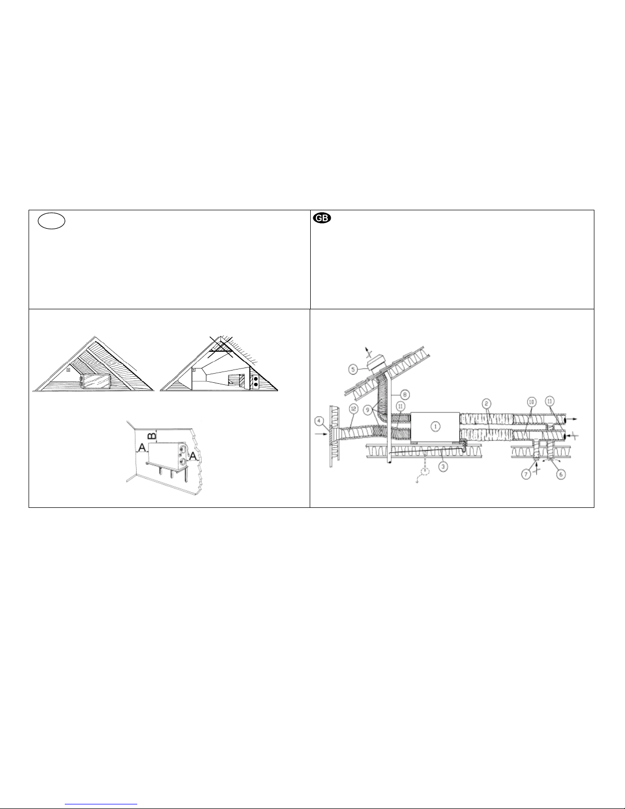
1. Inspekcijas lūka 7. Nosūces diffuzori
2. Klusinātāji pieplūde/nosūce 9. Elastīgie gaisa vadi
10. Cinkotie vītie Gaisa vadi 4. Svaigā gaisa ieņemšana
11. Siltuma izolācija 5. Gaisa izmešana
12. Sienas reste 6. Pieplūdes diffuzori
A: minimums 450 mm. B: minimums 200 mm.
1. Inspection hatch 7. Extract /extract louvers
2. Sound attenuators inlet/extract 9. Flexible ducting
10. Spiro ducting 4. Fresh air intake
11. Condensation-/ heat insulation, see separate chapter
5. Discharge extract air 12. Grade towards wall grill
6. Air inlet/inlet diffusers
A: min. 450 mm. B: min 200 mm.
Att. 1
LV
Page 4
4
Iekārtas montāža / novietošana un piekļuve (Att. 1)
Iekārtu vēlams montēt atsevišķā telpā (pieliekamajā, veļas mazgātuvē
vai līdzīgās telpās), iespējams montēt arī bēniņos.
Izvēloties iekārtas montāžas vietu, jāņem vērā skaņas līmenis un
fakts, ka iekārtai būs nepieciešama regulāra apkalpošana. Atstāt brīvu
vietu inspekcijas durvju atvēršanai un galveno komponentu
izņemšanai no iekārtas.
Tiek rekomendēts gaisa ie
ņemšanas restes montēt ēkas ziemeļu vai
austrumu pusē un attālināti no nosūces gaisa izmešanas, virtuves
nosūcējiem, centrālā putekļsūcēja, ūdens drenāžas un citiem
piesārņojuma avotiem, piemēram, satiksmes izplūdes gāzēm.
Sasmakušā gaisa izvadīšanai jānot
iek caur jumta iekārtu un attālināti
no svaigā gaisa ieņemšanas restes, logiem utt.
PIEZĪME! Jāparedz brīva telpa kondensāta novadīšanai (skatīt Att. 9)
INSTALLING THE UNIT/POSITIONING AND ACCESS (Fig. 1)
The unit should preferably be installed in a separate room (e.g.
storeroom, laundry room or similar), but can also be installed in the
loft space
When choosing the installation position, consideration must be taken
that the unit requires regular maintenance. Flooring boards must be
mounted up to and under the unit. Light should be installed Leave free
space for removing of inspection doors and main components inside
the unit.
Recommended installation location for the fresh air intake is the
northern or eastern side of the building and with a distance to
openings for discharge of stale ventilation air, kitchen ventilator,
central vacuum system, waist water drainage and other pollution
sources like exhaust from traffic etc. Stale discharge air should ideally
be led via a roof unit to outside and with a good distance to any fresh
air intake, windows etc.
NOTE! The unit must
have height for water lock (see Fig. 9).
Page 5
5
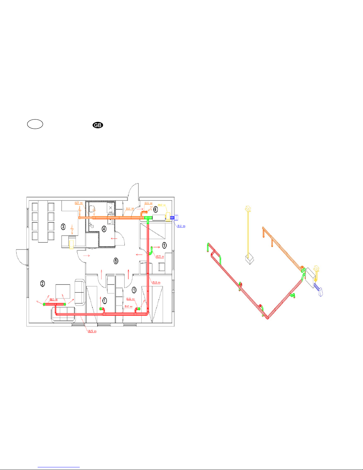
1. Guļamistaba 1. Bedroom
2. Dzīvojamā istaba 2. Living room
3. Virtuve 3. Kitchen
4. Tualete 4. Bathroom/ Laundry room
5. Halle 5. Hall
6. Pieliekamais 6. Storeroom Att.2
Att
LV
Page 6

6
Gaisa vadu sistēma
Vispārīgi (Att. 2)
Gaiss no iekārtas tiek pārvietotas pa gaisa vadiem. Lai gaisa vadiem nodrošinātu
ilgu kalpošanas laiku un iespēju tīrīt tos, tiek rekomendēts tos montēt no cinkotā
tērauda.
Īsie lokanā gaisa vada gabali (max. 1m) var tikt izmantoti, lai savienotu iekārtu ar
jumta izmešanas iekārtu vai sienas resti.
Gaisa vados jāprojektē zemi gaisa ātrumi un zemi spiediena zudumi, lai iekārta
spētu nodrošināt augstu efektivitāti, patērētu maz enerģijas un nodrošinātu vēlamo
gaisa daudzumu.
PIEZĪME!
° Nepievienot centrbēdzes žāvētāju pie ventilācijas sistēmas. Izmantot
atsevišķu sistēmu.
° Gaisa vadu pievienojumu/līkumu galiem jābūt aizvērtiem transportēšanas
un uzglabāšanas laikā
° Ieņemšanas un izmešanas restes jāmontē saskaņā ar ēkas stiprības
noteikumiem
DUCT SYSTEM
General (Fig. 2)
Air to and from the unit is led through a duct system. To ensure a long life and
satisfactory cleaning possibilities, ducts made of galvanised steel (Spiro) are highly
recommended.
Short pieces (max. 1 m) of flexible aluminium ducting can be used for connection of
the unit to roof unit/wall grill.
To obtain high efficiency, low energy consumption and required airflow, the duct
system should be commissioned for low air speeds and a low pressure drop.
NOTE!
• Do not connect tumble dryer to the ventilation system. Use separate duct
from the dryer to the open.
• Duct connections/duct ends should be covered during storage and
installation. Grill for discharge/roof unit must also be installed according to
building regulations in force
Att. 3
Att. 4
Att. 5
Page 7

7
Pievienojums gaisa vadu sistēmai (Att. 3)
Nodrošināt visus savienojumus starp gaisa vadiem un T-gabaliem,
pievienojumiem, sašaurinājumiem u.c. izmantojot speciālu lentu vai 3
skrūves uz savienojumu. "Teleskopiskiem savienojumiem" uz Systemair
Zoom jābūt ar lentu.
Trokšņu slāpēšana (Att. 4)
Lai novērstu trokšņu pārnešanos uz telpām, jāmontē trokšņu slāpētāji (1)
pie pieplūdes/nosūces gaisa vadu pievienojumiem. L=1,0m.
Lai novērstu trokšņu pārnešanos starp telpām caur gaisa vadiem, kā arī
samazinātu troksni gaisa vadu sistēmā, trokšņu slāpētājus jāmontē pirms
katra pieplūdes difuzora (Att. 6).
Lokanie gaisa vadi (Att. 4)
Lokanos gaisa vadus (2) var izmantot tikai, lai savienotu iekārtu ar jumta
izmešanu un svaigā gaisa ieņemšanas resti.
Kondensāta/siltuma izolācija
(Att. 5)
Ārgaisa un gaisa sadales gaisa vadi vienmēr ir jāizolē pret kondensāta
veidošanos. Pareiza izolācijas montāža pie gaisa vada ir ļoti svarīga. Visi
gaisa vadi, kas iet caur aukstām, neapkurinātām telpām, jābūt kārtīgi
noizolētām. Jāizmanto izolācijas pārklājums (min. 50 mm minerālvate) ar
plastisko izkliedēšanās barjeru.
Reģionos ar ļoti zemām temperatūrām ziemas periodā, jāmontē papildus
izolācija. Kopējai izolācijas biezumam jābūt vismaz 100mm.
PIEZĪME! Pārliecināties, ka visi savienojumi ir pārklāti ar izolāciju un lentu
kārtīgi.
Duct connections (Fig. 3)
Secure all joints between ducting and Tee-pieces, duct connectors, reducers
etc. by means of special tape or 3 pcs. self drilling screws per joint. Always
tape the telescopic connections on Systemair Zoom ducts.
Attenuation (Fig. 4)
To avoid fan noise being transferred to rooms, install sound attenuators (1)
on connectors for inlet air and extract air on the unit. (L = 1,0 m).
To avoid noise being transferred between rooms via the duct system and
also to reduce noise from the duct system itself, installation of sound
attenuators before every inlet diffuser is recommended. (Fig. 6).
Flexible ducting (Fig. 4)
Flexible ducting (2) to be used only for connections between the unit and
roof unit / grill for fresh air intake.
Condensation/heat insulation (Fig. 5)
Fresh air duct and discharge ducts must always be well insulated against
condensation. Correct insulation installation on ducts connected to the unit is
especially important. All duct runs installed in cold rooms/areas must be well
insulated. Use insulation sleeving (50 mm mineral wool) with plastic diffusion
barrier.
In areas with extremely low outdoor temperatures during the winter,
additional insulation must be installed. Total insulation thickness must be
at least 100 mm.
NOTE! Make sure that all joints are covered with insulation, and tape well.
Page 8

8
Pieplūdes difuzors (montējams griestos)
Inlet diffusor (ceiling mounted)
Nosūces difuzors
Extract louvre
Lokanais klusinātājs ar rāmi
Flexible silencer with frame
Att. 6
Ø125 mm Ø100 mm
Ø100/125/160 mm Ø100/Ø125 mm
LV
Page 9

9
Diffuzori/Restītes
Pieplūdes, nosūces difuzori un virtuves nosūce (Fig. 6)
Pieplūdes difuzorus montēt visās dzīvojamās istabās, ēdamistabās un
guļamistabās. Nosūces difuzorus jāmontē dušas telpās, tualetēs, virtuvēs un veļas
mazgātuvēs. Nosūces difuzoru var tikt montēti griestos. Pieplūdes difuzorus būtu
vēlams montēt griestos. Pārliecināties, ka pieplūdes difuzora gaisam priekšā nav
šķēršļu.
Gaisa plūsma no pieplūdes difuzoriem, kas montēti sienā (kur griesti ir horizontāli),
gaisa plūsmas garumam jābūt visu griestu garumā. Gaisa padeve caur nosūces
difuzoriem radīs gaisa plūsmu, un tādējādi nosūces difuzori var tikt izmantoti kā
pieplūdes difuzorus, ja tie tiek montēti sienā tuvu griestiem. Izmantot rāmjus
vieglākai difuzoru izņemšanai, lai iztīrītu gaisa vadus.
Pieplūdes difuzoru pamatiestādījumiem atvērt difuzoru pagriežot to 5 – 7 reizes no
aizvērta stāvokļa. Slēgt izmantojot centra asi. Pamatiestādījumi nosūces difuzoram
ir 10 apgriezieni no difuzora aizvērtā stāvokļa. Slēgt izmantojot centra asi.
Gaisa plūsmas iestādīšana
Gaisa ražības iestādīšana atsevišķām telpām jāveic saskaņā ar projektēšanas laikā
veiktajiem sistēmas aprēķiniem vai sistēmas palaišanas laikā (nepieciešams
speciāls mērīšanas aprīkojums).
DIFFUSERS/LOUVERS
Inlet diffusers, extract louvers and cookerhood (Fig. 6)
Mount inlet diffusers in all living rooms, dining areas and bedrooms. Extract louvers
to be installed in bathrooms, laundry room, WC and kitchen. Extract louvers can be
ceiling or wall mounted. Inlet diffuser should be mounted in the ceiling. Make sure
that the air stream from inlet diffusers has a free passage.
Air stream from inlet diffuser mounted on the wall (where the ceiling is horisontal),
must have throw length, so that the air is supplied to the room alongside the ceiling.
Air supply through extract louvers will ensure an air stream with throw length, and
extract louvers can therefore be used as inlet diffusers when mounted in the wall
close to the ceiling. Use frames to ease the removing of diffusers for cleaning.
For basic setting of inlet diffusers, open core of the diffuser 5-7 turns from closed
position. Lock by means of centre nut. For basic setting of extract louvers, open core
of the diffuser 10 turns from closed position. Lock by means of centre nut.
Setting of air volume
For adjustment of air volumes to each separate room, setting on diffusers/louvers are
to be made in accordance with calculations made during designing of the ventilation
system or during commissioning of the system (special measuring equipment
required).
Att. 7
Att. 8
Att. 9
Page 10

10
Gaisa cirkulācija starp istabām (Att. 7)
Lai iegūtu apmierinošu gaisa cirkulāciju, telpās, kurās ir pieplūdes difuzori
(dzīvojamās istabās un guļamistabās) un telpās, kurās ir nosūces difuzori (dušas
telpas, WC, virtuve, veļas mazgātuve u.c.), jābūt mazai šķirbiņai ap durvīm.
Jāmontē durvis ar spraugu rāmī, durvis bez durvju blīvējuma vai jāatstāj atvērumus
ventilācijai sienās vai durvīs (min. atvērums 70 cm
2
uz difuzoru).
Kamīns, virtuves ventilators, centrbēdzes žāvētājs u.c (Att.8)
Ja tiek izmantota VX-400/700 E iekārta, tiek sasniegta sabalansētā ventilācija. Ēkā
parasti būs pārspiediens un tādējādi nebūs risks, ka kamīna dūmu nokļūst telpā.
Lai uguns degtu efektīvi un bez traucējumiem, atklātam ugunim nepieciešams
svaigā gaisa padeve 150 - 300 m
3
/h (42 - 84 l/s). Tādējādi nepieciešams 300 cm
2
liels ventilācijas atvērums. Optimālais risinājums būtu pieplūdes gaisa vada
pievadīšana tieši uz kamīna vietu, bet arī divu 16x16 cm atvērumu ārsienā būtu labs
risinājums.
16x16 cm ventilācijas atvērumi jāparedz centrbēdzes žāvētājam un virtuves
ventilatoram (katram savs). Atvērts logs arī nodrošina nepieciešamo gaisa pieplūde
kamīna ugunim, virtuves ventilatoram un centrbēdzes žāvētājam.
Santehnikas darbi
Kondensāta novadcaurule (Att. 9)
Kondensāta novadcaurules montāža būtu jāveic kvalificētam santehniķim.
Systemair VX-400/700 E ir aprīkota ar ½ " R cauruli.
Piezīme! Ja novedcaurule ved cauri aukstām telpām, caurulei jābūt izolētai.
Air circulation between rooms (Fig 7)
To obtain a satisfactory air circulation, a small gap should exist around the doors
between rooms with inlet diffusers (living rooms and bedrooms) and rooms with
extract points (bathroom, WC, kitchen, laundry rooms etc.). Install doors with slot in
the frame, doors without doorsill or slots/vents in doors/wall (min. 70 cm
2
free area
per extract diffuser).
Fireplace, kitchen ventilator, tumble dryer etc. (Fig. 8)
Balanced ventilation is obtained where the VX-400/700 E is installed. There will
normally be no under pressure in the building, and therefore no risk for back draught
from fireplace or chimney.
An open fireplace requires an air supply of 150 - 300 m
3
/h (40 - 80 l/s) for maximum
functionality and efficiency. This equals 300 cm2 ventilation slots per fireplace. Supply
air duct directly to the fireplace would be the optimal solution, but 2 pcs. 16x16 cm
closing vents in outer wall is a good alternative.
16x16 cm vents could be installed for air supply to tumble dryer and kitchen ventilator
(one for each). These should preferable be installed in the same room. An open
window will also give the required air supply to fireplace, kitchen ventilator and tumble
dryer.
PLUMBING
Condensation drain (Fig. 9)
Installation of condensation drain should be made by authorised plumber.
Villavent VX-400/700 E is supplied with a ½ " R (outer measurement) pipe. Fixed
drain pipe to be led via water lock to frost proof drain
NOTE! If the drain pipe is led through cold rooms, the pipe must be insulated.
Page 11

11
Att. 10
Att. 10A
1. VX-400/700 E
2. Taimers, ja ir paredzēts
3. Vadības panelis
1. VX-400/700 E
2. Timer if fitted
3. Control panel
LV
Page 12

12
Elektropievienojumi (Att. 10 un 10A)
Iekārta (1)
Iekārta VX-400/700 E tiek piegādāta ar apm. 1,0m garu kabeli un kontaktdakšu,
230V, vienfāžu sazemējuma pievienojumu. 10A priekš VX-400 E un 16A priekš VX700 E.
Atsevišķs kontrolieris (3)
Systemair VX-400/700 E gaisa apstrādes iekārtas iespējams kontrolēt ar vienu vai
vairākiem CE tipa tālvadības paneļiem.
Taimers (2)
Ja gaisa apstrādes iekārta uzstādīta komerciālā ēkā, ir iespējams pieslēgt
atsevišķu nedēļas taimeri.
Papildus aprīkojums
Sīkākai informācija par difuzoriem, gaisa izmešanas ierīcēm, sienas
restītēm u.c. skatīties tehnisko katalogu un montāžas instrukcijas.
ELECTRICAL CONNECTIONS (Fig. 10 and 10A)
The unit (1)
The VX-400/700 E units are supplied with apx. 1 m cable and plug for, 230V, single
phase earthed connection. 10A for VX-400 E and 16A for VX-700 E.
Seperate controller (3)
The Villavent VX-400/700 E can be controlled from one or more remote control
panels, type CE. For necessary signal, install an unscreened, 4-lead connection
(12V). (Screened cable to be used in areas exposed to EMC noise). Use 4x0,22
or 0,5 mm2 when connected to terminal block, 4x0,14 mm2 if modular plug is
used.
The controller is adaptable in ELKO frame system, and designed for both flush
installation and for installation on the wall by means of a 18 mm double frame..
Timer (2)
If the unit is installed in commercial buildings, separate week timer for automatic
day and night operation (reduced ventilation) may be installed. Cable (2x0,22
mm2 leads) from the timer (fig 10A) to be connected to terminal block in junction
box inside the unit.
When more than one controller is installed, use one or more double inlet plugs
in the plug on the unit. as necessary.
ADDITIONAL EQUIPMENT
For more information about diffusers/louvers, roof unit, wall grill etc., see
technical catalogue and installation instructions.
Page 13

13
Gaisa plūsmas signāls
Signal airflow
Gaisa plūsmas slēdzis
Switches airflow
Pieplūdes gaisa temperatūras signāls
Signal for supply air temperature
Pieplūdes gaisa temperatūras slēdzis
Switches supply air temperature
Filtra maiņas signāls Signal filter change
Vasaras režīma signāls Signal summer operation
Filtra nomaiņas laika pārstādīšana Switch override week timer
Sildītāja darbības signāls Lamp indicator heater battery
Att. 11
PALAIŠANA EKSPLUATĀCIJĀ
Kad montāža ir pabeigta, pārbaudīt, ka:
Uzmanību! Ja iekārtas ieslēgšanās tiek aizkavēta, ir jāpārbauda
gaisa vadu sistēma (ar aizbāzni), lai nodrošinātu gaisa
cirkulāciju. Tas novērš kondensāciju un bojājumus iekārtā.
1. Iekārta ir uzmontēta saskaņā ar instrukcijām.
2. Ir uzmontēti trokšņu slāpētāji vai, ka gaisa vadi ir pareizi pievienoti
iekārtai.
3. Ka nav troksnis no difuzoriem un restītēm.
4. Svaigā gaisa ieņemšana un izmešana ir uzmontēta tā, lai novērstu
nosūces gaisa recirkulāciju.
5. Svaigā gaisa ieņemšana ir izvietota pietiekamā attālumā no
piesārņojuma avota (virtuves nosūces ventilatora, centrālā
putekļsūcēja izmešanas u.c.).
6. Vadības panelis un gaismas signāli darbojas (skatīt lietošanas un
apkalpošanas instrukciju, “Darbība”).
7. Nedēļas taimeris (ja uzstādīts) pievienots sistēmai darbojas (skatīt
lietošanas un apkalpošanas instrukciju, „Darbība no taimera”).
COMMISSIONING
When the installation is finished, check that:
NB! If start-up of the system is delayed, the duct system must be
protected (by means of bungs) so that air circulation is prevented.
This is to avoid condensation and damage in the ventilation unit.
1. the unit is installed in accordance with instructions.
2. sound attenuators are installed and that the duct system is correctly
connected to the unit.
3. there is no noise from the unit or from diffusers and louvers.
4. fresh air intake and discharge is installed so that short circuit of the air
streams is avoided.
5. fresh air intake is positioned with sufficient distance to pollution source
(kitchen ventilator exhaust, central vacuum system exhaust or similar).
6. control functions are operating (see user and maintenance instructions,
"Operation").
7.
Timer (if installed) connected to the system is operating (see User and
maintenance instructions, „Operation from timer”).
LV
Page 14

14
Pirms sistēmas palaišanas:
1. Izvēlēties gaisa plūsmu pie Vidēja ventilatora ātrumu (augsts/zems) vadības
panelī. (Att. 11).
VX-400 E
Vidēji zems ventilatora ātrums tiek lietots, kad gaisa paredzētais gaisa
daudzums ir zemāks par 50 l/s (180 m3/h) / ventilējamā platība mazāka par 150
m
2
. Vidēji augsts ventilatora ātrums tiek lietots kad paredzētais gaisa daudzums
ir lielāks par 50 l/s (180 m3/h)/ ventilējamā platība lielāka par 150 m2.
VX-700 E
Vidēji zems ventilatora ātrums tiek lietots, kad gaisa paredzētais gaisa
daudzums ir zemāks par 70 l/s (250 m3/h) / ventilējamā platība mazāka par 210
m2. Vidēji augsts ventilatora ātrums tiek lietots kad paredzētais gaisa daudzums
ir lielāks par 70 l/s (250 m3/h)/ ventilējamā platība lielāka par 210 m2.
Vidēji augstu ventilatora ātrumu var iegūt vienlaicīgi nospiežot pogas (13) un (4).
Iestādījumi tiek apstiprināti mirgojot indikatoriem (2) un (3). Vidēji zems
ventilatora ātrums tiek ieslēgts vienlaicīgi nospiežot pogas (13) un (5).
Iestādījumi tiek apstiprināti mirgojot indikatoriem (1) un (2).
2. Restītes un difuzorus ieregulēt saskaņā ar palaišanu vai pamata iestādījumiem
(skatīt "Difuzori/Restītes"). Pārliecināties, ka pieplūdes difuzora gaisa plūsma
nevirzās uz izvirzītu siju, sienu u.c.
3. Izvēlēties pieplūdes gaisa temperatūru (skatīt lietotāja un apkalpošanas
instrukciju, “Darbība”).
4. Izvēlēties filtra darbības laiku (att. 11). Rūpnīcas standartiestādījums ir 9
mēneši. Tas ir pietiekošs laiks apkārtnei, kur ārgaisam ir pieņemama kvalitāte.
Jā ārgaisu piesārņo satiksmes izplūdes gāzes, rūpniecība, filtri jāmaina reizi 6
mēnešos. Pat ja ārgaisa kvalitāte ir laba un ārgaiss nav piesārņots, filtra
kalpošanas laiks ir 12 mēneši (Smakas un organiskie piesārņojumi pasliktinās
gaisa kvalitāti). Lai palielinātu vai samazinātu filtra kalpošanas laiku, vienlaicīgi
jānospiež pogas (13) un (9) vai (13) un (10). Iestādījumi tiek apstiprināti mirgojot
indikatoram 14 un pastāvīgi deg indikators:
- indikators (6) 6 mēnešu darbības laiks starp filtru nomaiņu
- indikators (7) 9 mēnešu darbības laiks starp filtru nomaiņu
- indikators (8) 12 mēnešu darbības laiks starp filtru nomaiņu
Before starting the system:
1. Chose airflow at normal fan speed (high/low) on the control panel (fig. 11).
VX-400 E
Normal fan speed Low is used when dimensioned airflow is lower than 50 l/s
(180 m3/h) / ventilated area is less than 150 m2. Normal fan speed High is used
when dimensioned airflow is over 50 l/s (180 m3/h)/ ventilated area is over 150
m
2
.
VX-700 E
Normal fan speed Low is used when dimensioned airflow is lower than 70 l/s
(250 m3/h) / ventilated area is less than 210 m2. Normal fan speed High is used
when dimensioned airflow is over 70 l/s (250 m3/h)/ ventilated area is over 210
m2.
Chose normal airflow High by pressing buttons (13) and (4) simultaneously.
Setting is confirmed by flashing light in lamp (2) and (3). Normal airflow Low is
chosen by pressing buttons (13) and (5) simultaneously. Setting is confirmed by
flashing light in lamp (1) and (2).
2. Adjust diffusers and louvers in accordance with commissioning or basic setting
(see "Diffusers/Louvers"). Make sure that the inlet diffusers are set so that the air
stream is not lead towards visible joist, wall etc. close to the diffuser.
3. Chose supply air temperature (see user and maintenance instructions,
"Operation").
4. Chose operation time for filter (fig. 11). Standard factory setting is 9 months. This
is sufficient in areas where the outdoor air has a satisfactory quality. If the
outdoor air is polluted by exhaust from traffic, industry etc, filter change every 6
months is recommended. Even if the outdoor air quality is good, and the fresh air
filter is not clogged, max. recommended operation time for filters is 12 months
(Smells and organic pollution will reduce the supply air quality). To increase or
reduce the operation time for filters, press buttons (13) and (9) or (13) and (10)
simultaneously. Setting is confirmed by flashing light in lamp (14) and constant
light in:
- lamp (6) for 6 months operation time between filter change
- lamp (7) for 9 months operation time between filter change
- lamp (8) for 12 months operation time between filter change
Page 15

15
Instrukcijas var tikt mainītas bez
iepriekšējas brīdināšanas.
Specifications may be changed without
notice.
Ražotājs/Hersteller/Manufacturer:
www .systemair. com
LV
 Loading...