

Page 1

SAVE VTR 300/B
Installation instructions
Document in original language | 229391 · v02
GB
Page 2

© Copyright Systemair UAB
All rights reserved
E&OE
Systemair UAB reserves the rights to alter their products without notice.
This also applies to products already ordered, as long as it does not affect the previously agreed specifications.
Systemair is not liable or bound by warranty if these instructions are not adhered to during installation or service.
229391 | v02
Page 3

1 Overview . .. ....... .... .... .... ......... .... .... .... .... .... ...1
1.1 Warranty.. ............. .... .... .... .... ............. ..1
1.2 Type label.. .... .... .... .... .... ..... ........ .... .... ..1
1.3 Disposal and recycling .... .... .... .... .... .... .....1
2 Important Safety Information ..... .... .... .... .... .... ....1
2.1 Intended Use... ..... .... .... .... .... .... .... ..... ....2
2.2 Admonitions .... .... ............. .... .... .... .... ....2
3 Technical Data .... .... .... .... ......... .... .... .... .... .......2
3.1 Power consumption and fuse size .... .... .... ..2
3.2 Dimensions and Weight .... .... .... .... ...........3
3.3 Connections Left and Right models.. .... .... ...5
3.4 Installation recommendation regarding
condensation .... ........ .... .... .... .... ......... ...5
3.4.1 Condensation inside of the
unit . .... .... .... ......... .... .... .... .... ...5
3.4.2 Condensation outside of the
unit . .... .... .... ......... .... .... .... .... ...6
4 Delivery, Transport, Storage..... .... .... .... .... .... .... ..6
4.1 Transport and storage . .... .... ..... .... .... .... ...6
4.2 Delivery/Unloading. ............. .... .... .... .... ...6
5 Prerequisites for Installation.... .... .... .... .... ......... ..6
5.1 Location and Space Requirements..... .... .... .7
5.2 Wall preparation for mounting
bracket .... ............. .... .... .... .... ............. ..7
5.3 Condensation drainage . .... ..... .... .... .... .... ..7
5.4 Outdoor Air Intake Location
Recommendation.. .... .... ............. .... .... .... 7
5.5 Access to Power supply .... ..... ........ .... .... ..7
6 Installation.. .... .... .... ........ ..... .... .... .... .... .... ......7
6.1 Ventilation Duct Connection and
Insulation .... .... .... .... .... .... ......... .... .... .... 9
6.2 Installation and Configuration of
Accessories............ .... .... .... .... ............. ..9
7 Before Starting the System........ .... .... .... .... ........9
8 Commissioning .... .... .... .... .... ..... .... .... .... .... .... 10
9 Concluding Routines .. .... ..... .... .... .... .... .... .... ... 10
10 EU Declaration of Conformity . .... .... .... ............. . 11
Contents
229391 | v02
Page 4

Page 5

Overview
|
1 Overview
Read the instructions carefully and in its entirety.
For description of advanced settings and installation of accessories see Service and Accessories Installation manual.
All documents can be found in our online catalogue at www.systemair.com.
1.1 Warranty
For the assertion of warranty claims, the products must be correctly connected and operated, and used in accordance
with the data sheets. Further prerequisites are a completed maintenance plan with no gaps and a commissioning report. Systemair will require these in the case of a warranty claim.
1.2 Type label
Before calling your service representative, make a note of the specification and production number from the type label,
which can be found next to the external connections and inside of the unit.
1
Position Description
1
2
3
4
5
6
7
Product code (product specification)
Product item number
Production order number
Serial number
Production date (YY.MM.DD)
QR code for manufacturing order (MO) number and software version
QR code for the spare parts list and documentation
1.3 Disposal and recycling
This product is compliant with the European WEEE Directive and related national waste
legislation. When disposing the unit, follow your local rules and regulations.
This product packing materials are recyclable and can be reused. Do not dispose in household
waste.
Fig. 1 Type label
2 Important Safety Information
• Observe and respect local conditions, regulations and laws.
229391 | v02
Page 6

| Technical Data
2
• Safety elements may not be dismantled, circumvented or deactivated.
• Wear protective equipment during all work in the vicinity of the unit.
• Do not allow children to play with the device.
2.1 Intended Use
• Abide by the system-related conditions and requirements of the system manufacturer or plant constructor.
• Keep all the warning signs on the device and in a legible condition.
• The device is not to be used by persons (including children) with reduced physical, sensory or mental capabilities, or
lack of experience and knowledge, unless they have been given supervision or instruction.
• The system should operate continuously, and only be stopped for maintenance/service.
• Do not connect tumble dryers to the ventilation system.
• Make sure that filters are mounted before starting the unit.
2.2 Admonitions
Danger
• Make sure that the mains supply to the unit is disconnected before performing any maintenance or
electrical work!
• All electrical connections and maintenance work must be carried out by an authorized installer and in
accordance with local rules and regulations.
Warning
• This product is not intended to be used by children or people with reduced physical or mental ability or
lack of experience and knowledge, if no instruction concerning the use has been given by the person
responsible for their safety or that this person is supervising the operation. Children should be supervised
so that they can not play with the product.
• Beware of sharp edges during mounting and maintenance. Use protective gloves.
Warning
• Risk of injury due to rotating parts that have not come to a complete standstill after mains supply to the
unit have been disconnected.
3 Technical Data
3.1 Power consumption and fuse size
Re-heater
Fans 176 W
Total power consumption
Fuse 10 A
1670 W
1846 W
229391 | v02
Page 7
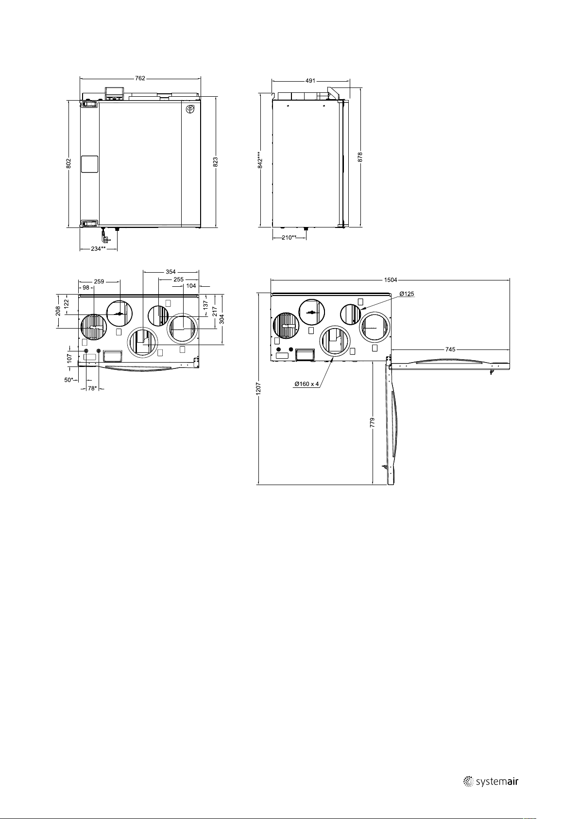
3.2 Dimensions and Weight
Technical Data |
3
Fig. 2 Dimensions of left hand unit
229391 | v02
Page 8
4
| Technical Data
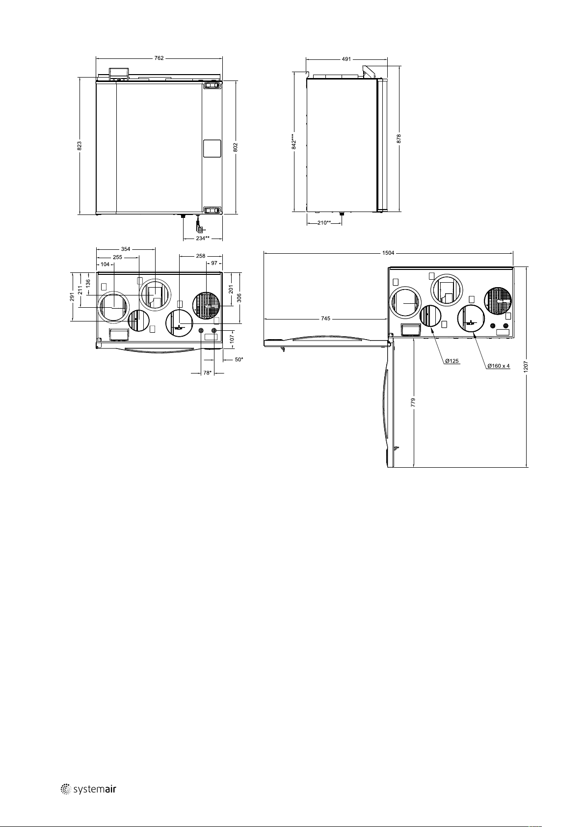
Fig. 3 Dimensions of right hand unit
* Water coil connections.
** Drainage.
*** Height with mounting bracket.
The unit weight is 56 kg.
229391 | v02
Page 9

3.3 Connections Left and Right models
Position Description
R
L
Right hand model (Supply air connection is situated on the right hand side of the unit
viewed from the front)
Left hand model (Supply air connection panel is situated on the left hand side of the unit
viewed from the front)
Technical Data |
5
Symbol
Description
Supply air
Exhaust air
Symbol
Description
Outdoor air Cooker hood air
Extract air
Symbol
Description
3.4 Installation recommendation regarding condensation
3.4.1 Condensation inside of the unit
When the unit is installed in a cold attic (close to outdoor temperature) the unit should run continuously. If the unit is intended to be stopped by the user manually or due to calendar function we recommend to install air tight dampers at extract and supply air ducts. The dampers will ensure that no air circulates from the warm parts of the building through
the unit to outside (chimney effect). If no dampers are installed there is risk of condensation inside the unit and the outdoor ducts during these stop periods. It also might be that cold air from outside could pass the unit and enter into the
building. That could cause condensation outside the supply and extract air ducts and even at the valves in the rooms.
When the unit is not running due to late commissioning in winter time, the supply and extract air ducts should be disconnected and closed due to above mentioned effects until commissioning and regular operation.
229391 | v02
Page 10
| Delivery, Transport, Storage
6
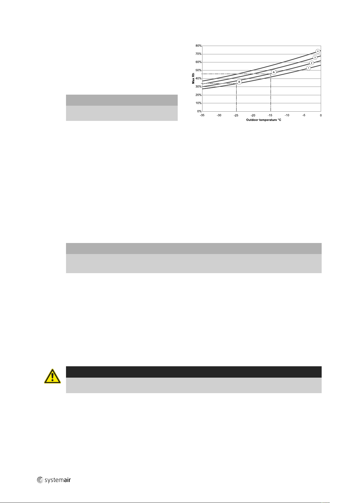
3.4.2 Condensation outside of the unit
When the unit is installed in warm humid areas (like laundry) together with low outdoor temperature there is a
certain point where moisture can condense outside of the
casing. The condensation relation to indoor relative humidity, room and outdoor temperature is shown diagram
below. The condensation outside of the unit do not occur
in zones bellow each curve.
Important
Recommendation: If condensation occurs,
increase ventilation in area close to the unit.
Examples when condensation outside of the unit can
occur:
Example A: If the unit is installed in room where temperature is 22°C, outside temperature is –15°C, then dew will
start accumulating when relative humidity is 46% and
higher.
Example B: If the unit is installed in room where temperature is 20°C, outside temperature is –25°C, then dew will start
accumulating when relative humidity is 34% and higher.
1. Room temperature 20°C
2. Room temperature 22°C
3. Room temperature 24°C
4. Room temperature 26°C
4 Delivery, Transport, Storage
4.1 Transport and storage
The SAVE VTR 300/B should be stored and transported in such a way that it is protected against physical damage. It
should be covered so dust, rain and snow cannot enter and damage the unit and its components.
Important
• Use the packaging exclusively as transport protection and not as a lifting aid.
• Load and unload the air handling unit carefully.
4.2 Delivery/Unloading
The appliance is delivered in one piece containing all necessary components, wrapped in plastic on a pallet for easy
transportation.
Checking delivery
• Check the packaging and the air handling unit for transport damage. Any findings should be noted on the cargo
manifest.
• Check completeness of the delivery.
Verify that all ordered equipment is delivered before starting the installation. Any discrepancies from the ordered
equipment must be reported to the supplier of Systemair products.
Warning
When opening the transport packaging, there is a risk of damage from sharp edges, nails, staples, splinters
etc.
Unpacking
• Check the air handling unit for visible transport damage.
• Only remove the packaging shortly before assembly.
• Beware of sharp edges during mounting and maintenance. Use protective gloves.
5 Prerequisites for Installation
To ensure a proper and fail-free operation, it is important that the unit is installed according to these instructions.
229391 | v02
Page 11
Installation |
5.1 Location and Space Requirements
The SAVE VTR 300/B should preferably be installed in a separate room (e.g. storeroom, laundry room or similar.).
When choosing the location it should be kept in mind that the unit requires maintenance regularly and that the inspection door should be easily accessible. Leave free space for opening the door and for taking out the main components
(figure 3.2).
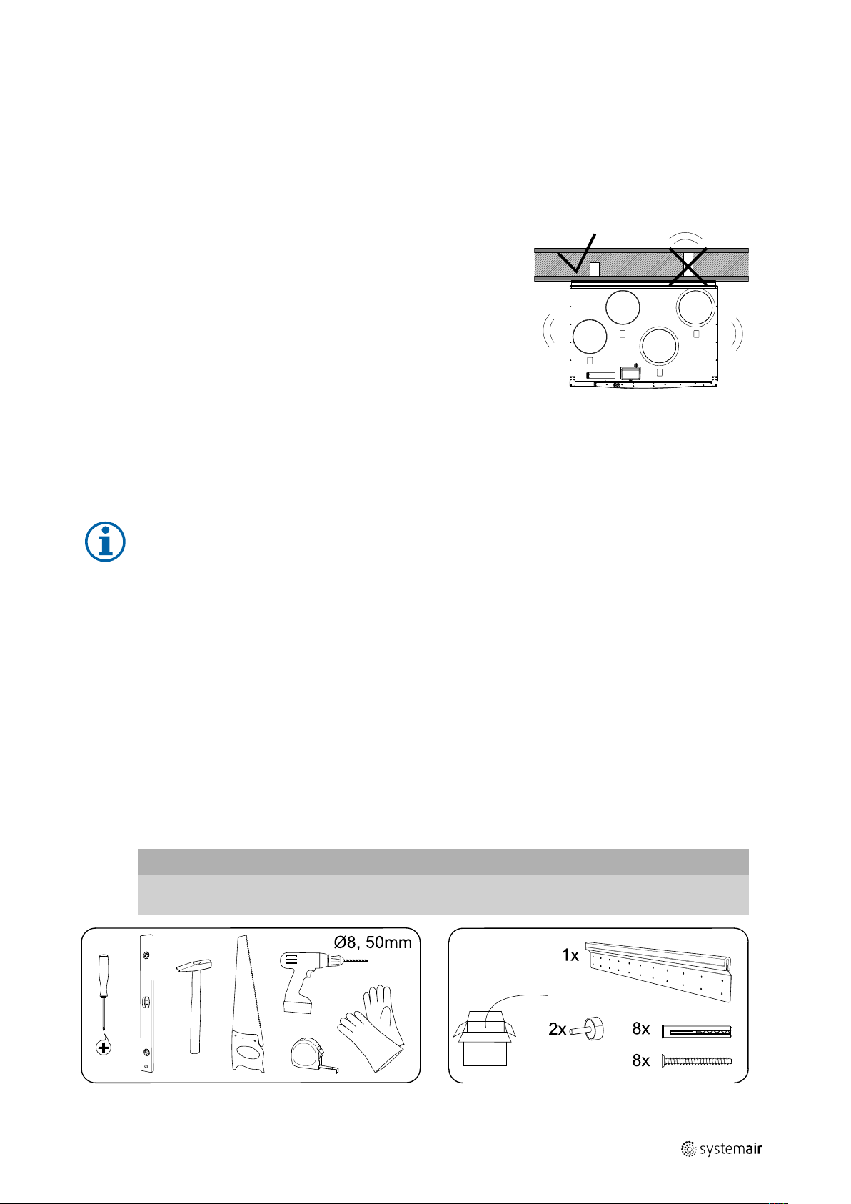
5.2 Wall preparation for mounting bracket
The unit should be installed in such a way that there is no vibration noise
coming from the wall on which the unit is installed.
5.3 Condensation drainage
In general no condensation drainage is needed for rotational heat exchangers at dry conditions. However, if a lot of humid air is present in the residence, a condensation drainage might be needed. Drainage connection is available as an accessory and can be ordered separately. Installation instructions for the drainage are enclosed in the drainage pipes
delivery.
7
Note:
The drainage connection is plugged in the bottom of the unit at delivery. To use the drainage: remove the
rubber seal and connect the drainage pipe. Connect the drainage pipe to the sewer. The water can not be
led straight to the sewer without a water trap.
5.4 Outdoor Air Intake Location Recommendation
Recommended installation location for the outdoor air intake is the northern or eastern side of the building and with a
distance to openings for discharge of stale ventilation air, kitchen ventilator, central vacuum system, waste water drainage and other pollution sources like exhaust from traffic, etc. Exhaust air should ideally be led via a roof cowl to the outside and with a good distance from the outdoor air intake, windows, etc.
5.5 Access to Power supply
The SAVE VTR 300/B is supplied with approximately 1,5 m cable and plug for 230V, single phase earthed connection.
Make sure a power outlet is reachable by the plug.
6 Installation
Important
The device may only be installed by qualified, instructed and trained personnel. The persons must know the
relevant safety directives in order to recognise and to avoid risks.
229391 | v02
Page 12

8
| Installation
C — concrete/bricks, W — wood block, G — gypsum, M — mineral wool
X* — adaptable height according to needs.
Make sure the mounting bracket is completely level.
229391 | v02
Page 13

Follow the ventilation drawing when connecting the unit to the duct system.
Before Starting the System |
9
6.1 Ventilation Duct Connection and Insulation
Important
• Always cover the ventilation ducts during construction period.
• Make sure there are no loose objects or impurities inside the ducts.
Install the ducts, supply air diffusers and air intake grilles as shown in the ventilation drawing.
• Supply air and extract air ducts must be insulated if located in cold places.
• Outdoor air and exhaust air ducts with cold air must be insulated if located in warm places (inside building’s vapour
barrier).
It is very important to insulate cold ducts and joints tightly without any gaps, otherwise there is a risk of condensation
which may result in moisture damage.
Do not install the ducts directly against structural building elements to avoid sound propagation. Use acoustic insulation
and sound attenuators.
Note:
The type of ventilation ducts and insulation differ for each building and climate zone. If the ventilation
drawing is not provided, please contact your installer or place of purchase for recommendations.
6.2 Installation and Configuration of Accessories
Please follow instructions included with the accessory or consult “Service and Accessories Installation” manual which
can be found in our online catalogue.
7 Before Starting the System
When the installation is completed, check that:
• The unit is installed in accordance with the instructions
• Outdoor and exhaust air dampers and silencers are installed and that the duct system is correctly connected to the
unit
• All ducts are sufficiently insulated and installed according to local rules and regulations
• Outdoor air intake is positioned with sufficient distance to pollution sources (kitchen ventilator exhaust, central vacuum system exhaust or similar)
• All external equipment is connected
229391 | v02
Page 14

Commissioning
|
10
• The unit is correctly wired
8 Commissioning
Follow the first startup instructions and fill in the Commissioning record as you go through the settings.
The Startup Wizard cannot be skipped.
Select language, set the time and choose airflow control type. Select revolutions per minute as the type of airflow control only if these values are included with the device.
Set speed of supply and extract air fans for each level. When finished, review your settings. It is possible to go back to
previous menus and make modifications. Finally choose heating type or none. Finish startup wizard with OK button.
All additional changes post-startup wizard must be recorded in the Commissioning record.
9 Concluding Routines
Perform the following procedures before leaving the site:
1. Ensure that the product is operational and that no alarms are active.
2. If applicable, save the configuration backup.
3. Make sure that the Commissioning record is complete.
4. Collect all tools.
5. Inform the appropriate person that work is finished.
6. Follow the procedures for the return and disposal of replacement parts and the disposal of packing.
229391 | v02
Page 15
10 EU Declaration of Conformity
EU Declaration of Conformity |
11
Manufacturer
Systemair UAB
Linų st. 101
LT–20174 Ukmergė, LITHUANIA
Office: +370 340 60165
Fax: +370 340 60166
www.systemair.com
The manufacturer hereby confirms that
SAVE VTR 300/B
comply with all applicable requirements in the following
directives and regulations.
Machinery Directive 2006/42/EC
Ecodesign Directive 2009/125/EC
327/2011 Requirements for fans above 125 W
1253/2014 Requirements for ventilation units
1254/2014 Energy labelling of residential ventilation units
Low Voltage Directive 2014/35/EU
EMC Directive 2014/30/EU
RoHS Directive 2011/65/EU, 2015/863/EU
The following harmonized standards are applied in applicable parts:
EN ISO 12100
Safety of machinery - General principles for design - Risk
assessment and risk reduction.
EN 13857
Safety of machinery – Safety distances to prevent hazard
zones being reached by upper or lower limbs.
EN 60529
Degrees of protection provided by enclosures (IP Code).
EN 62233
Measurement methods for electromagnetic fields of
household appliances and similar apparatus with regard
to human exposure.
EN 61000-6-2
Electromagnetic compatibility (EMC) – Part 6-2: Generic
standards – Immunity for industrial environments.
EN 61000-6-3
Electromagnetic compatibility (EMC) – Part 6-3: Generic
standards – Emission standards for residential, commercial and light-industrial environments.
EN 13053
Ventilation for buildings – Air handling units – Rating and
performance for units, components and sections.
EN 13142
Ventilation for buildings. Components/products for residential ventilation. Required and optional performance
characteristics
The declaration applies only to product in the condition it
was delivered in and installed in the facility in accordance
with the included installation instructions. The insurance
does not cover components that are added or actions
carried out subsequently on the product.
The complete technical documentation is available.
Ukmergė, 13-01-2021
EN 60204-1
Safety of machinery – Electrical equipment of machines –
Part 1: General requirements.
EN 60335-1
Household and similar electrical appliances – Safety Part
1: General requirements.
EN 60335-2-40
Safety of household and similar electrical appliances Part 2-40: Particular requirements for electrical heat
pumps, air-conditioners and dehumidifiers.
EN 50106
Safety of household and similar appliances – Particular
rules for routine tests referring to appliances under the
scope of EN 60 335-1.
Nerijus Lapackas
Technical Manager
229391 | v02
Page 16

Systemair UAB
Linų st. 101
LT–20174 Ukmergė, LITHUANIA
Phone +370 340 60165
Fax +370 340 60166
www.systemair.com
SAVE VTR 300/B · Installation instructions · 229391 · en_GB · 2021-02-05 · v02
 Loading...