

SystemAir VSC Series, VSC 700, VSC 700 HW, VSC 1500, VSC 1500 EL Installation Instructions Manual
...Page 1
VSC
Compact Air Handling Unit
Installation instructions GB
V1 (1/2)
Page 2
© Copyright Systemair AB
All rights reserved
E&OE
Systemair AB reserves the rights to alter their products without notice.
This also applies to products already ordered, as long as it does not aect the previously agreed specications.
Operation and Maintenance Instructions
2
Systemair AB
Page 3
Contents
1 Warnings........................................................................................................................................................... 4
2 Product information........................................................................................................................................... 4
2.1 General ..................................................................................................................................... 2
2.2 Technical data ........................................................................................................................... 5
2.2.1 Dimensions and weight ...........................................................................................................5
2.2.2 Space required ........................................................................................................................8
2.2.3 Electrical data VSC .................................................................................................................9
2.3 Transport and storage ...................................................................................................................... 9
3 Installation ........................................................................................................................................................10
3.1 Unpacking .......................................................................................................................................10
3.2 Where/how to install.........................................................................................................................10
3.3 Condensation drain..........................................................................................................................11
3.4 Condensation drain..........................................................................................................................12
3.4.1 Installation procedure ...........................................................................................................13
3.5 Connections.....................................................................................................................................14
3.5.1 Ducting .................................................................................................................................14
3.5.2 Condensation and heat insulation.........................................................................................15
3.5.3 Silencers................................................................................................................................15
3.5.4 Electrical connections, components .....................................................................................15
3.5.5 External connections ............................................................................................................17
3.5.6 BMS Connection...................................................................................................................18
Operation and Maintenance Instructions
3
Systemair AB
Page 4
1 Warnings
The following admonitions will be presented in the dierent sections of the document:
Danger
• Indicates a potentially or imminently hazardous situation which, if not avoided, could result in
death or serious injury.
Warning
• Indicates a potentially hazardous situation that may result in minor or moderate injuries.
Caution
• Indicates a risk of damaging the product or prevent optimal operation.
Important
• This appliance can be used by children aged from 8 years and above and persons with reduced physical, sensory or mental capabilities or lack of experience and knowledge if they have
been given supervision
• or instruction concerning use of the appliance in a safe way and understand the hazards
involved.
• Children shall not play with the appliance. Cleaning and user maintenance shall not be made
by children without supervision.
2 Product information
2.1 General
This installation manual concerns air handling unit type Topvex FC manufactured by Systemair Sverige AB. The units
include the following model options:
• Model: VSC 700, VSC 1500, VSC 2000
• Heating coil: EL (Electric), HW (Water coil) or None.
This manual consists of basic information and recommendations concerning the design, installation, start-up and operation, to ensure a proper fail-free operation of the unit.
The key to proper and safe operating of the unit is to read this manual thoroughly, use the unit according to given
guidelines and follow all safety requirements.
Operation and Maintenance Instructions
4
Systemair AB
Page 5
2.2 Technical data
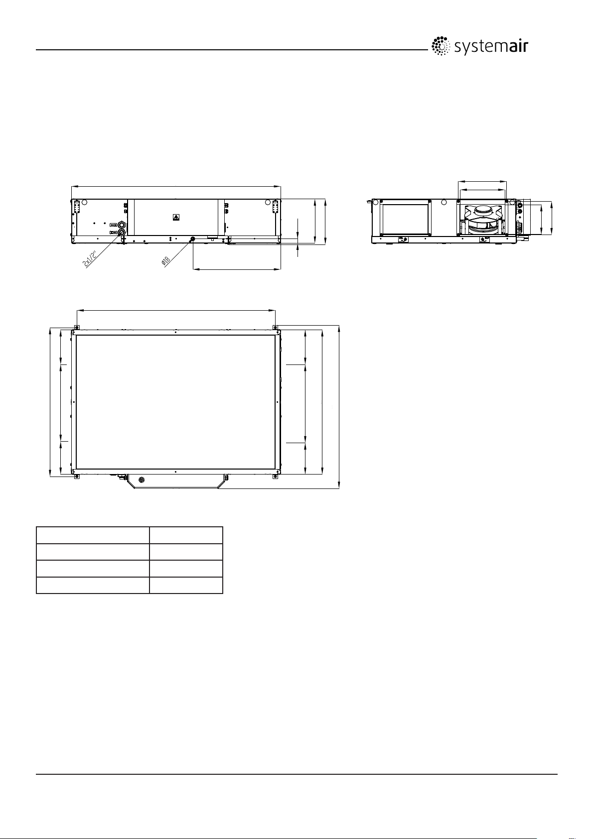
2.2.1 Dimensions and weight
1000
242
517242
1400
1330
590
324
300
224
21
300
310
970
517 242242
1096
200
Model Weight, kg
VSC 700 90
VSC 700 EL 95
VSC 700 HW 95
Operation and Maintenance Instructions
Systemair AB
5
Page 6

323
1700
1630
720
524
500
274
21
380
390
250
1305
625323
Model Weight, kg
VSC 1500 165
VSC 1500 EL 170
VSC 1500 HW 170
625 323323
1270
1400
Operation and Maintenance Instructions
6
Systemair AB
Page 7

433
2000
1630
902
624
600
324
21
460
470
300
1630
735433
Model Weight, kg
VSC 2000 240
VSC 2000 EL 245
VSC 2000 HW 245
735 433433
1600
1728
Operation and Maintenance Instructions
7
Systemair AB
Page 8

2.2.2 Space required
W
Model W (mm)
VSC 700 350
VSC 1500 450
VSC 2000 550
Operation and Maintenance Instructions
8
Systemair AB
Page 9

2.2.3 Electrical data VSC
Model Fans (W tot.) 230V 1~ El Heating battery (kW tot.) Fuse (mains) (A) for 230V 1~ and
400V 3~
VSC 700
EL
VSC 700
None, HW
VSC 1500
EL
VSC 1500
None, HW
VSC 2000
EL
VSC 2000
None, HW
330 1,4 16
330 - 10
910 2,7 25
910 - 10
1000 4,8 3x16
1000 - 10
2.3 Transport and storage
VSC is delivered in one piece on a pallet for easy transportation using a forklift. The unit should be stored
and transported in such a way that it is protected against physical damage that can harm panels, handles, display etc.
It should be covered so that dust, rain and snow cannot enter and damage the unit and its components. The appliance
is delivered complete with all necessary components, wrapped in plastic on a pallet for easy transportation.
At delivery the unit is fastened to the pallet with 4pcs screws. Unscrew the srews from the pallet.
When transporting the VSC units use a forklift.
Fig. 1
Operation and Maintenance Instructions
Systemair AB
9
Page 10

NOTE:
Necessary parts like control panel, supply air sensor, handles, drainage pipe with drain trap are placed
loosely inside the unit. The unit must not be put into operation before the enclosed parts are removed and
installed properly.
Warning
• The unit is heavy. Be careful during transport and mounting. Risk of injury through pinching. Use protective
clothing.
• Be careful so the unit don‘t tip over.
3 Installation
VCS is designed for installation above suspended ceilings.
Fig. 2
3.1 Unpacking
Verify that all ordered equipment are delivered before starting the installation. Any deviation from the ordered equipment must be reported to the supplier of Systemair products.
3.2 Where/how to install
VSC are meant for indoor installation. The electronic components should not be exposed to lower temperature
than 0° C and higher than +50° C.
VSC must always be installed horizontally with the inspection doors downwards.
When choosing the location it should be kept in mind that the unit requires maintenance regularly and that the inspec-
tion doors should be easily accessible. Leave free space for opening the doors and for taking out the main components (chapter 2.2.2.)
NOTE:
If there is not sucient space to open the inspection doors, it is possible to mount rails and use existing doors as
sliding doors (accessory) chapter 4.6.
The outdoor air intake of the building should if possible be put in the northern or eastern side of the building and away
from other exhaust outlets like kitchen fan outcasts or laundry room outlets.
Warning
• The unit must be duct connected or in some other way provided with protection so that it is not possible to come
in contact with the fans through the duct connections
10
Operation and Maintenance Instructions
Systemair AB
Page 11

3.3 Condensation drain
The unit must be connected to the condensation drain.
See table 1 how the height “H” corresponds to dierent maximum negative pressures.
If the unit is mounted in a tight area that makes it dicult to have the appropriate height, a pump is available as an
accessory.
Note:
When installed in a non heated place the drain pipe and trap needs to be insulated well to prevent the water from
freezing.
Fig. 3
H
Fig. 4 - Drainage connection
Table 1
H (mm) Max. Negative pressure (Pa)
65 300
95 600
135 1000
NOTE: It is recommended to use a ball trap siphon
Operation and Maintenance Instructions
Systemair AB
11
Page 12

3.4 Installing the unit
The units are designed for ceiling installation
Fig. 5
SUP
ETA
ODA
ETA
Table 2 Symbol description
Symbol Description
Supply air
Exhaust air
Outdoor air
Extract air
Operation and Maintenance Instructions
Systemair AB
12
Page 13

3.4.1 Installation procedure
The units are designed for ceiling installation
Warning
• Beware of sharp edges during mounting and maintenance. Make sure that a proper lifting
device is used. Use protective clothing.
Warning
• The units electrical connection to the mains power supply must be preceded by an all pole
circuit breaker with a minimum 3 mm gap.
Danger
• Make sure that the mains power supply to the unit is disconnected before performing any
maintenance or electrical work!
• All electrical connections must be carried out by an authorized installer and in accordance
with local rules and regulations.
1)
Prepare the surface where the unit is to be mounted. Make sure that the surface is at, levelled and that it
carries the weight of the unit. Perform the installation in accordance with local rules and regulations.
Install the unit with 0-3° lean towards drainage connections.
2)
Li the unit in place.
3)
Connect the unit electrically to the mains power supply through the all pole circuit breaker (safety switch).
Led the wiring directly to the electrical connection box. Be careful not to cut the wiring.
13
Operation and Maintenance Instructions
Systemair AB
Page 14

3.5 Connections
3.5.1 Ducting
8
1
SUP
4
ETA
Fig. 6 Connections and basic components
7
5
6
3
ODA
2
ETA
Position Description Symbol
A Connection supply air (SUP)
B Connection exhaust air (EHA)
C Connection outdoor air (ODA)
D Connection extract air (ETA)
1 Fan supply air
2 Fan extract air
3 Filter supply air
4 Filter extract air
5 Heat exchanger
6 Electrical connection box
7 Damper by-pass outdoor air
8 Re-heater battery with manual everheat protection
14
Operation and Maintenance Instructions
Systemair AB
Page 15

3.5.2 Condensation and heat insulation
on ducts connected to the unit is especially important. All ducts installed in cold rooms/areas must be well insulated.
Use insulating covering (minimum 100 mm mineral wool) with plastic diusion barrier. In areas with extremely low
outdoor temperatures during the winter, additional insulation must be installed. Total insulation thickness must be at
least 150 mm.
Caution
• If the unit is installed in a cold place make sure that all joints are covered with insulation, and
tape well
• Duct connections/duct ends should be covered during storage and installation
• Do not connect tumble dryers to the ventilation system
3.5.3 Silencers
To avoid fan noise being transferred via the duct system, silencers should be installed both on supply and extract air.
To avoid noise being transferred between rooms via the duct system and also to reduce noise from the duct system
itself, installation of silencers before every inlet diuser is recommended.
3.5.4 Electrical connections, components
Danger
• Make sure that the mains power supply to the unit is disconnected before performing any
maintenance or electrical work!
• All electrical connections must be carried out by an authorized installer and in accordance
with local rules and regulations.
Warning
• The units electrical connection to the mains power supply must be preceded by an all pole
circuit breaker with a minimum 3 mm gap.
All electrical connections are made in the electrical connection box which can be found on the long side of the unit.
The hatch is removed by unscrewing one screw (gure 7).
The unit must not be put into operation before all the electrical safety precautions have been read and understood.
See the enclosed wiring diagram for internal and external wiring.
All external connections to possible accessories are made to terminals inside the electrical connection box (chapter
3.5.5).
15
Operation and Maintenance Instructions
Systemair AB
Page 16

Fig. 7
VSC units are equipped with a built in regulator.
4
7 8
3
Fig. 8 Electric components
Position Description
1 Regulator E-28
2 Transformer 230/24V DC
3 Pressure transmiters (Fans, Filters)
4 SSR relay - EL heater
1 2
9
5
6
5 Terminals for mains supply to the unit and air dumpers control
6 Main switch
7 Safety contactor
8 Terminals for external components
9 Fans fuses
16
Operation and Maintenance Instructions
Systemair AB
Page 17

3.5.5 External connections
Connections to external functions:
Terminal block Description Remark
Main terminals - 1
PE PE Ground
N N Earthed neutral (mains power supply) Used for phase 230V 1~ and
400V 3~
L1 L1 Phase (mains power supply) Used for phase 230V 1~ if the
unit has this mains
400V 3~
L2 L2 Phase (mains power supply) 400V 3~
L3 L3 Phase (mains power supply) 400V 3~
Lfs Lfs Damper supply (230V output) 230V output
Lfe Lfe Damper exhaust (230V output) 230V output
Err 14 - DO4 Error output (230V) 230V Output
Lout Lout Phase for accessories (230V output) 230V output (2A)
Terminals for external components - 2
+C 4 - +C Terminals for external control inputs External control, Fire, Occupancy
0-10V VALVE * 93 - A03 Control signal valve actuator, Water
Heating
+24V +24V Power supply for accesories (AQS,
actuators)
GND GND Ground terminal (AQS, actuators) GND
GDo 10 - GDo Terminal for internal components GDo
0-10V DC
24V DC
Regulator E-28 - 3
DI1 71 - DI1 External control contact NC contact
DI2 72 - DI2 Fire contact NC contact
DI3 73 - DI3 Occupancy contact NC contact
* Avalible only for VSC 700 HW, VSC 1500 HW, VSC 2000 HW
2 3
1
17
Operation and Maintenance Instructions
Systemair AB
Page 18

3.5.6 BMS Connection
Communication possibilities for control unit.
• RS485(Modbus): 50-51-52
• RS485(BACnet): 50-51-52
• RS485(Exoline): 50-51-52-53
• TCP/IP Exoline
• TCP/IP Modbus
• TCP/IP WEB
• TCP/IP BACnet
RS 485 connection:
18
Operation and Maintenance Instructions
Systemair AB
Page 19

Systemair AB reserves the right to make changes and improvements to the contents
of this manual without prior notice.
Systemair AB
Unit 28, Gravelly Industrial Park, Birmingham, B24 8HZ
Tel: +44 (0) 121 322 0200 Fax: +44 (0) 121 322 0201
Emal: info@systemair.co.uk
 Loading...