

Page 1
VAV Kit
Installation Manual
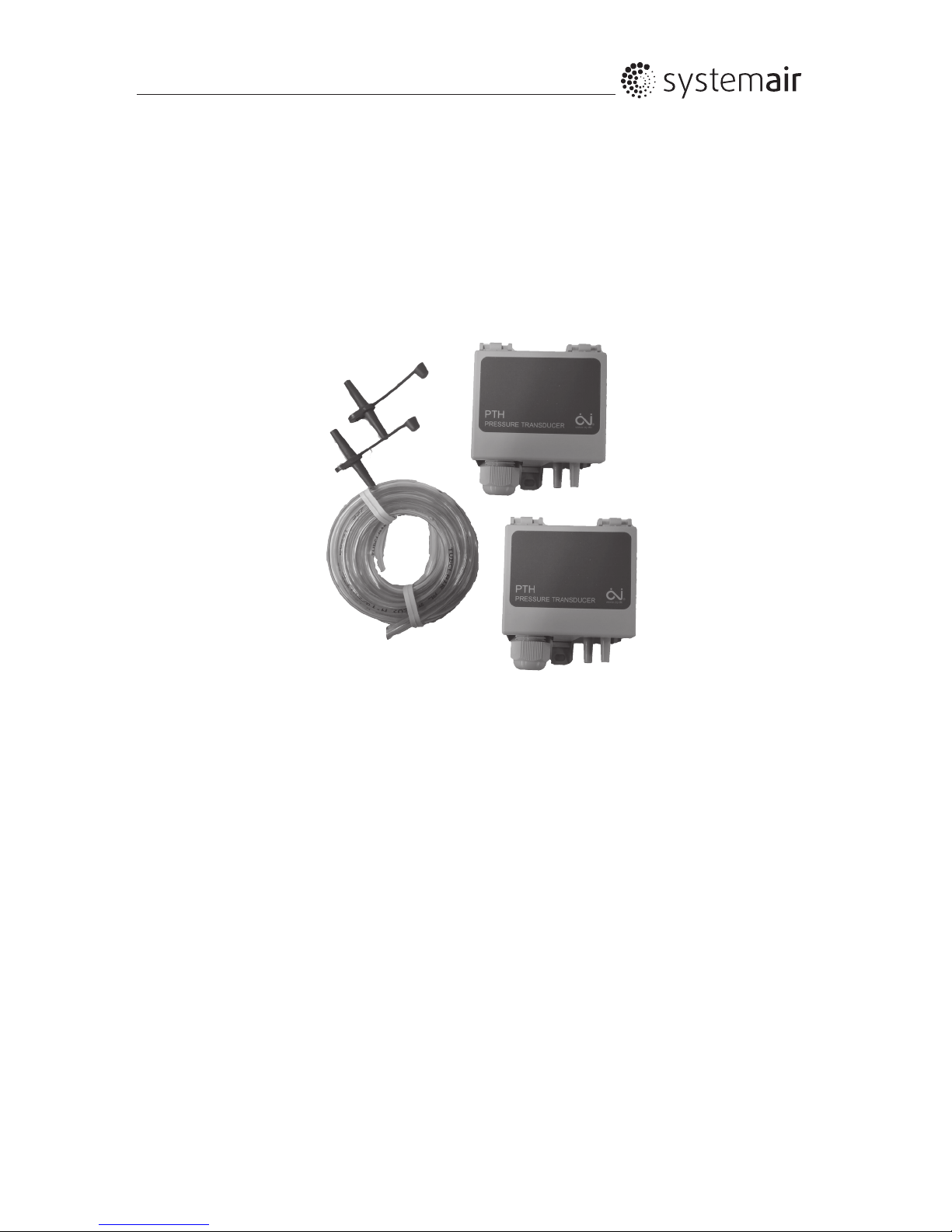
This Kit includes:
Pressure transducer (2 pcs)
Pressure tap (2 pcs)
Screw (6 pcs)
Tubing of 1m (2 pcs)
Item# : 420300
2017-11-01
Page 2
READ AND SAVE THESE INSTRUCTIONS!
Danger
• Make sure that the Main power supply to the unit is disconnected before performing any
maintenance or electrical work!
• All electrical connections must be carried out by an authorized installer and in accordance with local
rules and regulations.
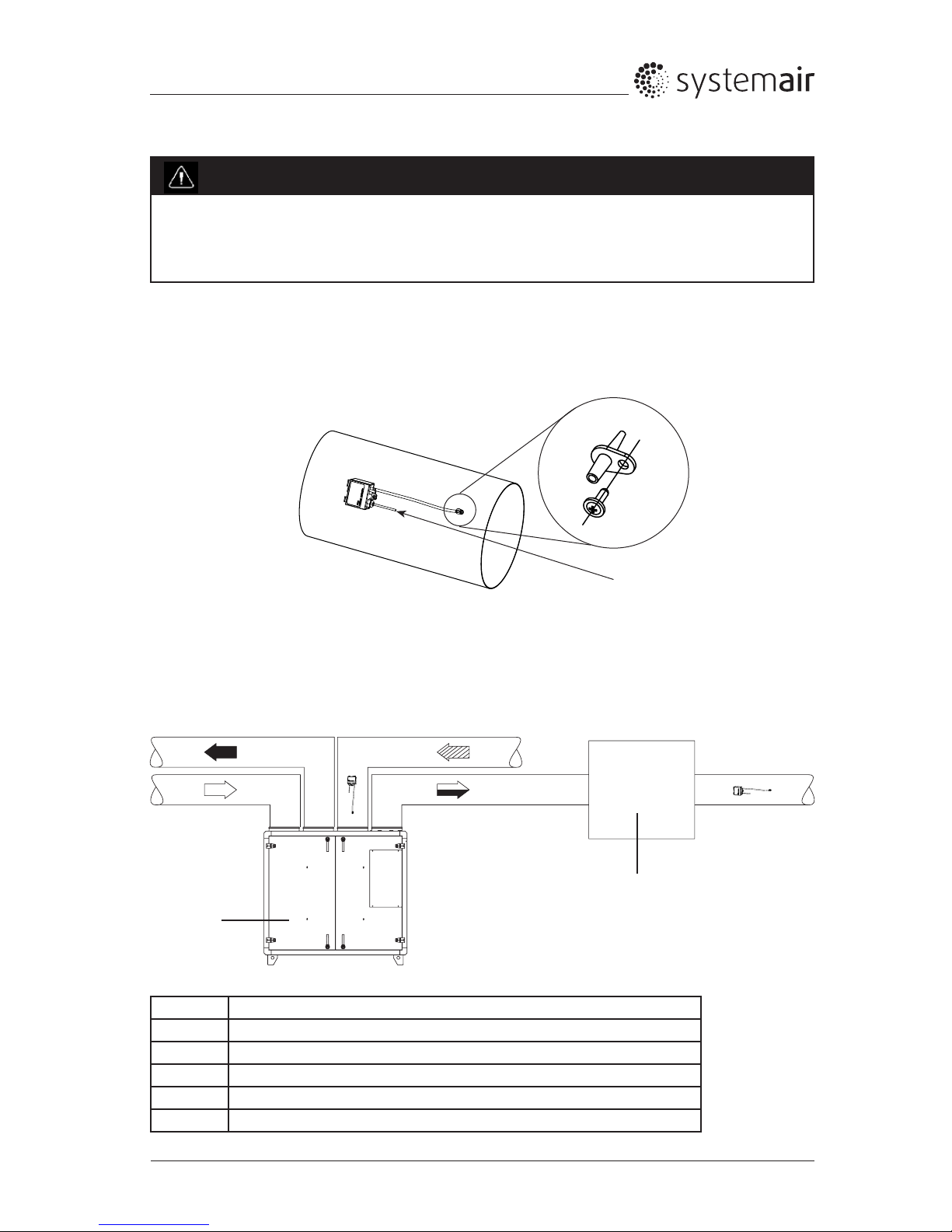
1. Locate where the pressure tap is going to be installed. The pressure tap should be 5 duct diameters
from the applicable opening of the unit or midpoint between applicable opening and rst down-stream
obstruction (bends, splits, dampers, coils, diusers, etc). Use the mounting location that allows for the
furthest distance from the unit, drill a 5/16” hole and install pressure tap.
To unit
*** If there is another AHU (i.e. DOAS, furnace, etc) in series downstream of the unit then the pressure
tap should be located downstream of the AHU as described above.
4
B
1
3
2
A
DOAS, furnace, etc
Systemair Unit
1 Outdoor Air (OA)
2 Supply Air (SA)
3 Return Air (RA)
4 Exhaust Air (EA)
A Dierential pressure transmitter & pressure tap for supply air fan
B Dierential pressure transmitter & pressure tap for exhaust air fan
Topvex Series
VAV installation Kit
2
Systemair Inc.
Page 3
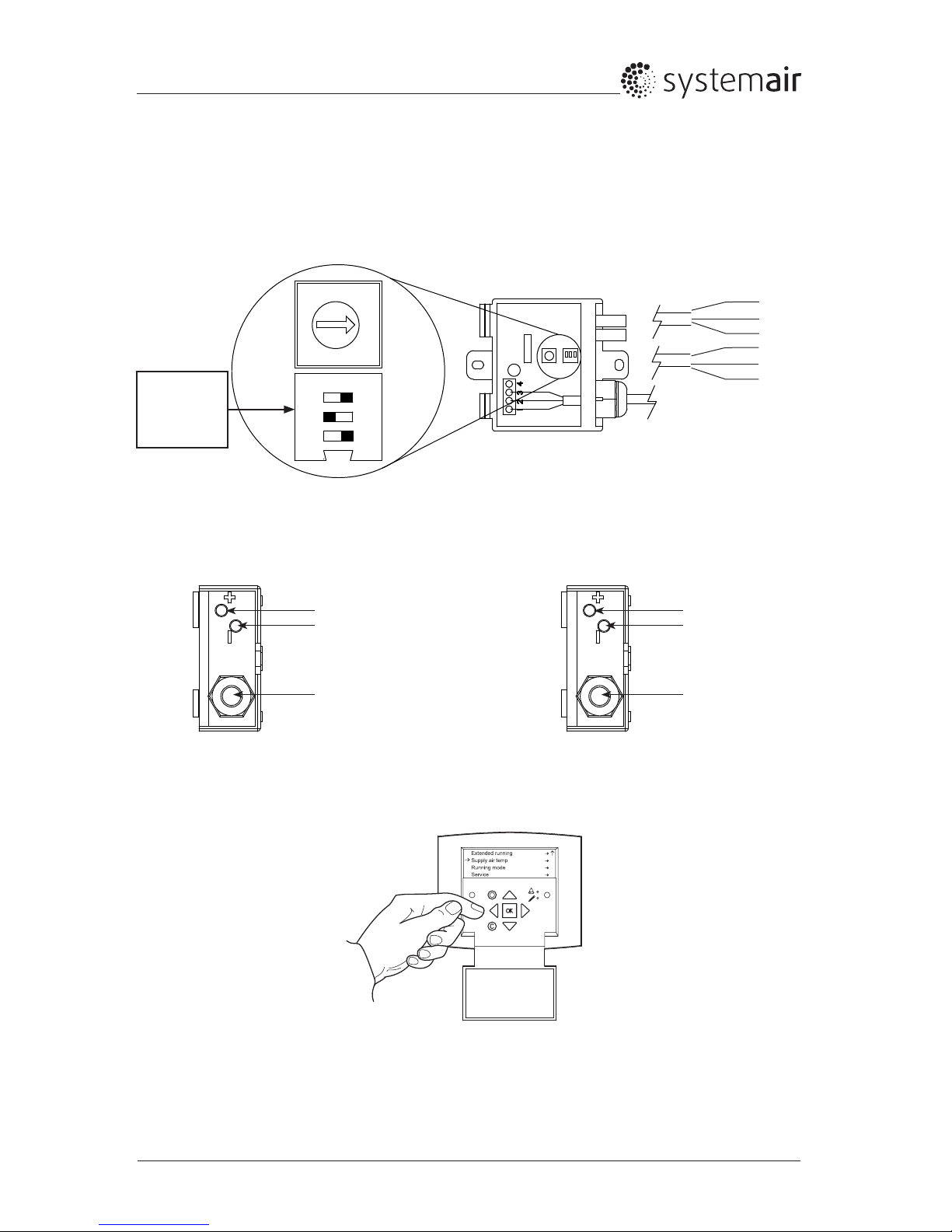
2. Mount dierential pressure transducer as close as possible to the pressure tap while still permitting
accessibility. Connect one end of tube to duct mounted pressure tap and one end to the dierential
pressure transducer. For the supply, connect it to the high side (+). For the exhaust, connect it to the
low side (-). Insure that no kinks, twists, cuts, or punctures can occur in tube.
3. Install low voltage signal / power wire connecting dierential pressure transmitter to unit. See gure
below
F
0
1
E
2
3
D
C
4
5
6
B
7
A
8
9
SupplyExhaust
TB3-40
TB3-42
TB3-10
TB3-40
TB3-41
TB3-10
1 - OFF
2 - ON
3 - OFF
ON
1 2 3
Supply Exhaust
Connect to pressure tap
Leave open to atmosphere
Signal wire to unit
Leave open to atmosphere
Connect to pressure tap
Signal wire to unit
4. Once the dierential pressure transducers have been mounted and wire back to their respective inputs on
the unit, the unit software needs to be setup for a VAV application by using the control panel and following
the procedure on page 4.
Topvex Series VAV installation Kit
3
Systemair Inc.
Page 4

1 Access rights
Go to Access Rights by using the UP/DOWN
arrow buttons. Select by pressing the RIGHT arrow
button.
Temperature
Air Control
Time settings
→Access Rights
2 Log on
Choose Log on. Select by pressing the RIGHT
arrow button.
3 Password
Enter password 1111 by pressing OK followed by
the UP/DOWN arrow buttons. Select next digit by
pressing the RIGHT arrow button. Press OK when
all 4 digits have been entered.
Go back 2 steps using the LEFT arrow button.
4 Conguration menu
Go to Conguration by using the UP/DOWN
arrow buttons. Select by pressing the RIGHT arrow
button.
→Log on
Log o
Change password
Log on
Enter password xxxx
Actual level: None
Man/auto
Settings
→Conguration
Access Rights
5 Inputs/Outputs
Go to Inputs/Outputs by using the UP/DOWN
arrow buttons. Select by pressing the RIGHT arrow
button.
6 Analog input exp3
Go to AI exp3 by using the UP/DOWN arrow
buttons. Select by pressing the RIGHT arrow
button.
*If AI exp3 does not appear in this menu, go
back 1 step using the LEFT arrow button and
proceed to step 8.
Topvex Series
→Inputs/Outputs
Control function
Fan control
Extra Sequence Y4
Topvex ####
YYYY-MM-DD HH:MM
SYSTEMI: STOPPED
SP: ACT: °F ↓
VAV installation Kit
4
Systemair Inc.
Page 5

7 Pressure A exp3
Pressure A exp3
Conrm by pressing OK button. Set Sign to
Not used by using the UP/DOWN arrow buttons.
Conrm by pressing OK twice.
Go back 1 step using the LEFT arrow button.
8 Analog input exp4
Go to AI exp4 by using the UP/DOWN arrow
buttons. Select by pressing the RIGHT arrow
button.
*If AI exp4 does not appear in this menu, go
back 1 step using the LEFT arrow button and
proceed to step 10.
9 Pressure A exp4
Conrm by pressing OK button. Set Sign to
Not used by using the UP/DOWN arrow buttons.
Conrm by pressing OK twice.
Go back 1 step using the LEFT arrow button.
Sign: Not used
Raw value: 0.0
Compensation: 0.0Pa↓
AI
AI exp4
→AI exp4
DI
Pressure A exp4
Sign: Not used
Raw value: 0.0
Compensation: 0.0Pa↓
10 Analog input
Go to UI by using the UP/DOWN arrow buttons.
Select by pressing the RIGHT arrow button.
11 EAF Pressure
Go to UI1 by using the UP/DOWN arrow buttons.
Conrm by pressing OK. Set AI Sign to EAF
pressure by using the UP/DOWN arrow buttons.
Conrm by pressing OK.twice.
12 SAF Pressure
Go to UI2 by using the UP/DOWN arrow buttons.
Conrm by pressing OK. Set AI Sign to SAF
pressure by using the UP/DOWN arrow buttons.
Conrm by pressing OK twice.
Go back 2 steps to the main menu using the
LEFT arrow button.
→UI
UI exp3
UI exp4
AO
UI1
Choose AI or DI sign
AI sign: EAF Pressure
DI sign: Not used
UI2
Choose AI or DI sign
AI sign: SAF Pressure
DI sign: Not used
Topvex Series VAV installation Kit
5
Systemair Inc.
Page 6

13 Fan Control
Inputs/Outputs
Go to Fan Control using the DOWN arrow
buttons. Select by pressing RIGHT arrow button.
14 Pressure control
Press the OK button to select Pressure
control. Press OK to conrm.
Go back 2 steps using the LEFT arrow button
15 Air Control
Go to Air control by using the UP/DOWN
arrow buttons. Select by pressing the RIGHT arrow
button
Sensor settings
Control function
→Fan control
Fan control
Pressure control
Temperature
→Air Control
Time settings
Access Rights
16 Pressure Control SAF
From this submenu, the actual supply duct
pressure measured is displayed along with the set
point for the current unit operation mode. Press the
RIGHT arrow button to access the next submenu.
17 Pressure Control SAF
From this submenu, the set points for normal
speed (1/1) and reduced speed (1/2) for the supply
air fan can be entered. Press the OK button to
access the eld, use the arrow buttons to set a
value and press OK again to save the value. Press
the LEFT arrow to return to the previous submenu.
18 Pressure Control EAF
From this submenu, press the DOWN arrow.
The actual exhaust duct pressure measured is
displayed along with the set point for the current
unit operation mode. Press the RIGHT arrow
button to access the next submenu.
Pressure control SAF
Actual: Pa
Setp: Pa
Pressure control SAF
Step 1/1: Pa
Setp 1/2: Pa
Pressure control EAF
Actual: Pa
Setp: Pa
Topvex Series
VAV installation Kit
6
Systemair Inc.
Page 7

3 Pressure Control EAF
From this submenu, the set points for normal
speed (1/1) and reduced speed (1/2) for the
exhaust air fan can be entered. Press the OK
button to access the eld, use the arrow buttons to
set a value and press OK again to save the value.
Press the LEFT arrow twice to return to the main
menu and press the UP arrow 3 times to display
the system status screen.
Pressure control EAF
Step 1/1: Pa
Setp 1/2: Pa
Topvex Series VAV installation Kit
7
Systemair Inc.
Page 8

Systemair Inc. reserves the right to make changes and improvements to the contents
of this manual without prior notice.
Systemair Inc.
50 Kanalakt Way
Bouctouche, NB
E4S3M5, Canada
Phone + 1 800 263 7081
10048 Industrial Blvd
KS, 66215
United States
Phone +1 800 263 7081
www.systemair.net
 Loading...