

SystemAir TFC 225 P, TFC 355 P, TFC 280 P, TFC 450 P, TFC 500 P Operation And Maintenance
...Page 1

Roof fans
TFC 225-560 S/P
Operation and Maintenance Instructions
Document in original language | 206434 · A006
GB
Page 2

© Copyright Systemair AB
All rights reserved
E&OE
Systemair AB reserves the rights to alter their products without notice.
This also applies to products already ordered, as long as it does not affect the previously agreed specifications.
206434 | A006
Page 3

1 EU Declaration of conformity....... . . . . . ............. . . . . . 1
2 Warnings. . . . . . .............. . . . . . . ............. . . . . . ...........2
3 Product information ....... . . . . . . . ............. . . . . . . ........3
3.1 General....... . . . . . . . ............. . . . . . . ............. . . 3
3.2 Technical data ............ . . . . . . ............. . . . . . . . .4
3.2.1 Dimensions and weight ............. . . 4
3.2.2 Performance ...... . . . . . ............. . . . . . 5
3.2.3 Wiring diagram . . . . . . . . ............ . . . . . .6
3.2.4 Residual current devices . . . ......... 10
3.3 Transportation and storage. . . . ............. . . . . 10
4 Installation.... . . . . . . ............ . . . . . . . .............. . . . . . . .. 10
4.1 Installing the fans ... . . . . . . ............. . . . . . ...... 11
4.2 Change from VAV to CAV ..... . . . . . ............. 13
4.3 K-factor ......... . . . . . . .............. . . . . . . .......... 13
4.4 Commissioning .......... . . . . . . ............. . . . . . . . 14
4.5 Alarm output . . . . . . ............. . . . . . . . ............. 14
5 Control panel......... . . . . . . ............. . . . . . . . ............. 15
5.1 Operating the control panel ............. . . . . . .. 15
6 Maintenance .............. . . . . . . .............. . . . . . ......... 18
6.1 Important ....... . . . . . . .............. . . . . . . .......... 18
6.2 Maintenance intervals ..... . . . . . . ............ . . . . 18
6.3 Cleaning the fan........ . . . . . . . ............. . . . . . .. 18
7 Troubleshooting..... . . . . . . . ............. . . . . . . ............. 19
Contents
206434 | A006
Page 4

Page 5

EU Declaration of conformity |
1 EU Declaration of conformity
Manufacturer
Systemair Sverige AB
Industrivägen 3
SE-739 30 Skinnskatteberg SWEDEN
Office: +46 222 440 00 Fax: +46 222 440 99
www.systemair.com
hereby confirms that the following products:
Roof fans TFC 225-560 S/P
(The declaration applies only to product in the condition it was delivered in and installed in the facility in accordance with the included
installation instructions. The insurance does not cover components that are added or actions carried out subsequently on the
product)
Comply with all applicable requirements in the following directives and regulations
1
Machinery Directive 2006/42/EC Ecodesign Directive 2009/125/EC
Low Voltage Directive 2014/35/EU
EMC Directive 2014/30/EU
The following harmonized standards are applied in applicable parts:
EN ISO 12100:2010
EN 13857
Safety of machinery – General principles for design – Risk assessment and risk reduction.
Safety of machinery – Safety distances to prevent hazard zones being reached by upper
327/2011 Requirements for fans
1253/2014 Requirements for ventilation units
or lower limbs.
EN 60 335-1
EN 60 335-2-80
Household and similar electrical appliances – Safety Part 1: General requirements.
Household and similar electrical appliances – Safety – Part 2-80: Particular requirements
for fans.
EN 62233
Measurement methods for electromagnetic fields of household appliances and similar
apparatus with regard to human exposure.
EN 50 106:2007
Safety of household and similar appliances – Particular rules for routine tests referring to
appliances under the scope of EN 60 335-1 and EN 60967.
EN 60529
EN 60 204-1
EN 61000-6-2
Degrees of protection provided by enclosures (IP Code).
Safety of machinery – Electrical equipment of machines – Part 1: General requirements
Electromagnetic compatibility (EMC) – Part 6-2: Generic standards – Immunity for
industrial environments.
EN 61000-6-3
Electromagnetic compatibility (EMC) – Part 6-3: Generic standards – Emission standards
for residential, commercial and light-industrial environments.
The complete technical documentation is available.
Skinnskatteberg, 09-05-2016
Mats Sándor
Technical Director
206434 | A006
Page 6
Warnings
|
2
2 Warnings
The following admonitions will be presented in the different sections of the document:
Danger
Indicates a potentially or imminently hazardous situation which, if not avoided, could result in death or
serious injury.
Warning
Indicates a potentially hazardous situation that may result in minor or moderate injuries.
Caution
Indicates a risk of damaging the product or prevent optimal operation.
Important
• This appliance can be used by children aged from 8 years and above and persons with reduced physical,
sensory or mental capabilities or lack of experience and knowledge if they have been given supervision
or instruction concerning use of the appliance in a safe way and understand the hazards involved.
• Children shall not play with the appliance. Cleaning and user maintenance shall not be made by children
without supervision.
206434 | A006
Page 7
Product information |
3 Product information
3.1 General
This installation manual concerns Roof fans TFC 225, TFC 280, TFC 355, TFC 450, TFC 500 and TFC 560 manufactured
by Systemair Sverige AB.
The S-fans are delivered with potentiometer, 0-10 V. The integrated potentiometer is factory preset to 10 V. This value
can be changed manually to obtain a different motor rpm/fan performance. Fan performance charts for this purpose
are shown in the table by voltage steps (chapter 3.2.2). An external potentiometer can be connected if necessary. If so
the internal potentiometer needs to be disconnected from the connection terminals. It is also possible to use an external pressure meter to set the desired airflow using the K-factor table (chapter 4.3).
The P-fans are regulated with a built in differential pressure and airflow controller. The fans are delivered with VAV control – Variable Air Volume but can be converted to CAV – Constant Air Volume (see chapter 4.2).
This manual consists of basic information and recommendations concerning the design, installation, start-up and operation, to ensure a proper fail-free operation of the unit. The key to proper and safe operating of the unit is to read this
manual thoroughly, use the unit according to given guidelines and follow all safety requirements.
The TFC 225-560 S/P are intended for transportation of air in air handling systems. The fans are meant for use in ducted
systems and should always be duct connected on the inlet side. No moving parts shall be accessible after installation.
TFC 225-560 S/P roof fans are adapted to continuous operation.
Roof fans are exclusively intended for extract air applications.
3
Danger
• The fans are not to be used in hazardous environments or connected to flue ducts.
• The appliance must be connected to a mains circuit breaker in the fixed installation.
• Switch power off (all-pole circuit breaker) before servicing or maintenance, and make sure the impeller
has come to standstill.
• Make sure protection grid has been installed (EN ISO 13857), no moving parts shall be accessible after
installation.
• Do not remove, short-circuit or disconnect safety accessories (i.e. motor protection, safety grille).
Warning
• The fans can have sharp edges and corners which may cause injuries. Be careful when opening the fans,
the motor assembled on the motor bracket is relatively heavy.
Caution
• Take precautions to prevent the back flow of exhaust gases from flues from other appliances installed in
the same room, which are fired by gas or other fuels.
• This appliance can be used by children aged from 8 years and above and persons with reduced physical,
sensory or mental capabilities or lack of experience and knowledge if they have been given supervision
or instruction concerning use of the appliance in a safe way and understand the hazards involved.
Children shall not play with the appliance. Cleaning and user maintenance shall not be made by children
without supervision.
206434 | A006
Page 8

| Product information
G
F
22
55
A
B
C
D
E
185
øH
4
3.2 Technical data
3.2.1 Dimensions and weight
Model
TFC 225 413 422 281 330 435 266 49 195 12,4
TFC 280 514 523 333 450 535 368 86 245 17,1
TFC 355 618 627 376 535 637 491 150 300 27,5
TFC 450 728 737 417 655 747 602 176 375 35,4
TFC 500 924 934 531 840 946 695 200 400 60,8
TFC 560 924 934 531 840 946 744 279 470 74
□A □B
C
□D
E F G øH
Weight, kg
206434 | A006
Page 9

3.2.2 Performance
0 0.1 0.2 0.3 0.4
0
200
400
600
Q [m³/s]
Ps [Pa]
0 300 600 900 1200 1440
[m³/h]
16738, 16737
4,6V
6,5V
10V
TFC 225
2,6V
0 0.2 0.4 0.6 0.8
0
100
200
300
400
500
Q [m³/s]
Ps [Pa]
0 500 1000 1500 2000 2500
[m³/h]
16853, 16852
5V
7,4V
10V
TFC 280
2,6V
0 0.4 0.8 1.2 1.6
0
250
500
750
1000
Q [m³/s]
Ps [Pa]
0 1000 2000 3000 4000 5000
[m³/h]
16745, 16744
5V
7,3V
10V
TFC 355
2,5V
0 0.5 1 1.5 2
0
200
400
600
800
Q [m³/s]
Ps [Pa]
0 2000 4000 6000
[m³/h]
16888, 16886
4,8V
7V
10V
TFC 450
2,4V
0 1 2 3
0
300
600
900
1200
Q [m³/s]
Ps [Pa]
0 2500 5000 7500 10000
[m³/h]
16894, 16893
4,6V
7V
10V
TFC 500
2,3V
0 1 2 3 4
0
300
600
900
1200
Q [m³/s]
Ps [Pa]
0 4000 8000 12000
[m³/h]
16792, 16791
4,4V
6,7V 10V
TFC 560
2,3V
Product information |
5
206434 | A006
Page 10
| Product information
Tacho
0-10V DC
Ext
RD
YE
BU
WH
1
3
2
4
BU
BN/BK
GN-YE
230V 1~
NLP
E
1
TFC 225-280 S
M
RSA
RSB
0-10V DC
Ext
RD
YE
BU
WH
BN
1
3
2
4
230V 1~
BU
BN
GN-YE
NLPE
GN-YE
WH 2
WH 1
GN-YEBUBK
BN
BU
1
TFC 355-450 S
M
3
6
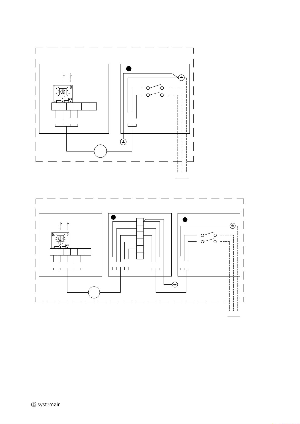
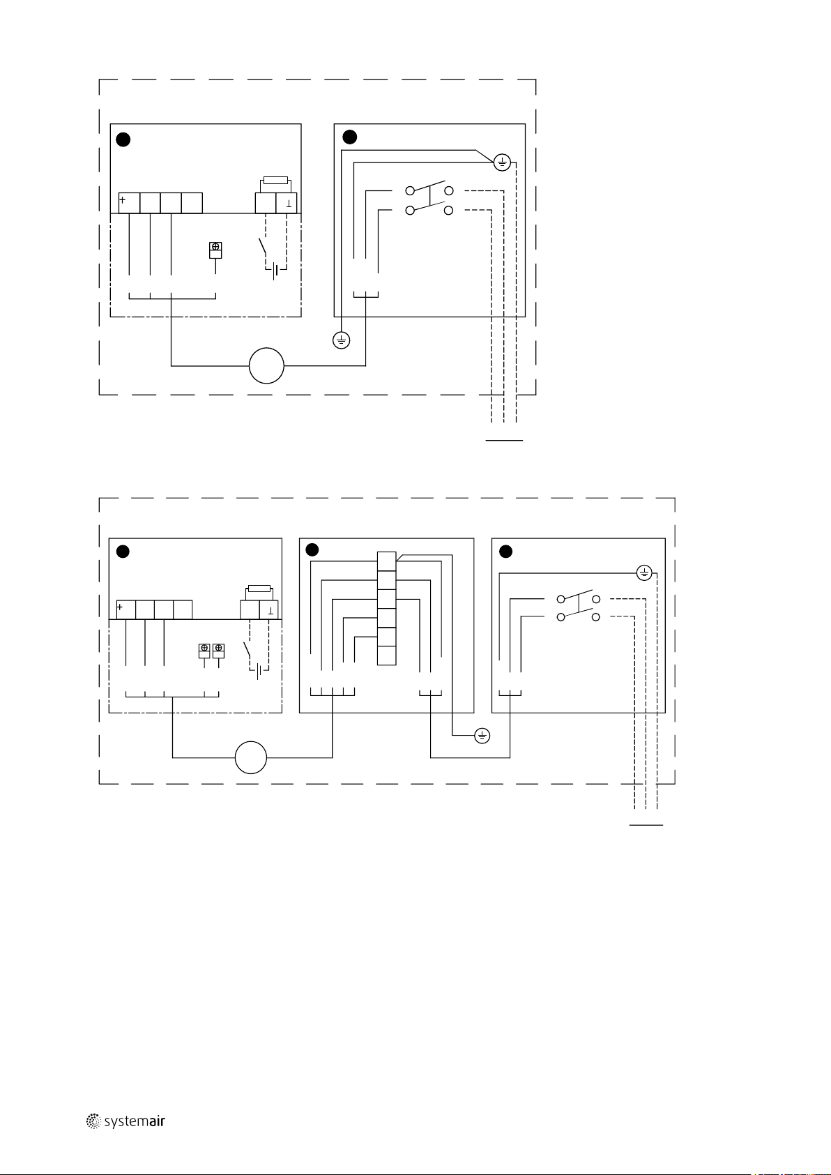
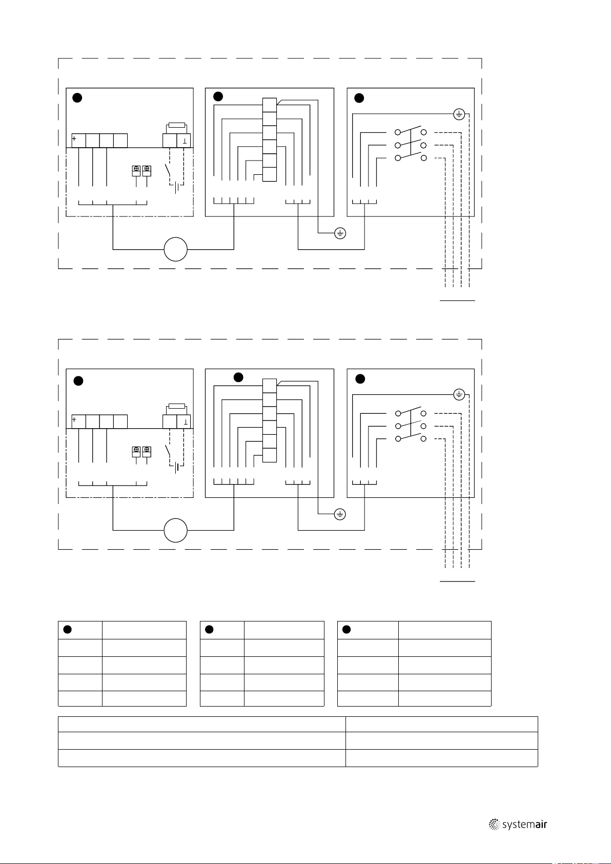
3.2.3 Wiring diagram
Modbus communication is possible from TFC 355, see wiring diagram.
206434 | A006
Page 11

Product information |
1
3
2
4
400V 3~
5
6
BK
BN
GN-YE
GY
L2L1PE
L3
GYBKBN
GN-YE
0-10V DC
Ext
RD
YE
BU
WH
BN
RSA
RSB
WH 2
WH 1
BK 3
BK 2
BK 1
GN-YE
1
TFC 500 S
M
3
1
3
2
4
400V 3~
5
6
BK
BN
GN-YE
GY
C
NC
L3L2L1
PE
L2L1PE
L3
GYBKBN
GN-YE
0-10V DC
Ext
+10V
Ain1U
GND
RSA
RSB
1
TFC 560 S
M
3
7
Ext = External
206434 | A006
Page 12
| Product information
1
3
2
4
230V 1~
RDYEBU
WH
BU
BN/BK
GN-YE
N
L
PE
Tacho
AGNDU
S
GND
1
2
TFC 225-280 P
M
10V DC
-
+
10.. .24 V DC
2( )1(+)
Ri = 4 kΩ
1
3
2
4
230V 1~
RDYEBU
WH
BN
BU
BN
GN-YE
WH 2
WH 1BUBK
GN-YE
NLPE
BUBNGN-YE
RSA
RSB
AGNDU
S
GND
1(+) 2( )
1
2
TFC 355-450 P
M
3
10V D C
10... 24 V DC
-
+
Ri = 4 kΩ
8
206434 | A006
Page 13
Product information |
1
3
2
4
400V 3~
5
6
BKBNGN-YE
GY
WH 2
WH 1
BK 3
BK 2
BK 1
GN-YE
L2L1PE
L3
GYBKBN
GN-YE
RDYEBU
WH
BN
AGNDU
S
GND
RSA
RSB
1
2
TFC 500 P
M
3
10V D C
10... 24 V DC
-
+
2( )1(+)
Ri = 4 kΩ
1
3
2
4
400V 3~
5
6
BKBNGN-YE
GY
C
NC
L3L2L1
PE
L2L1PE
L3
GYBKBN
GN-YE
+10V
Ain1U
GND
RSA
RSB
AGNDU
S
GND
1
2
TFC 560 P
M
3
10V D C
10... 24 V DC
-
+
2( )1(+)
Ri = 4 kΩ
1
2
3
9
Safety switch
RD
YE
BU
WH
Switch-over contact enables:
Voltage off
Red
Yellow
Blue
White
Voltage on
206434 | A006
Fan control
Black
NC/WH1 Alarm output
C/WH2 Normally closed
GN Green
BN Brown
GY Gray
BK
Alarm
Setpoint 1 active
Setpoint 2 active
Page 14

| Installation
10
3.2.4 Residual current devices
Only universal (type B, B+) RCD protective devices are permitted.
Like frequency inverters, RCD protective devices cannot provide personal safety while operating the device, pulse
charge currents from the capacitors in the integrated EMC filter lead to the RCD protective device triggering without
delay.
We recommend residual current devices with a trigger threshold of 300mA and delay triggering. (super-resistant, characteristic K)
3.3 Transportation and storage
All fans are packaged at the factory to withstand normal transport handling. When handling the goods use suitable lifting equipment in order to avoid damage to fans and personnel. Avoid blows and shock loads. Store the fans in a dry
place protected from weather and dirt until final installation.
Warning
• The unit is heavy. Be careful during transport and installation. Risk of injury through pinching. Use
protective clothing.
• Do not lift the fans by the connecting cable, connection box, motor bracket, impeller or inlet cone.
4 Installation
Danger
• Make sure that the mains supply to the unit is disconnected before performing any maintenance or
electrical work!
• All electrical connections must be carried out by an authorized installer and in accordance with local rules
and regulations.
Warning
• The units electrical connection to the mains supply must be preceded by an all pole circuit breaker with a
minimum 3 mm gap.
• Do not lift the fans by the connecting cable, connection box, motor bracket, impeller or inlet cone.
• Do not block or cover the drainage gap around the bottom of the fan.
The fan should be installed horizontally. Make sure the assembly of the fan is firmly fixed and stable. The fans must be
installed to ensure that service and maintenance can be performed easily and safely. Disturbing noise can be reduced
by installing silencers (available as an accessory). Electrical connections are made according to the wiring diagram in
the terminal box, markings on terminal blocks or on cable. All 3 phase fans are delivered from factory in 400 V 3~
connection.
206434 | A006
Page 15

4.1 Installing the fans
Installation |
11
Figure 1
Loosen the screws to open the lid to reach the motor.
Unscrew the two screws to open the lid to the electrical
compartment.
Figure 2
Connect the mains supply to the lockable safety switch
(1). Image show S-controller (2).
The hinges on the hatch to the electrical compartment
prevents the hatch from falling down.
Figure 3
Possible to mount the TFC with suitable roof curb
(optional), using the holes in the bottom of the fan (3).
206434 | A006
Figure 4
TFC mounted on roof curb.
Page 16

| Installation
4
5
12
Figure 5
Mains supply (4) can be run through the cable glands beside the electrical compartment or inside a roof curb, if used.
Note:
Don’t cover this gap (5). It is for drainage if water enters the fan.
206434 | A006
Page 17

Installation |
k ·
q =
p
4.2 Change from VAV to CAV
TFC 225 -TFC 560 are delivered as VAV- fans. The tubing is connected to - (minus) inlet on the controller.
All fans are also prepared with tubing for CAV (Constant air volume). The tubing is attached along the side of the casing
and loosely inserted in the electrical compartment. Change the function to CAV by replacing the connection to the controller, the tubing from the bottom of the fan (1) to + (plus) inlet and the tubing from the cone (2) to - (minus).
The tubing from the cone is labelled with blue tape.
13
In BASE SETUP 5.01 in table 1, set the K-factor (see chapter 4.3). In SETTINGS, adjust the airflow for Setpoint 1, Setpoint
2 and Pband (nominal airflow x 2 recommended).
4.3 K-factor
Use the following equation to calculate the requested setting:
q = airflow [m3/h]
k = k-factor
p= tuning pressure [Pa]
Model K-factor
TFC 225 57
TFC 280 79
TFC 355 134
TFC 450 212
TFC 500 289
TFC 560 554
206434 | A006
Page 18

| Installation
14
4.4 Commissioning
Danger
• All electrical connections must be carried out by an authorized installer and in accordance with local rules
and regulations.
Before initial operation, check the following:
• Electrical connection has been properly completed.
• Protective earth has been connected.
• Safety devices in place (protection grid).
• Leftover installation materials and foreign materials have been removed from the casing.
Testing the installation:
• Adjustment may be required in the electrical compartment during test (i.e. changing of the potentiometer), however
during operation the lid must be closed.
When putting into operation, check the following:
• Connection data corresponds to the specifications on the nameplate: Maximum voltage +6%, -10%, according to IEC
38. Rated current must not be exceeded with more than 5% at rated voltage.
• The direction of rotation should correspond to direction-of-rotation arrow (3 phase).
• Smoothness of motor operation, (no abnormal noises).
Sound levels exceeding 70 dB(A) may occur depending on size (see www.systemair.com for detailed information).
4.5 Alarm output
The fan motor has built in protection for locked rotor, which implies that the motor tries to restart with a pre-programmed interval whenever it senses that the rotor is standing still. When the blockage is removed the fan will start up
by itself without any further measures. At high motor temperatures the current will be cut from the motor. It can then
only be restarted by manually disconnecting the mains supply to the fan for couple of minutes.
TFC 225 and TFC 280 has Tacho output
The tacho output is an open collector output. Connect a pull up resistor to a DC voltage – make sure that the current
does not exceed 10mA.
206434 | A006
Page 19

5 Control panel
5.1 Operating the control panel
Multipurpose LC display and keyboard
Control panel |
15
100 Pa
∆p
P
▼
▲
▼+▲
Messages on the display
!
100 Pa
∆p
Selection of the menu group (e.g. BASE SETUP) to the right through the ▼-key, to the left through the ▲-key. You can
go to the menu items in the menu groups (e.g. mode) by using the P key. Use the arrow keys to move up and down
within the menu group. To make adjustments, press the P key after selecting the menu item. If the previously set value
starts to ash, it can be adjusted with the ▼ + ▲ keys and then saved with the P key. To exit the menu without making
any changes, use the “Esc” short-key, i.e., the originally set values remain.
For more detailed information see table 1.
Display after turning on the voltage supply. Switch over between
actual value display and “INFO” with the key shortcut for Escape
(Esc = ▼+▲)
Display show the actual and desired values
Display show menu text
Program key and open menu
Menu selection, reduce value
Menu selection, increase value
ESC-key combination, Escape = leave menu
Exceeding measuring range
Moon symbol = Adjustment for Setpoint 2 active
Info
INFO
P ↓↑ Esc P ↓↑ Esc P ↓↑ Esc
100 Pa
∆p
▲▼ ▲▼ ▲▼
100 Pa
Setpoint 1
▲▼ ▲▼ ▲▼
▼
▲
SETTINGS
100 Pa
Setpoint 1
100 Pa
Setpoint 2
▼
▲
BASE SETUP
4.01
Mode
1:metric
Units
206434 | A006
Page 20

| Control panel
16
Select operation mode
Marked area indicates factory setting.
Mode
4.00
Function
Pressure sensor output 0...10 V proportional to measuring range.
4.01 Factory preset
Pressure controller (PID): Output 0...10 V depending on adjusted setpoint and
measured actual value.
5.00
Air volume sensor: Output 0...10 V proportional to measuring range
(depending on setting for K-factor).
5.01
Air volume controller (PID): Output 0...10 V depending on adjusted setpoint
and measured actual value
Table 1 Parameter table
Parameter
Display/Factory
setting
Mode
4.00 4.01 5.00 5.01
INFO
∆p
qV
Setpoint 1
Range qV
0 Pa 0 Pa
- -
-
100 Pa
- -
- -
3
0 m
/h 0 m3/h Display actual
-
2371 m
3
/h 2371 m3/h Air volume
1185 m
Uout 0.0 V 9.9 V 0.0 V 9.9 V
UNIcon 1.00 1.00 1.00 1.00
∆p
- -
0 Pa 0 Pa
Function
Mode
Information
Different actual
value for
differential
pressure
value for airflow
3
/h Display active
Setpoint
measuring range
depending on
sensor
measuring range
and K-factor
Magnitude of the
output voltage
0...10 V
Software version
Display actual
value for volume
measurement
206434 | A006
Page 21

Control panel |
17
Setpoint 1
Setpont 2
SETTING 4.01 + 5.01
-
-
100 Pa
200 Pa
-
-
1185 m
1185 m
3
h
3
h
Setting
Setpoint 1
Setpoint 2
(Active if voltage
at terminals 1, 2)
Pband
Min. Uout
-
-
250 Pa
0.0 V
-
-
1185 m
0.0 V Min output
3
h Pband1,
voltage:
0.0...10.0 V
(priority over
“Max. Uout”)
Parameter
Max. Uout
Display/factory setting
-
10.0 V
-
10.0 V Max. output
Function
voltage:
10.0...0.0 V
1
Setting range 4.01: 0...100 % sensor measuring range, 5.01: 0...Max. Range qV (depending on K-factor and sensor measuring
range).
2
Small value = quick regulation, great value = slow regulation, high stability.
BASE SETUP Base setup
Mode
Units
4.00 4.01 5.00 5.01
metric: Pa, m
3
/h, K-factor
Mode
SI units or
Imperial units
(US)
Measuring range 1: 0...1000 Pa
2: 0...500 Pa
3: 0...300 Pa
PCA1000D2
Adjustable
measuring range
4: 0...200 Pa
K-factor
(K-factor US)
- -
75 75
Nozzle
coefficient (Kfactor) see
chapter 4.3
Autozero OFF => ON
Automatic “0”
offset
Offset
0 Pa
Sensor offset
(automatically
when
“Autozero”)
Setting range:
+/- 1000 Pa
1
1
2
,
2
206434 | A006
Page 22

Maintenance
|
18
6 Maintenance
6.1 Important
Danger
• Make sure that the mains supply to the unit is disconnected before performing any maintenance or
electrical work!
• Fan impeller has come to a complete standstill.
• Should the supply cable be damaged, it must be replaced by the manufacturer, its service agent or
similarly qualified persons in order to avoid a hazard
• The unit is heavy. Be careful during transport and installation. Risk of injury through pinching. Use
protective clothing.
• Do not lift the fans by the connecting cable, connection box, motor bracket, impeller or inlet cone.
6.2 Maintenance intervals
The fan should be cleaned when necessary, at least once a year to avoid imbalance and unnecessary damage to the
bearings. The fan bearings are maintenance free and should only be replaced if damaged. Do not use a high-pressure
cleaner (steam jet) when cleaning the fan. Ensure that the fan impeller's balance weights are not moved or the fan impeller distorted. Listen for abnormal operating noise.
6.3 Cleaning the fan
Warning
• Make sure that the mains supply to the unit is disconnected before performing any maintenance or
electrical work!
• Fan impeller has come to a complete standstill.
• The unit is heavy. Make sure that the motor bracket attach to the lock to prevent the motor to fall down
during maintenance.
Danger
• Make sure that the motor does not fall down.
Caution
• Beware of sharp edges during maintenance, use protective gloves. Risk of injury through pinching.
206434 | A006
Page 23

Troubleshooting |
Loosen the M5 screws to open the lid (chapter 4.1.)
Unscrew the motor bracket's two screws. Lift the motor up by holding the motor bracket's handle,
keep fingers away from the back of the hinge. Make sure
that the motor bracket attach to the lock to prevent the
motor from falling down during maintenance.
After maintenance, release the lock, using the handle to
bring the motor down. Fasten the motor bracket with the
screws.
19
Note:
TFC 225 and TFC 280 has no handle, hold the
motor bracket to lift the motor.
7 Troubleshooting
The following applies in case the fan has stopped:
• Try to restart the fan by cutting the power a couple of minutes.
• Ensure that the impeller is not locked. Disconnect the power supply, remove any obstacles. Check that the fan starts
after reconnecting the current. Should the fan not start please contact your place of purchase.
206434 | A006
Page 24

Systemair Sverige AB
Industrivägen 3
SE-739 30 Skinnskatteberg, Sweden
Phone +46 222 440 00
Fax +46 222 440 99
www.systemair.com
Roof fans · Operation and Maintenance Instructions · 206434 · en_GB · 21-11-2017 · A006
 Loading...