

Page 1
TCA 150D
part. no. 32186
Control module for temperature
Operating Instructions
Software version: D2033A from Version 1.00
L-BAL-E119-GB 1318 Index 002 Part.-No. 00163357-GB
english
Page 2

Content
1 General notes . . . . . . . . . . . . . . . . . . . . . . . . . . . . . . . . . . . . . . . . . . . . 4
1.1 Structure of the operating instructions . . . . . . . . . . . . . . . . . . . . 4
1.2 Target group . . . . . . . . . . . . . . . . . . . . . . . . . . . . . . . . . . . . . . . . 4
1.3 Exclusion of liability . . . . . . . . . . . . . . . . . . . . . . . . . . . . . . . . . . 4
1.4 Copyright . . . . . . . . . . . . . . . . . . . . . . . . . . . . . . . . . . . . . . . . . . 4
2 Safety instructions . . . . . . . . . . . . . . . . . . . . . . . . . . . . . . . . . . . . . . . . 4
3 Product overview . . . . . . . . . . . . . . . . . . . . . . . . . . . . . . . . . . . . . . . . . 5
3.1 Operational area . . . . . . . . . . . . . . . . . . . . . . . . . . . . . . . . . . . . . 5
3.2 Function . . . . . . . . . . . . . . . . . . . . . . . . . . . . . . . . . . . . . . . . . . . 5
3.3 Storage . . . . . . . . . . . . . . . . . . . . . . . . . . . . . . . . . . . . . . . . . . . . 5
3.4 Disposal / recycling . . . . . . . . . . . . . . . . . . . . . . . . . . . . . . . . . . 5
4 Mounting . . . . . . . . . . . . . . . . . . . . . . . . . . . . . . . . . . . . . . . . . . . . . . . . 6
4.1 General notes . . . . . . . . . . . . . . . . . . . . . . . . . . . . . . . . . . . . . . . 6
4.2 Installation location for agriculture . . . . . . . . . . . . . . . . . . . . . . . 6
4.3 Temperature influences during commissioning . . . . . . . . . . . . . . 6
5 Electrical installation . . . . . . . . . . . . . . . . . . . . . . . . . . . . . . . . . . . . . . 7
5.1 Safety precautions . . . . . . . . . . . . . . . . . . . . . . . . . . . . . . . . . . . 7
5.2 EMC-compatible installation of control lines . . . . . . . . . . . . . . . . 7
5.3 Connection Voltage supply . . . . . . . . . . . . . . . . . . . . . . . . . . . . . 7
5.4 Connection of sensor . . . . . . . . . . . . . . . . . . . . . . . . . . . . . . . . . 7
5.5 Output voltage 0 - 10 V . . . . . . . . . . . . . . . . . . . . . . . . . . . . . . . 8
5.6 Input for switch over Setpoint 1 / Setpoint 2 . . . . . . . . . . . . . . . . 8
6 Device construction . . . . . . . . . . . . . . . . . . . . . . . . . . . . . . . . . . . . . . . 8
7 Programming . . . . . . . . . . . . . . . . . . . . . . . . . . . . . . . . . . . . . . . . . . . . 9
7.1 Select operation mode . . . . . . . . . . . . . . . . . . . . . . . . . . . . . . . . 9
7.2 Menu structure . . . . . . . . . . . . . . . . . . . . . . . . . . . . . . . . . . . . . . 9
7.3 Menues of operating modes . . . . . . . . . . . . . . . . . . . . . . . . . . . . 10
7.4 Characteristic curve temperature sensor 2.00 . . . . . . . . . . . . . . 12
7.5 Temperature controller
2.01 . . . . . . . . . . . . . . . . . . . . . . . . . . . . 12
8 Start-up . . . . . . . . . . . . . . . . . . . . . . . . . . . . . . . . . . . . . . . . . . . . . . . . 13
8.1 Procedure . . . . . . . . . . . . . . . . . . . . . . . . . . . . . . . . . . . . . . . . . . 13
Operating Instructions TCA 150D
L-BAL-E119-GB 1318 Index 002 Part.-No. 00163357-GB
2/17
Page 3

9 Enclosure . . . . . . . . . . . . . . . . . . . . . . . . . . . . . . . . . . . . . . . . . . . . . . . 14
9.1 Technical data . . . . . . . . . . . . . . . . . . . . . . . . . . . . . . . . . . . . . . 14
9.2 Connection diagram . . . . . . . . . . . . . . . . . . . . . . . . . . . . . . . . . . 15
9.3 Dimensions [mm] . . . . . . . . . . . . . . . . . . . . . . . . . . . . . . . . . . . . 16
9.4 Manufacturer reference . . . . . . . . . . . . . . . . . . . . . . . . . . . . . . . 17
Operating Instructions TCA 150D
L-BAL-E119-GB 1318 Index 002 Part.-No. 00163357-GB
3/17
Page 4

1 General notes
1.1 Structure of the operating instructions
Before installation and start-up, read this manual carefully to ensure correct use!
We emphasize that these operating instructions apply to specific units only, and are in
no way valid for the complete system!
Use these operating instructions to work safely with and on the device. They contain
safety instructions that must be complied with as well as information that is required for
failure-free operation of the device.
Keep these operating insturctions together with the device. It must be ensured that all
persons that are to work on the device can refer to the operating instructions at any time.
1.2 Target group
The operating instructions address persons entrusted with planning, installation, commissioning and maintenance and servicing and who have the corresponding qualifications and skills for their job.
1.3 Exclusion of liability
To allow for future developments, construction methods and technical data given are
subject to alteration. We do not accept any liability for possible errors or omissions in the
information contained in data, illustrations or drawings provided.
We accept no liability for damage caused by misuse, incorrect use, improper use or as a
consequence of unauthorized repairs or modifications.
1.4 Copyright
These operating instructions contain copyright protected information. The operating
instructions may be neither completely nor partially photocopied, reproduced, translated
or put on data medium without previous explicit consent. Infringements are liable for
damages. All rights reserved, including those that arise through patent issue or registration on a utility model.
2 Safety instructions
•
Mounting, electrical connection, and start-up operation may only be carried out by
an electrical specialist in accordance with electrotechnical regulations (e.g. DIN
EN 50110 or DIN EN 60204)!
•
Persons entrusted with the planning, installation, commissioning and maintenance
and servicing in connection with the device must have the corresponding qualifications and skills for these jobs. In addition, they must be knowledgeable about
the safety regulations, EU directives, rules for the prevention of accidents and the
corresponding national as well as regional and in-house regulations.
Operating Instructions TCA 150D General notes
L-BAL-E119-GB 1318 Index 002 Part.-No. 00163357-GB
4/17
Page 5

•
The equipment is to be used solely for the purposes specified and confirmed in
the order. Other uses which do not coincide with, or which exceed those specified
will be deemed unauthorised unless contractually agreed. Damages resulting
from such unauthorised uses will not be the liability of the manufacturer. The user
will assume sole liability.
•
It is strictly forbidden for work to be carried out on any components while they are
connected to live voltage.
•
The safe isolation from the supply must be checked using a two-pole voltage
detector.
•
The owner is obliged to ensure that the device are operated in perfect working
order only.
•
Inspect electrical equipment periodically: retighten loose connections – immediately replace damaged lines and cables.
•
Never clean electrical equipment with water or similar liquids.
•
A separate fault and performance monitoring-system with an alarm signal function
is necessary in order to prevent personal injuries and material damages during
malfunctions and in case the device fails. Substitute operation must be taken into
consideration!
3 Product overview
3.1 Operational area
Temperature control for e.g.: extraction systems, warm-air heaters, air curtain installations, liquid-cooling, chillers.
Controlled output (0 - 10 V) e.g. for activating a speed controller for fans.
Fans with integrated controller and input 0 - 10 V can be activated directly.
3.2 Function
The measured actual value at the sensor is compared with the adjusted target value.
Output voltage and thus fan speed is controlled automatically depending on the adjusted
parameters.
Alternatively the device can be operated as temperature sensor. Output 0 - 10 V in this
mode proportional to the adjusted measuring range (max. -50...150 °C).
3.3 Storage
•
The device must be stored in its original packaging in a dry and weather-proof
room.
•
Avoid exposure to extreme heat and cold.
•
Avoid over-long storage periods (we recommend a maximum of one year).
3.4 Disposal / recycling
Disposal must be carried out professionally and environmentally friendly in accordance
with the legal stipulations.
Operating Instructions TCA 150D Product overview
L-BAL-E119-GB 1318 Index 002 Part.-No. 00163357-GB
5/17
Page 6

4 Mounting
4.1 General notes
Attention!
The following points must be complied with during the mechanical installation to avoid
causing a defect in the device due to assembly errors or environmental influences:
•
Before installation remove the device from the packing and check for any possible
shipping damage!
•
Assemble the device on a clean and stable base. Do not distort during assembly!
Use the appropriate mounting devices for proper installation of the unit!
•
Do not mount equipment on vibrating base!
•
When mounted onto lightweight walls, there must be no impermissibly high
vibrations or shock loads. Any banging shut of doors that are integrated into these
lightweight walls, can result in extremely high shock loads. Therefore, we advise
you to decouple the devices from the wall.
•
Do not allow drilling chips, screws and other foreign bodies to reach the device
interior!
•
The device should be installed in a location where it will not be disturbed, but at
the same time can be easily accessed!
•
Any cable ducts openings not used must be sealed!
•
Care must be taken to avoid direct radiation from the sun!
•
The device is designed for vertical installation (cable inlet down). A horizontal or
reclined installation is only permissible after technical release of the manufacturer!
4.2 Installation location for agriculture
In order to avoid damage caused by ammoniac vapours, the controller shall not be
installed in the stable, but rather in an outhouse wherever possible.
4.3 Temperature influences during commissioning
Avoid condensation in the controller and functional faults attributable to condensation by
storing the controller at room temperature!
Operating Instructions TCA 150D Mounting
L-BAL-E119-GB 1318 Index 002 Part.-No. 00163357-GB
6/17
Page 7
5 Electrical installation
5.1 Safety precautions
Danger due to electric current
•
Work on electric components may only be carried out by trained electricians or by
persons instructed in electricity under the supervision of an electrician in accordance with electrical engineering regulations.
•
The programming of the equipment takes place with switched on supply voltage
by opened cover and voltage for change-over Setpoint 1/2. Use power supplies
which guarantee reliable electrical isolation of the operating voltage as per IEC/DIN EN 60204-1. Consider also the general requirements for PELV circuits in
accordance with IEC/DIN EN 60204-1.
•
Inspect electrical equipment periodically: retighten loose connections – immediately replace damaged lines and cables.
•
Never clean electrical equipment with water or similar liquids.
Information
The respective connections are represented in the enclosure of this manual (
Connection diagram)!
5.2 EMC-compatible installation of control lines
Pay attention to maintain sufficient distance from powerlines and motor wires to prevent
interferences. The control cable may not be longer than 30 m. Screened control cables
must be used when the cable length is longer than 20 m!
5.3 Connection Voltage supply
Connection Voltage supply at terminals: “+Ub” and “GND”. Here, it must be strictly
observed that the mains voltage lies within the allowable tolerance specifications (
Technical data and nameplate affixed to the side).
5.4 Connection of sensor
Connection of temperature sensor for measuring actual value (not in scope of delivery)
to terminals “TF”. It is possible to connect sensors of series “TF..” (KTY81-210) or
PT1000 temperature sensors. It must be paid attention to no polarity.
For a high interference immunity a capacitor must be connected directly to the sensor (1
nF parallel). With temperature sensors type TF.. (KTY81-210) a capacitor is integrated.
Attention!
Never apply line voltage to analog inputs!
Operating Instructions TCA 150D Electrical installation
L-BAL-E119-GB 1318 Index 002 Part.-No. 00163357-GB
7/17
Page 8

5.5 Output voltage 0 - 10 V
Connection to Terminals “A” - “GND” (I
max
Technical data).
It is not permissible to connect outputs of several devices to each other!
5.6 Input for switch over Setpoint 1 / Setpoint 2
Via voltage at terminals “1” and “2” (10... 24 V DC) a switchover between Setpoint 1 and
Setpoint 2 is possible (note polarity
connection diagram).
20.0 °C
Setpoint 1
None Voltage at terminals “1” and “2” = adjustment for Setpoint1 active.
15.0 °C C
Setpoint 2
Voltage at terminals “1” and “2” = adjustment for Setpoint 2 active.
The active Setpoint is indicated in the menu INFO, an active “Setpoint 2” is signalized by
the moon symbol.
6 Device construction
Screw off the hinged cover to proceed with electrical connection and programming.
Subsequently close carefully!
+Ub
GND A GND
P
05.05.2010
v_ctg_bedien.vsd
!
D
27.5 °C
Actual Value
TF
TF
1
2
D
LC-Display
Moon symbol = Adjustment for Setpoint 2
active
! = Exceeding measuring range (sensor in-
terruption / sensor short-circuit)
+Ub / GND Voltage supply
A / GND Output signal 0 - 10 V
TF / TF
Connection temperature sensor (KTY81210 or PT1000)
1 / 2
Voltage input for switch over Setpoint 1 /
Setpoint 2
Multipurpose LC display and internal keyboard
27.5 °C
Actual Value
Text line 1 with 16 figures for display of actual and desired values
Text line 2 with 16 figures for display of menu text
P ▼ ▲
P Program key and open menu
▼ Menu selection, reduce value
▲ Menu selection, increase value
▼ + ▲ ESC-key combination, Escape = leave menu
Operating Instructions TCA 150D Device construction
L-BAL-E119-GB 1318 Index 002 Part.-No. 00163357-GB
8/17
Page 9

7 Programming
7.1 Select operation mode
Information
Simple installation is possible through the selection of the preprogrammed mode of
operation.
This determines the basic function of the device, factory set
2.01 .
Mode Function
2.00
Temperature sensor: output 0...10 V proportional to measuring range
2.01
Temperature controller (P): output 0...10 V depending on adjusted Setpoint an measured
actual value (Factory setting)
7.2 Menu structure
27.5 °C
Actual Value
Display after turning on the voltage supply.
Switch over between actual value display and “INFO” with
the key shortcut for Escape (ESC = ▼ + ▲).
INFO
Example for Mode
2.01 (Factory setting)
INFO
▼
▲
SETTING
▼
▲
BASE SETUP
P↓ ↑ ESC P↓ ↑ ESC P↓ ↑ ESC
20.0 °C
Actual Value
20 °C
Setpoint 1
2.01
Mode
▲ ▼ ▲ ▼ ▲ ▼
20 °C
Setpoint 1
15 °C
Setpoint 2
KTY81-210
Sensortype
▲ ▼ ▲ ▼ ▲ ▼
0.0 V
Uout
5.0 K
Pband
0.0 K
Offset
▲ ▼ ▲ ▼ ▲ ▼
2058 Ω
Resistor
0.0 V
Min. Uout
OFF
MSCO
▲ ▼ ▲ ▼ ▲ ▼
0.08
UNIcon
10.0 V
Max. Uout
ON
Value>Set = n+
Selection of the menu group (e.g. BASE SETUP) to the right through the ▼-key, to the
left through the ▲-key.
Operating Instructions TCA 150D Programming
L-BAL-E119-GB 1318 Index 002 Part.-No. 00163357-GB
9/17
Page 10

You can go to the menu items in the menu groups (e.g. mode) by using the P key. Use
the arrow keys to move up and down within the menu group.
To make adjustments, press the P key after selecting the menu item. If the previously set
value starts to flash, it can be adjusted with the ▼ + ▲ keys and then saved with the P
key. To exit the menu without making any changes, use the “Esc” short-key, i.e., the
originally set values remain.
Reprogramming Mode
2.01 to 2.00 in “BASE SETUP”
1 2 3
4
5 6 7
2.01
Mode
P
«2.01»
Mode
▲
«2.00»
Mode
P
2.00
Mode
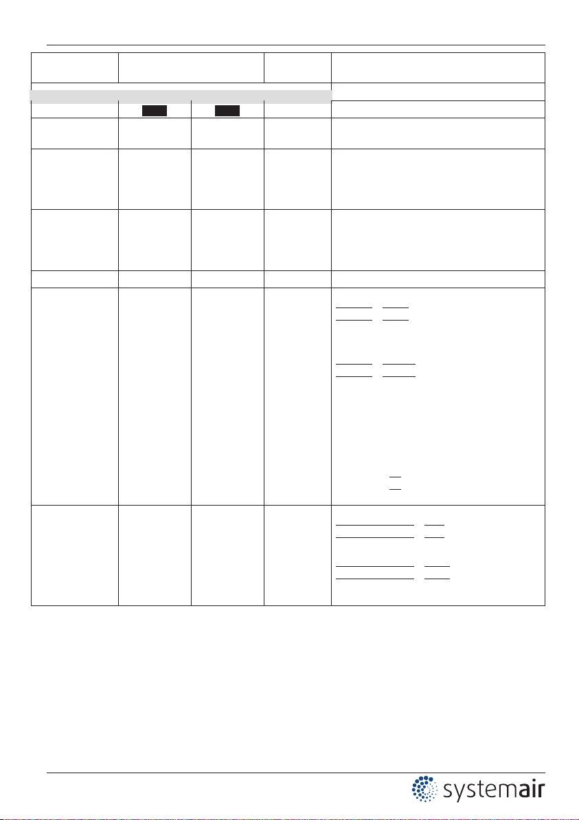
7.3 Menues of operating modes
Parameter Factory setting User Set-
ting
Function
Mode
2.00 2.01 Mode
INFO
Actual Value 27.1 °C 27.1 °C Display actual temperature
Setpoint 1 - 20.0 °C Display active Setpoint
Uout 5.0 V 5.0 V Magnitude of the output voltage 0...10 V
Resistor 2049 Ω 2049 Ω
current resistance value of the temperature
sensor
UNIcon 1.00 1.00 software version
SETTING
Setpoint 1 - 20.0 °C
Setpoint1
Setting range: -50.0...+150.0 °C
Factory setting: 20.0 °C
Setpoint 2 - 15.0 °C
Setpoint 2 active, if voltage at terminals 1, 2
Setting range: -50.0...+150.0 °C
Factory setting: 15.0 °C
Pband -
5.0 K
Pband
Setting range: 1.0...50.0 K
Factory setting: 5.0 K
Min. Uout 0.0 V 0.0 V Setting minimal output voltage
Max. Uout 10.0 V 10.0 V Setting maximal output voltage
Operating Instructions TCA 150D Programming
L-BAL-E119-GB 1318 Index 002 Part.-No. 00163357-GB
10/17
Page 11
Parameter Factory setting User Set-
ting
Function
BASE SETUP
Mode
2.00 2.01 Mode selection
Sensortype KTY81-210 KTY81-210
Setting type of sensor: KTY81-210 or
PT1000
Range min. Temperature
-50 °C -
Setting measuring range, minimum temperature value
Setting range: -50...150 °C
Factory setting: -50 °C
Range max.
Temperature
150 °C -
Setting measuring range, maximum temperature value
Setting range: 150...-50 °C
Factory setting: 150 °C
Offset 0.0 K 0.0 K Sensor offset
MSCO - OFF
Minimum speed cut off
|
MSCO|: |OFF| (factory setting)
If “Min. Uout” is adjusted (e.g. 2.0 V), than
no diconnection of the output takes place
(does not go under “Min. Uout)”.
|
MSCO|: |-2.0 K| (example)
It takes place a disconnection from Setting
“Min. Uout” to “0”, if the given difference is
reached related to the Setpoint.
At a plus value (+) before reaching the desired value
At a minus value (-) after falling below the
desired value.
Hysteresis
|H|
ON /OFFs: approx. 1 K
Setting range: -10.0 K...+10.0 K
Value>Set = n+ - ON
Controller function
|
Value>Set = n+|: |ON| Cooling = increasing modulation for increasing actual value
over Setpoint.
|
Value>Set = n+|: |OFF| Heating = increasing modulation for decreasing actual value
below Setpoint.
- Parameter for selected mode not available
Operating Instructions TCA 150D Programming
L-BAL-E119-GB 1318 Index 002 Part.-No. 00163357-GB
11/17
Page 12

7.4 Characteristic curve temperature sensor 2.00
Uout
[V]
10
Actual Value
[°C]
Range min. value -50 °C
Range max. value 150 °C
5
0
50 100
150-50
Range min. value 0 °C
Range max. value 100 °C
05.05.2010
v_kennnl_ctg_temp_sens.vsd
7.5 Temperature controller 2.01
Functional diagrams temperature control
Cooling:
|
Value>Set = n+|: |ON
|
20 °C
Setpoint
05.05.2010
v_temp_cool_ctg.vsd
24 °C
Uout
[V]
5
10
Actual Value
[°C]
Min. Uout = 3.5 V
Max. Uout = 8.5 V
Min. Uout = 0.0 V
Max. Uout = 10.0 V
4 K
Pband
Heating: |Value>Set = n+|: |OFF
|
20 °C
Setpoint
4 K
Pband
05.05.2010
v_temp_heat_ctg.vsd
16 °C
Max. Uout = 10.0 V
Min. Uout = 0.0 V
Max. Uout = 8.5 V
Min. Uout = 3.5 V
Uout
[V]
Actual Value
[°C]
10
5
Operating Instructions TCA 150D Programming
L-BAL-E119-GB 1318 Index 002 Part.-No. 00163357-GB
12/17
Page 13

Minimum speed cut off
10
Min. Uout = 3.5 V
Max. Uout = 10.0 V
20 °C
Setpoint
7 K
Pband
27 °C
06.05.2010
v_min_luft_abschalt_ctg.vsd
Uout
[V]
Actual Value
[°C]
5
H
Msco. = OFF
Msco. = -2.0 K
8 Start-up
8.1 Procedure
1. You must mount and connect the device in accordance with the operating instructions.
2. Double check that all connections are correct.
3. The supply voltage must match the information on the rating plate.
4. Set the operating Mode in the BASE SETUP (factory settings
2.01 ).
5. When saving the Operating Mode, the factory settings are stored.
Therefore the settings you have made, e.g. in “SETTING” are lost.
Attention, electrostatic sensitive devices!
Be sure to ground the board at a suitable point in order to prevent damage to the
electronic components being caused by electrostatic discharges. Such damage
could occur, e.g., if a metal water pipe or heating line are briefly touched.
Operating Instructions TCA 150D Start-up
L-BAL-E119-GB 1318 Index 002 Part.-No. 00163357-GB
13/17
Page 14

9 Enclosure
9.1 Technical data
Type TCA 150 D
Part-No. 32168 (320048-42)
Measuring range -50...150 °C (external sensor KTY81-210 or
PT1000)
Voltage supply U
B
10 V...24 V DC
Protected against reverse polarity
@ U
B
10 V DC @ UB 13...24 V DC
Max. load output 0 - 10 V
(short-circuit-proof)
0,3 mA 10 mA
Max. current consumption ca. 6 mA 14 mA
LC-Display double-row (max. 16 digits each)
Housing Cover ABS, bottom Polyamid PA 6.6
Fire protection classification UL 94 HB
Protection class IP54 according EN 60529
Weight approx. 200 g
Permissible ambient temperature -10 °C...50 °C
Permissible rel. humidity 85 % no condensation
Interference emission according EN 61000-6-3 (domestic household
applications)
Interference immunity according 61000-6-2 (industrial applications)
Operating Instructions TCA 150D Enclosure
L-BAL-E119-GB 1318 Index 002 Part.-No. 00163357-GB
14/17
Page 15
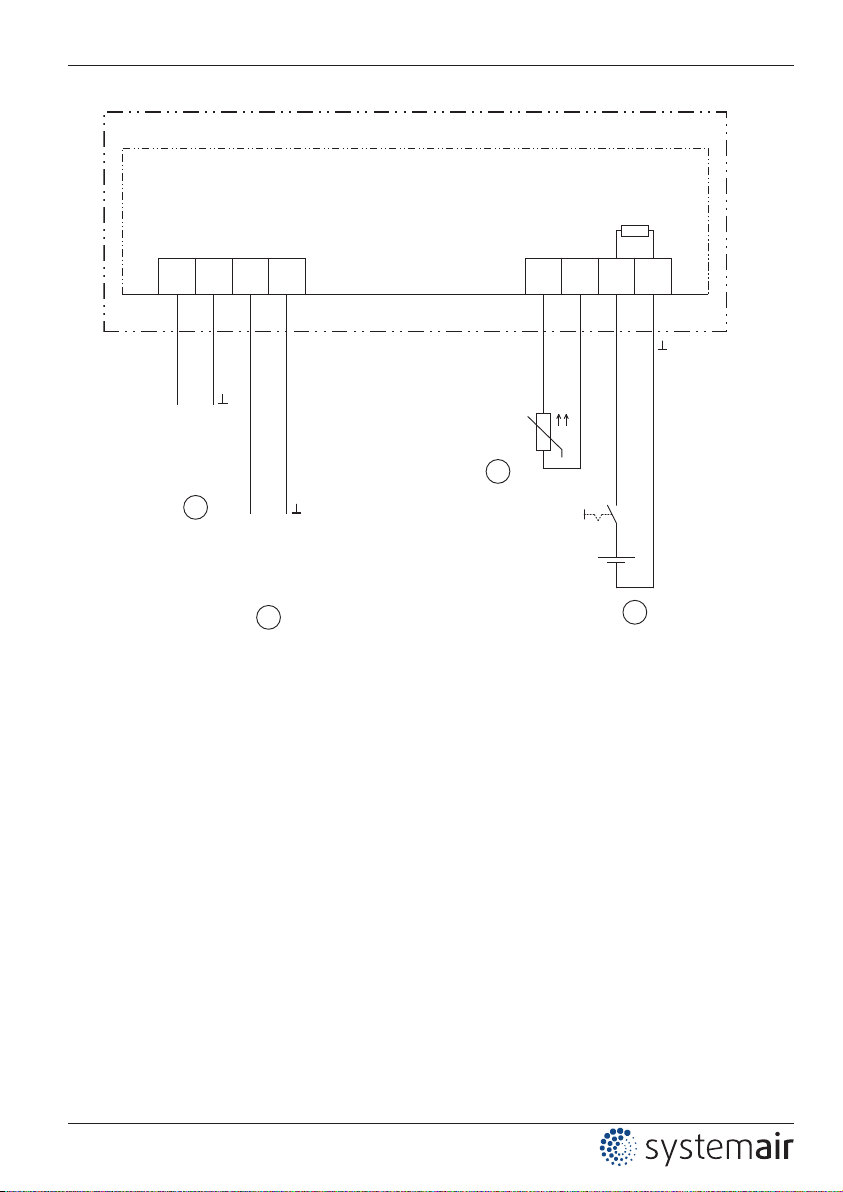
9.2 Connection diagram
GND A GND
1
2+Ub
MCTE03K1
05.10.2010
TCA 150D
Eingang
Input
10...24 V DC
(I
max
= 6 mA)
+
1
Ausgang
Output
0...10 V
(I
max
= 0.3 mA)
+
2
10...24 V DC
+
4
Ri = 4 kΩ
0 1
0 = Setpoint 1
1 = Setpoint 2
q
TF..
TF TF
KTY 81-210
PT 1000
3
+
-
1 Voltage supply 10...24 V DC
2 Output 0...10 V
3 Temperature sensor KTY 81-210 or PT 1000
4 Voltage input for switch over Setpoint 1 / Setpoint 2
Operating Instructions TCA 150D Enclosure
L-BAL-E119-GB 1318 Index 002 Part.-No. 00163357-GB
15/17
Page 16
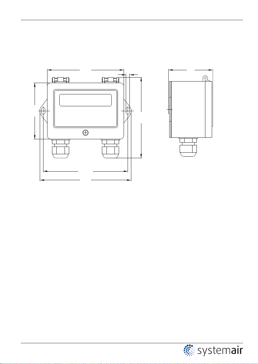
9.3 Dimensions [mm]
GM00009A
12.05.2010
104
70
95
4,5
114
108
56
Operating Instructions TCA 150D Enclosure
L-BAL-E119-GB 1318 Index 002 Part.-No. 00163357-GB
16/17
Page 17

9.4 Manufacturer reference
Our products are manufactured in accordance with the relevant international regulations.
If you have any questions concerning the use of our products or plan special uses,
please contact:
Systemair
Industrievägen 3
73930 Skinnskatteberg
Telefon:+46 (0) 222 440 00
Telefax:+46 (0) 222 440 99
mailbox@systemair.se
www.systemair.se
Operating Instructions TCA 150D Enclosure
L-BAL-E119-GB 1318 Index 002 Part.-No. 00163357-GB
17/17
 Loading...