

Page 1
Installation and maintenance manual
Manuel d’installation et de maintenance
Installations- und Wartungshandbuch
Manuale di installazione e di manutenzione
Manual de instalación y de mantenimiento
SYSCREW 380-1260
Air EVO HSE CO/TR
366
1.241 kW
FrançaisEnglish
Air Cooled Water Chillers with Screw Compressors
Refroidisseurs de liquide à condensation par air avec compresseurs à vis
Luftgekühlte Wasserkühler mit Schraubenkompressoren
Refrigeratori d’Acqua Raffreddati ad Aria con compressori a vite
Enfriadores de Agua Condensadas con Aire con compresores a tornillo
Part number / Code / Code / Codice / Código: J37276
Supersedes / Annule et remplace / Annulliert und ersezt / Annulla e sostituisce /
Anula y sustituye: Notified Body /Organisme Notifié / Benannte Zertifizierungsstelle /
Organismo Notificato / Organismo Notificado N°. 0425
ItalianoDeutsch
ISO 9001:2015 certified management system
Español
Page 2

Table of Contents
1 - FOREWORD
1.1 Introduction .......................................................................... 2
1.2 Warranty .............................................................................. 2
1.3 Emergency stop/Normal stop ...............................................2
1.4 An introduction to this manual ..............................................2
2 - SAFETY
2.1 Foreword ..............................................................................3
2.2 Definitions ............................................................................ 5
2.3 Access to the unit ...............................................................5
2.4 General precautions..............................................................5
2.5 Precautions against residual risks .........................................5
2.6 Precautions during maintenance operations ..........................6
2.7 Safety labels ................................................................. 7 & 8
2.8 Safety regulations ........................................................9 to 11
3 - TRANSPORT, LIFTING AND POSITIONING
3.1 Inspection .......................................................................... 12
3.2 Lifting ................................................................................ 12
3.3 Anchoring ..........................................................................13
3.4 Storage .............................................................................. 13
4 - INSTALLATION
4.1 Positioning of the unit .........................................................14
4.2 Spring isolator installation ................................................... 14
4.3 Place of installation ............................................................14
4.4 External water circuit ................................................. 15 & 16
4.5 Connection of water temperature sensors
(on shell and tube evaporator) ...........................................17
4.6 Hydraulic connections ....................................................... 18
4.7 Power supply .....................................................................19
4.8 Electrical connections ............................................... 19 & 20
5 - START-UP
5.1 Preliminary check ...............................................................21
5.2 Start-up ............................................................................. 21
5.3 Checking the operation ....................................................... 21
5.4 Delivery to the customer .....................................................21
6 - CONTROL
6.1 General information ............................................................ 22
6.2 Display/Keyboard ...............................................................23
6.3 Main Control Functions .............................................. 23 to 34
6.4 Setpoint .............................................................................35
6.5 Protection and Safety Equipment ........................................35
6.6 HPF version configuration ................................................... 36
7 - PRODUCT DESCRIPTION
7.1 Introduction ........................................................................ 37
7.2 General specifications ........................................................37
7.3 Compressors .....................................................................37
7.4 Refrigeration circuits ..........................................................37
7.5 Water heat exchanger .........................................................37
7.6 Air heat exchanger .............................................................. 38
7.7 Fans ...................................................................................38
7.8 Electrical power supply and control system ........................38
7.9 Accessories ....................................................................... 38
8 - TECHNICAL DATA
8.1 Pressure drops ...................................................................44
8.2 Technical data ........................................................... 45 to 48
8.3 Unit electrical data ..................................................... 49 to 51
8.4 Hydraulic Features ..................................................... 52 to 60
8.5 Position of shock adsorbers
and weight distribution on supports ....................................61
8.6 Dimensional Drawings ............................................... 62 to 73
8.7 Service spaces ...................................................................74
9 - MAINTENANCE
9.1 General requirements .........................................................75
9.2 Planned maintenance .........................................................75
9.3 Refrigerant charge ..............................................................76
9.4 Compressor ....................................................................... 76
9.5 Condenser .........................................................................76
9.6 Fans ...................................................................................77
9.7 Dehydrating filter ................................................................ 77
9.8 Sight glass ......................................................................... 77
9.9 Electronic expansion valve .................................................. 77
9.10 Evaporator .........................................................................77
10 - TROUBLESHOOTING .......................................... 78
11 - SPARE PARTS
11.1 Spare part list.....................................................................81
11.2 Oil for compressors ............................................................81
11.3 Wiring diagrams .................................................................81
12 - DISMANTLING, DEMOLITION AND SCRAPPING
12.1 Generalities ........................................................................ 82
12.2 RAEE Directive ....................................................................82
English
1
Page 3

1 - Introdução
1 - Foreword
1.1 Introduction
Units, manufactured to state-of-the-art design and implementation
standards, ensure top performance, reliability and fitness to any type
of air-conditioning systems.
These units are designed for cooling water or glycoled water (and for
water heating in models with heat recovery included) and are unfit for
any purposes other than those specified in this manual.
This manual includes all the information required for a proper
installation of the units, as well as the relevant operating and
maintenance instructions.
It is therefore recommended to read this manual carefully before
installation or any operation on the machine. The chiller installation
and maintenance must be carried out by skilled personnel only
(where possible, by one of Authorised Service Centers).
The manufacturer may not be held liable for any damage to people or
property caused by improper installation, start-up and/or improper
use of the unit and/or failure to implement the procedures and
instructions included in this manual.
1.2 Warranty
These units are delivered complete, tested and ready for being
operated. Any form of warranty will become null and void in the event
that the appliance is modified without manufacturer’s preliminary
written authorisation.
1.3 Emergency stop / Normal stop
The emergency stop of the unit can be enabled using the master
switch on the control panel (move down the lever).
For a normal stop, press the relevant push-buttons.
To restart the appliance, follow the procedure detailed in this manual.
1.4 An introduction to the manual
For safety reasons, it is imperative to follow the instructions given in
this manual. In case of any damage caused by non-compliance with
these instructions, the warranty will immediately become null and
void.
Conventions used throughout the manual:
The Danger sign recalls your attention to a
certain procedure or practice which, if not
DANGER
WARNING
followed, may result in serious damage to
people and property.
The Warning sign precedes those procedures
that, if not followed, may result in serious
damage to the appliance.
This warranty shall apply providing that the installation instructions
have been complied with (either issued by manufacturer, or deriving
from the current practice), and the Form 1 (“Start-up”) has been
filled-in and mailed to manufacturer (attn. After-Sales Service).
In order for this warranty to be valid, the following conditions shall be
met:
n The machine must be operated only by skilled personnel from
Authorised After-Sales Service.
n Maintenance must be performed only by skilled personnel - from
one of Authorised After-Sales Centers.
n Use only original spare parts.
n Carry out all the planned maintenance provided for by this manual
in a timely and proper way.
Failure to comply with any of these conditions will automatically void
the warranty.
The Notes contain important observations.
NOTE
The Useful Tips provide valuable information
that optimises the efficiency of the appliance.
USEFUL TIPS
This manual and its contents, as well as the documentation which
accompanies the unit, are and remain the property of manufacturer,
which reserves any and all rights thereon. This manual may not
be copied, in whole or in part, without manufacturer’s written
authorization.
2
Page 4
2 - Safety
2.1 Foreword
These units must be installed in conformity with the
provisions of Machinery Directive 2006/42/EC, Pressure
Equipment Directive 2014/68/EU, Electromagnetic
Compability Directive 2014/30/EU - as per EN 55011,
Group 1, Class A, as well as with other regulations
applicable in the country of installation. If these provisions
are not complied with, the unit must not be operated.
Compressors with frequency inverter (FI) are installed. Several
electrical connections are required and all are established inside the
terminal box. FI and the compressor motor are Permanently wired
and the compressor motor cannot be operated without FI. As soon as
the FI is under voltage, the capacitors in the FI intermediate circuit are
charged and from this moment on, all the electrical components in
the terminal box present risks.
Hazardous voltages in frequency inverter
housing! Any contact will cause severe injury
or death. Never open FI housing during
operation. In case of any operation in the
FI housing, switch off the main switch and
DANGER
secure it against being switched on again.
Wait for at least 5 minutes until all capacitors
have been discharged. Close perfectly the FI
housing before switching on again
The unit must be grounded and no installation
and/or maintenance operations may be
carried out before deenergising the electrical
panel of the unit and protect against restoring
DANGER
power. Wait at least 5 minutes for capacitors
to de-energize!
Failure to respect the safety measures mentioned above may result
in electrocution hazard and fire in the presence of any short-circuits.
Inside the heat exchangers, the compressors
and the refrigeration lines, this unit contains
liquid and gaseous refrigerant under
DANGER
pressure. The release of this refrigerant may
be dangerous and cause injuries.
The units are not designed to be operated with
natural refrigerants, such as hydrocarbons.
Manufacturer may not be held liable for any
problems deriving from the replacement
DANGER
of original refrigerant or the introduction of
hydrocarbons.
Units are designed and manufactured according to the requirements
of European Standard PED 2014/68/EU (pressure vessels directive).
English
The inverter compressor is provided with the safety fuction called
"Safe Torque Off" (STO), that is used as device for removal power
for prevention of unexpected start-up. As long as this function is
activated, no drive energy is transferred to the compressor motor,
so the compressor motor is safely free of torque, but it is not
de-energized. That means that, even if the compressor has been
stopped by the "Safe Torque Off" (STO) or "motoroff" function, the FI
remains energized.
Even in the cases described above the main
switch must be switched off and must be
waited for at least 5 minutes before any
DANGER
operation in th FI housing
Due to the use of compressor frequency inverter,
the unit may produce a strong magnetic field
Keep magnetic and magnetizable objetcs away
from the unit. Persons with cardiac pacemakers,
WARNING
implanted heart defibrillators or metallic implants
must maintain a clearance of at least 30cm from
the compressor.
n The used refrigerants are included in group II (non-hazardous
fluids).
n The maximum working pressure values are mentioned on the
unit’s data plate.
n Suitable safety devices (pressure switches and safety valves)
have been provided, to prevent any anomalous overpressure
inside the plant.
n The vents of the safety valves are positioned and oriented in such
a way as to reduce the risk of contact with the operator, in the
event that the valve is operated. Anyway, the installer will convey
the discharge of the valves far from the unit.
n Dedicated guards (removable panels with tools) and danger signs
indicate the presence of hot pipes or components (high surface
temperature).
3
Page 5
2 - Safety (continued)
DANGER
DANGER
DANGER
The guards of the fans (only for units provided
with air heat exchangers) must be always
mounted and must never be removed before
de-energising the appliance.
The standard unit is provided with fans
protection grill always factory mounted.
For specific customer requests, mainly due
to limiting transport conditions, it is still
possible the unit is shipped with fans not
fully assembled. In this circumstance, before
switching on the unit, it is mandatory that
the Customer/Installer completes the fans
assembling on field - including fan protection
grills -according to the instructions included
into the manual.
It is the User’s responsibility to ensure that
the unit is fit for the conditions of intended use
and that both installation and maintenance are
carried out by experienced personnel, capable
of respecting all the recommendations
provided by this manual.
It is important that the unit is adequately
supported, as detailed in this manual. Noncompliance with these recommendations may
create hazardous situations for the personnel.
WARNING
WARNING
The unit has not been design to withstand
loads and/or stress that may be transmitted by
adjacent units, piping and/or structures.
Each external load or stress transmitted to the
unit may break or cause breakdowns in the
unit’s structure, as well as serious dangers to
people. In these cases, any form of warranty will
automatically become null and void.
The packaging material must not be disposed of
in the surrounding environment or burnt.
DANGER
The unit must rest on a base which meets the
characteristics specified in this manual; a
base with inadequate characteristics is likely
to become a source of serious injury to the
personnel.
4
Page 6

2 - Safety (continued)
2.2 Definitions
OWNER: means the legal representative of the company, body or
individual who owns the plant where unit has been installed; he/she
has the responsibility of making sure that all the safety regulations
specified in this manual are complied with, along with the national
laws in force.
INSTALLER: means the legal representative of the company who has
been given by the owner the job of positioning and performing the
hydraulic, electric and other connections of unit to the plant: he/she
is responsible for handling and properly installing the appliance, as
specified in this manual and according to the national regulations in
force.
OPERATOR: means a person authorised by the owner to do on unit
all the regulation and control operations expressly described in this
manual, that must be strictly complied with, without exceeding the
scope of the tasks entrusted to him.
ENGINEER: means a person authorised directly by manufacturer or,
in all EC countries, excluding Italy, under his full responsibility, by
the distributor of product, to perform any routine and extraordinary
maintenance operations, as well as any regulation, control, servicing
operations and the replacement of pieces, as may be necessary
during the life of the unit.
2.3 Access to the unit
disassemble connections, filters, joints or other line items
n do not use your hands to check for any pressure drops
n use tools in a good state of repair; be sure to have understood the
instructions before using them
n be sure to have removed all tools, electrical cables and any other
objects before closing and starting the unit again
2.5 Precautions against residual risks
Prevention of residual risks caused by the control
system
n be sure to have perfectly understood the operating instructions
before carrying out any operation on the control panel
n when you have to work on the control panel, keep always the
operating instructions within reach
n start the unit only after you have checked its perfect connection to
the plant
n promptly inform the ENGINEER about any alarm involving the unit
n do not reset manual restoration alarms unless you have identified
and removed their cause
English
The unit must be placed in an area which can be accessed also
by OPERATORS and ENGINEERS; otherwise the unit must be
surrounded by a fence at not less than 2 meters from the external
surface of the machine.
OPERATORS and ENGINEERS must enter the fenced area only
after wearing suitable clothing (safety shoes, gloves, helmet etc.).
The INSTALLER personnel or any other visitor must always be
accompanied by an OPERATOR.
For no reason shall any unauthorised personnel be left alone in
contact with the unit.
2.4 General precautions
The OPERATOR must simply use the controls of the unit; he must not
open any panel, other than the one providing access to the control
module.
The INSTALLER must simply work on the connections between plant
and machine; he must not open any panels of the machine and he
must not enable any control.
When you approach or work on the unit, follow the precautions listed
below:
n do not wear loose clothing or jewellery or any other accessory tat
may be caught in moving parts
n wear suitable personal protective equipment (gloves, goggles
etc.) when you have to work in the presence of free flames
(welding operations) or with compressed air
Prevention of residual mechanical risks
n install the unit according to the instructions provided in this
manual
n carry out all the periodical maintenance operations prescribed by
this manual
n wear a protective helmet before accessing the interior of the unit
n before opening any panelling of the machine, make sure that it is
secured to it by hinges
n do not touch air condensation coils without wearing protective
gloves
n do not remove the guards from moving elements while the unit is
running
n check the correct position of the moving elements’ guards before
restarting the unit
Prevention of residual electrical risks
n connect the unit to the mains according to the instructions
provided in this manual
n periodically carry out all the maintenance operations specified by
this manual
n disconnect the unit from the mains by the external disconnecting
switch before opening the electrical board
n if the unit is placed in a closed room, wear ear protection devices
n cut off connecting pipes, drain them in order to balance the
pressure to the atmospheric value before disconnecting them,
n check the proper grounding of the unit before start-up
n check all the electrical connections, the connecting cables, and in
particular the insulation; replace worn or damaged cables
5
Page 7

2 - Safety (continued)
n periodically check the board’s internal wiring
n do not use cables having an inadequate section or flying
connections, even for limited periods of time or in an emergency
Prevention of other residual risks
n make sure that the connections to the unit conform to the
instructions provided in this manual and on the unit’s panelling
n if you have to disassemble a piece, make sure that it has been
properly mounted again before restarting the unit
n do not touch the delivery pipes from the compressor, the
compressor and any other piping or component inside the
machine before wearing protective gloves
n keep a fire extinguisher fir for electrical appliances near the
machine
n on the units installed indoor, connect the safety valve of the
refrigeration circuit to a piping network that can channel any
overflowing refrigerant outside
n remove and leak of fluid inside and outside the unit
n collect the waste liquids and dry any oil spillage
n periodically clean the compressor compartment, to remove any
fouling
n place a warning sign “do not turn on - maintenance in progress”
on the external disconnecting switch
n make sure that on-off remote controls are inhibited
n wear suitable personal protective equipment (helmet, safety
gloves, goggles and shoes etc.)
To carry out any measurements or checks which require the
activation of the machine:
n work with the electrical board open only for the necessary time
n close the electrical board as soon as the measurement or check
has been completed
n for outdoor units, do not carry out any operations in the presence
of dangerous climatic conditions (rain, snow, mist etc.)
The following precautions must be always adopted:
n do not scatter the fluids of the refrigeration circuit in the
surrounding environment
n when replacing an eprom or electronic cards, use always suitable
devices (extractor, antistatic bracelet, etc.)
n to replace a compressor, the evaporator, the condensing coils or
any other weighty element, make sure that the lifting equipment is
consistent with the weight to be lifted
n do not store flammable liquids near the unit
n do not disperse the refrigerant and the lubricating oil into the
environment
n weld only empty pipes; do not approach flames or other sources
of heat to refrigerant pipes
n do not bend/hit pipes containing fluids under pressure
2.6 Precautions during maintenance operations
Maintenance operations can be carried out by authorised technicians
only.
Before performing any maintenance operations:
n disconnect the unit from the mains with the external disconnecting
switch
n in air units with independent compressor compartment, do not
access the fan compartment unless you have disconnected the
machine by the disconnecting switch on the board and you have
placed a warning sign “do not turn on - maintenance in progress”
n contact manufacturer for any modifications to the refrigeration,
hydraulic or wiring diagram of the unit, as well as to its control
logics
n contact manufacturer if it is necessary to perform very difficult
disassembly and assembly operations
n use only original spare parts purchased directly from manufacturer
or the official retailers of the companies on the recommended
spare parts list
n contact manufacturer if it is necessary to handle the unit one year
after its positioning on site or if you wish to dismantle it.
6
Page 8
2 - Safety (continued)
corrente antes
ATTENTION! Don’t leave the unit with water inside hydraulic circuit during
winter or when it is in stand by.
ATTENZIONE! Non lasciare l’unità con acqua nel circuito idraulico durante
l’inverno o quando non è funzionante.
ATTENTION! Ne laissez pas l’unitè avec de l’eau dans le circuit hydraulique
pendant l’hiver ou quand elle ne travaille pas.
WARNUNG! Lassen Sie nicht das Wasser in die Schaltung während des
Winters oder wenn es nicht funktionient.
¡ATENCÍON! No deje el agua en el circuito hidráulico durante el invierno o
cuando no esta trabajando.
PRODUCT CODE
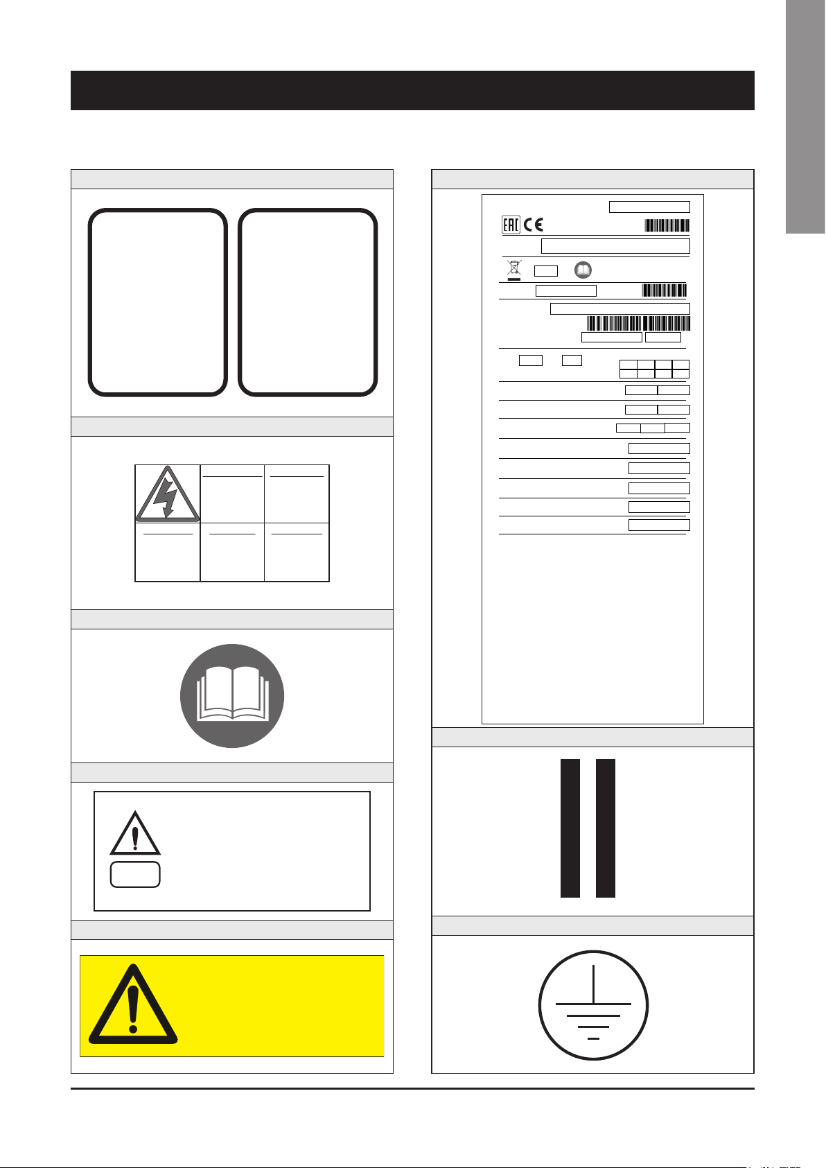
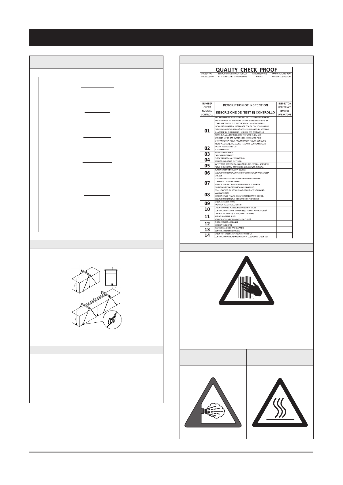
2.7 Safety labels
Identification of the refrigerant - External door
USARE SOLO
R134a
E
SPECIAL ESTER OIL
RECUPERARE FLUIDO - NON DISPERDERE NELL’AMBIENTE - REGOLAMENTO CEE N° 3093/94
USE ONLY
Electrical warning - Adjacent to the master switch
ATTENZIONE !
aprire togliere
ACHTUNG !
Vor offnen des
gehauses
hauptschalter
ausschalten
Read the instruction on the electrical board
CAUTION !
Disconnect
supply before
USARE SOLO
R513A
SPECIAL ESTER OIL
RECOVER - DO NOT VENT - EEC REGULATION N° 3093/94
RECUPERARE FLUIDO - NON DISPERDERE NELL’AMBIENTE - REGOLAMENTO CEE N° 3093/94
Prima di
tensione
electrical
opening
E
USE ONLY
ATTENTION !
Enlever
l’alimentation
electrique
avant d’ouvrir
ATENCION !
Cortar la
de abrir
el aparato
RECOVER - DO NOT VENT - EEC REGULATION N° 3093/94
Identification of the unit - Outside, on the right-hand front column
CODICE PRODOTTO NEUTRO
PRODUCT CODE
MODELLO
MODEL
0425
MO.NO
MATRICOLA
SERIAL NO.
ANNO DI COSTRUZIONE
Manuf. Year
REFR.
PS (LATO ALTA / LATO BASSA)
PS (HIGH / LOW SIDE)
TS (ALTA / BASSA)
TS (HIGH / LOW)
ALIM. POTENZA
MAIN SUPPLY
CORRENTE DI SPUNTO
LRA
CORRENTE A PIENO CARICO
FLA
POTENZA ASSORBITA
POWER INPUT
PRESS. MAX ESERCIZIO ACQUA
MAX WATER OPERATING PRESSURE
MASSA
MASS
SYSTEMAIR S.r.l. Via XXV Aprile 29 20825 BARLASSINA MB ITALIA
MADE IN ITALY COD.NO: P35952
MODELLO:
MODEL
MATRICOLA:
SERIAL NO.
CODICE:
PRODUCT CODE
MODELLO:
MODEL
MATRICOLA:
SERIAL NO.
CODICE:
PRODUCT CODE
MODELLO:
MODEL
MATRICOLA:
SERIAL NO.
CODICE:
GWP
CIRCUIT 1 2 3 4
CHARGE (Kg)
(tCO₂eq)
bar
°C
V / PH / Hz
(max) A
(max) A
(max) Kw
bar
Kg
ANNO DI COSTRUZIONE
Manuf. Year
ANNO DI COSTRUZIONE
Manuf. Year
ANNO DI COSTRUZIONE
Manuf. Year
Gravity centre - Base
English
On the compressor box
BEFORE OPENING THE PANEL, THE
UNIT MUST STAY SWITCHED OFF
FOR AT LEAST 5 MINUTES
WARNING
PRIMA DI APRIRE IL PANNELLO
L'UNITÀ DEVE RESTARE SPENTA PER
ALMENO 5 MINUTI
Circuit drain - Outside, on the right-hand front column
ON THIS LINE
KEEP LIFT HOOK
TENERE SU QUESTA LINEA
GANCIO DI SOLLEVAMENTO
Grounding connection on the electrical board, adjacent to the connection
7
Page 9
2 - Safety (continued)
ATENCION! PERFIL AFILADO
Start-up warning - Outside the door
of the electrical board
INSERIRE LE RESISTENZE DI RISCALDAMENTO OLIO ALMENO 12
ORE PRIMA DI OGNI AVVIAMENTO (SE PREVISTE)
PRIMA DELLA MESSA IN TENSIONE ASSICURARSI CHE LE VITI DEI
CIRCUITI ELETTRICI SIANO SERRATE COMPLETAMENTE
ENERGIZE THE CRANCKCASE HEATER FOR AT LEAST 12 HOURS
BEFORE EACH STARTING (IF FITTED)
BEFORE TIGHTENING-UP, TO TIGHTEN ALL TERMINAL SCREWS
ESPECIALLY THOSE IN MAIN CIRCUIT
OLSUMPFHEIZUNG (FALLS VORHANDEN) 12 STUNDEN VOR DEM
START EINSCHALTEN
VOR INBETRIEBNAHME ALLE SCHRAUBENVERBINDUNGEN
NACHZIEHEN, BESONDERS DIE ELEKTRISCHEN ANSCHLUSSE
ALIMENTER ELECTRIQUEMENT LA RESISTANCE DE CARTER AU
MOINS 12 HEURES AVANT CHAQUE DEMARRAGE (SI MONTE SUR
LE PRODUIT)
AVANT DE DEMARRER LA MACHINE, VERIFIER LE SERRAGE DE
TOUTES LES BORNES A VIS, SPECIALEMENT DANS LE BOITIER
ELECTRIQUE
ATENCIÓN ALIMENTAR ELÉCTRICAMENTE LA RESISTENCIA DE
CARTER AL MENOS 12 HORAS ANTES DE CADA PUESTA EN
MARCHA (SI ESTA EQUIPADA EN LA UNIDAD)
ANTES DE LA PUESTA EN MARCHA, COMPROBAR QUE LOS
BORNES ESTAN BIEN APRETADOS, ESPECIALMENTE EN EL
CUADRO ELÉCTRICO
035B00057-000 MADE IN ITALY
ATTENZIONE
WARNING
WARNUNG
ATTENTION
ATENTION
Final Test Certificate - Inside the external door
Instruction for the lifting
Fitting identification - Adjacent to fittings
EIN - INLET
ENTRÉE - ENTRATA
AUS - OUTLET
SORTIE - USCITA
On the coil
ATTENZIONE! BORDI TAGLIENTI
VORSICHT! SCHARFE RÄNDER
CAUTION! SHARP EDGES
ATTENTION! BORDS COUPANTS
Warning - Safety valve vents
Warning - High temperature
zone adjacent to hot pipes or
components
8
Page 10

2 - Safety (continued)
2.8 Safety regulations
REFRIGERANT DATA SAFETY DATA: R134a/R513A
ASHRAE Number: R134a
R134a
R513A
Toxicity Low
Contact with skin
Contact with eyes
Composition: R134a
ASHRAE Safety classification: A1
ASHRAE Number: R513A
Composition: HFO-1234yf /R134a
ASHRAE Safety classification: A1
If sprayed, the refrigerant is likely to cause frost burns. If absorbed by the skin, the danger is very limited;
it may cause a slight irritation, and the liquid is degreasing. Unfreeze the affected skin with water.
Remove the contaminated clothes with great care - in the presence of frost burns, the clothes may stick
to the skin. Wash with plenty of warm water the affected skin.
In the presence of symptoms such as irritation or blisters, obtain medical attention.
Vapours do not cause harmful effects. The spraying of refrigerant may cause frost burns.
Wash immediately with a proper solution or with tap water for at least 15 minutes, and then obtain
medical attention.
English
Very unlikely - should something happen, it will cause frost burns.
Ingestion
Inhalation
Recommendations
Prolonged exposure
Professional levels Recommended threshold: 1000 ppm v/v - 8 hours TWA.
Do not induce vomiting. Only if the patient is conscious, wash out mouth with water and give some
250 ml of water to drink. Then, obtain medical attention.
Remarkable concentrations in the air may have an anaesthetic effect, up to fainting.
The exposure to considerable amounts may cause irregular heartbeat, up to the sudden death of the
patient. Very high concentrations may result in the risk of asphyxia, due to the reduction in the oxygen
percentage in the atmosphere. Remove the patient to fresh air and keep warm and at rest.
If necessary, give oxygen. In case of breathing difficulties or arrest, proceed with artificial respiration.
In case of cardiac arrest, proceed with cardiac massage. Then, obtain medical attention.
Semiotics or support therapy is recommended. Cardiac sensitisation has been observed that, in
the presence of circulating catecholamines such as adrenalin, may cause cardiac arrhythmia and
accordingly, in case of exposure to high concentrations, cardiac arrest.
A study on the effects of exposure to 50,000 ppm during the whole life of rats has identified the
development of benign testicle tumour.
This situation should therefore be negligible for personnel exposed to concentrations equal to or lower
than professional levels.
Stability Not specified
Conditions to avoid Do not use in the presence of flames, burning surfaces and excess humidity.
9
Page 11
2 - Safety (continued)
2.8 Safety regulations (continued)
REFRIGERANT DATA SAFETY DATA: R134a/R513A
Hazardous reactions
Hazardous decomposition
products
General precautions
Respiratory system protection
Storage
Protective clothing
Accidental release measures
May react with sodium, potassium, barium and other alkaline metals.
Incompatible substances: magnesium and alloys with magnesium concentrations > 2%.
Halogen acids produced by thermal decomposition and hydrolysis.
Do not inhale concentrated vapours. Their concentration in the atmosphere should not exceed the
minimum preset values and should be maintained below the professional threshold. Being more weighty
than the air, the vapour concentrates on the bottom, in narrow areas. Therefore, the exhaust system must
work at low level.
If you are in doubt about the concentration in the atmosphere, it is recommended to wear a respirator
approved by an accident-prevention
Authority, of the independent or oxygen type.
Cylinders must be stored in a dry and fresh place, free from any fire hazard, far from direct sunlight or
other sources of heat, radiators etc.
Keep a temperature below 50 °C.
Wear overalls, protective gloves and goggles or a mask.
It is important to wear protective clothing and a respirator.
Stop the source of the leak, if you can do this without danger. Negligible leaks can be left evaporating
under the sun, providing that the room is well ventilated.
Considerable leaks: ventilate the room. Reduce the leak with sand, earth or other absorbing substances.
Make sure that the liquid does is not channelled into gutters, sewers or pits where the vapours are likely
to create a stuffy atmosphere.
Disposal
Fire fighting information Not flammable in the atmosphere.
Cylinders The cylinders, if exposed to fire, shall be cooled by water jets; otherwise, if heated, they may explode.
Protective fire fighting equipment In case of fire, wear an independent respirator and protective clothing.
The best method is recovery and recycling. If this method is not practicable, dispose according to an
approved procedure, that shall ensure the absorption and neutralization of acids and toxic agents.
10
Page 12
2 - Safety (continued)
2.8 Safety regulations (continued)
LUBRICANT OIL DATA SAFETY DATA: ESTER OIL
Classification Not harmful.
May cause slight irritation. Does not require first aid measures. It is recommended to follow usual
Contact with skin
Contact with eyes Wash thoroughly with a suitable solution or tap water.
Ingestion Seek medical advice immediately.
Inhalation Seek medical advice immediately.
Conditions to avoid
Protection of the
respiratory system
personal hygiene measures, including washing the exposed skin with soap and water several times a day.
It is also recommended to wash your overalls at least once a week.
Strong oxidising substances, caustic or acid solutions, excess heat.
May corrode some types of paint or rubber.
Use in well ventilated rooms.
English
Protective clothing
Accidental release measures
Disposal
Fire fighting information
Cylinders The cylinders exposed to a fire will be cooled with water jets in case of fire.
Fire fighting protective equipment In case of fire, wear an independent respirator.
Always wear protective goggles or a mask. Wearing protective gloves is not mandatory, but is
recommended in case of prolonged exposure to refrigerant oil.
It is important to wear protective clothing and, especially, goggles.
Stop the source of the leak. Reduce the leak with absorbing substances (sand, sawdust or any other
absorbing material available on the market).
The refrigerant oil and its waste will be disposed of in an approved incinerator, in conformity with the
provisions and the local regulations applicable to oil waste.
In the presence of hot liquid or flames, use dry powder, carbon dioxide or foam. If the leak is not burning,
use a water jet to remove any vapours and to protect the personnel responsible for stopping the leak.
11
Page 13
3 - Transport, Lifting and Positioning
Refrigerators are supplied assembled (apart from standard
antivibrating rubber supports, that will be installed on site). The
equipment are full of refrigerant and oil, in the quantity required for a
proper operation.
3.1 Inspection
When the unit is delivered, it is recommended to check it carefully
and to identify any damage occurred during transportation. The
goods are shipped ex-factory, at the buyer’s risk. Check that the
delivery includes all the components listed in the order.
In case of damage, note it down on the carrier’s delivery note and
issue a claim according to the instructions provided in the delivery
note.
In the presence of any serious damage, that does not affect the
surface only, it is recommended to inform manufacturer immediately.
Please note that manufacturer may not be held liable for any damage
to the equipment during transportation, even though the carrier has
been appointed by the factory.
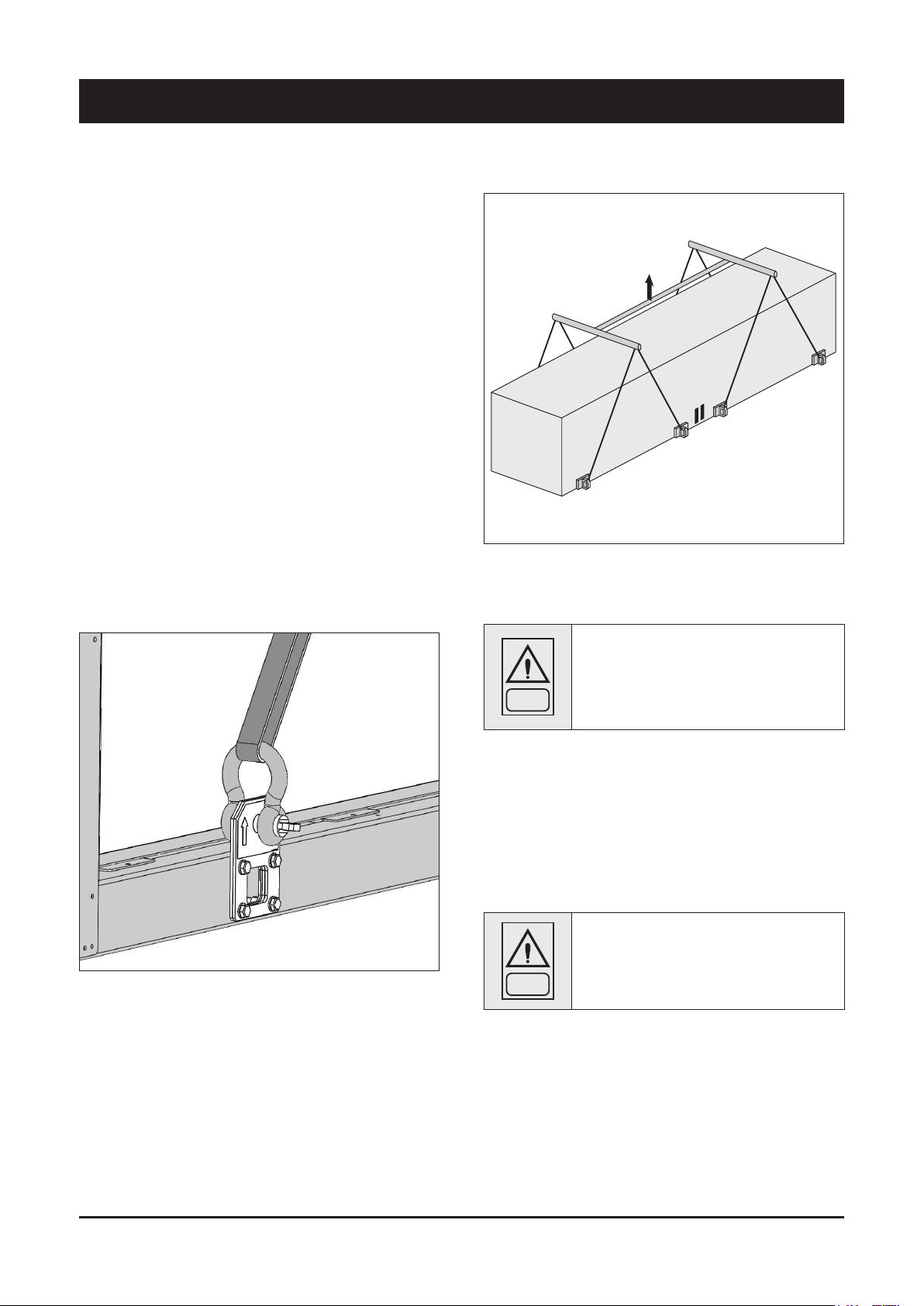
3.2 Lifting
The unit must be lifted by using the hooks inserted into the relevant
eyebolts (see the figure).
It is recommended to use a spacer to prevent cables from
damaging the unit (see the figure).
Before positioning the unit, make sure that the place of installation is
appropriate and sturdy enough to hold the weight and to withstand
the stress caused by the operation of the whole assembly.
Do not displace the unit on rollers, and do not
lift it with a lift truck.
Unit must be lifted carefully.
WARNING
To lift unit slowly and regularly.
To lift and displace the unit:
n
Insert and secure eyebolts into the holes marked on the frame.
n
Insert spacer between cables.
n
Hook near the barycentre of the unit.
n
The cables must be long enough to form, if tensioned, an angle
of at least 45° with respect to the horizontal plane.
For lifting operations, use only tools and
material fit for this purpose, in accordance with
WARNING
accident-prevention regulations.
12
Page 14
WARNING
3 - Transport, Lifting and Positioning (continued)
During the lifting and handling of the unit, be
careful not to damage the finned pack of the
coils positioned on the sides of the unit.
The sides of the unit must be protected by
cardboard or plywood sheets.
English
The eyebolts must be mounted on the unit whenever it shall be
displaced and then lifted again.
3.3 Anchoring
It is not essential to secure the unit to the foundations, unless in
areas where there is a serious risk of earthquake, or if the appliance
is installed on the top of a steel frame.
WARNING
WARNING
It is recommended not to remove the protective
plastic envelope, that should prevent scraps
from penetrating into the appliance and any
damage to the surfaces, until the unit is ready
for operation.
The lifting eyebolts protrude from the base
of the unit; it is therefore recommended to
remove them once the unit has been lifted and
positioned, if in your opinion they are likely to
become a source of hazard and injury.
3.4 Storage
When the unit is to be stored before installation, adopt a few
precautions to prevent any damage or risk of corrosion or wear:
n plug or seal every single opening, such as water fittings
n do not store the appliance in a room where the temperature
exceeds 50 °C and, if possible, do not expose to direct sunlight
n minimum storage temperature is -20 °C
n it is recommended to store the unit in a roof where traffic is
minimized, to prevent the risk of accidental damage
n the unit must not be washed with a steam jet
n take away and leave to the site manager all the keys providing
access to the control board
Finally, it is recommended to carry out visual inspections at regular
intervals.
13
Page 15
4 - Installation
4.1 Positioning of the unit
Before installing the unit, make sure that the
structure of the building and/or the supporting
surface can withstand the weight of the
DANGER
These units have been designed for outdoor installation on a solid
surface. Standard accessories include antivibrating rubber supports,
that must be positioned under the base.
When the unit is to be installed on the ground, it is necessary to
provide a concrete base, to ensure a uniform distribution of the
weights.
As a general rule, no special sub-bases are required. However, if the
unit is to be installed on the top of inhabited rooms, it is advisable
to rest it on spring shock absorbers (optional), that will minimise the
transmission of any vibration to the structures.
To choose the place of installation of the unit, bear in mind that:
n the longitudinal axis of the unit must be parallel to the direction of
prevailing winds, so as to ensure a uniform distribution of the air
on finned exchangers
appliance. The weights of the units are listed in
Chapter 8 of this manual.
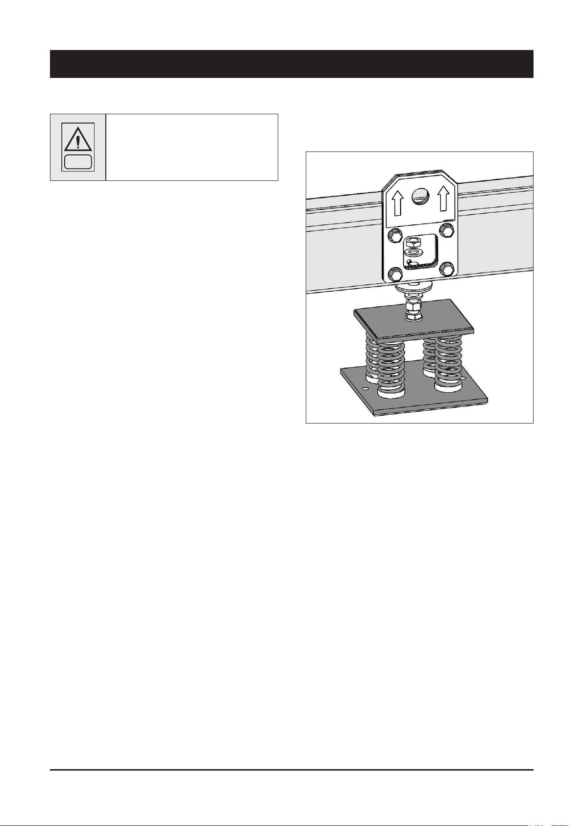
4.2 Spring Isolator Installation
n
Prepare the base, that must be flat and plane.
n
Lift the appliance and inser t shock absorbers as follows:
n the unit must not be installed near boilers’ vent pipes
n the unit must not be installed leeward with respect to sources of
air contaminated by greases, such as, for example, the outlets
to kitchen exhaust hoods into the atmosphere. Otherwise,
the grease is likely to deposit on the fins of the refrigerant /air
exchangers, and would fix every type of atmospheric impurity,
resulting in the quick clogging of the exchangers
n the unit must not be installed in areas subject to considerable
snow falling
n the unit must not be installed in areas subject to flooding, under
gutters etc.
n the unit must not be installed in air shafts, narrow courts or other
small places, where the noise may be reflected by the walls or
the air ejected by fans may short-circuit itself on refrigerant/air
heat exchangers or condenser
n the place of installation must be have all the necessary spaces
for air circulation and maintenance operations (see Chapter 8).
4.3 Place of installation
In the place of installation the air temperature average during 24
hours must be lower than 40°C.
The place of installation's altitude must be lower than 2000 m.
14
Page 16
4 - Installation (continued)
4.4 External Water Circuit
The flow switch and the filter water, although not included in the
supply, must always be fitted such as plant components.
Their installation is mandatory for warranty.
The external hydraulic circuit must ensure the
water flow to the evaporator under any working
WARNING
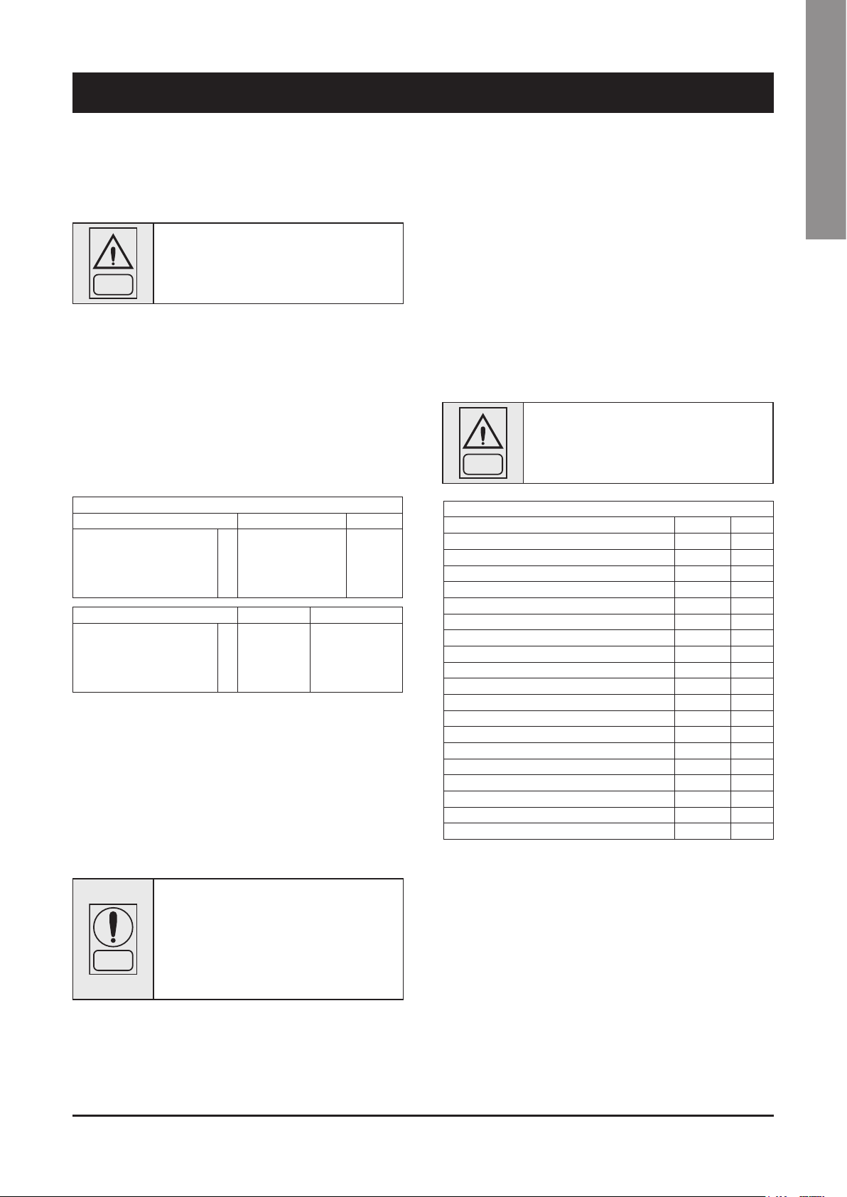
The circuit shall be composed by the following elements:
n
A circulation pump which can ensure the necessary capacity
and discharge head.
n
The capacity of the primary hydraulic circuit should not be less
than the minimum water volumes shown in the table below, in
order to prevent the repeated start-up of the compressor and any
damage to it. If the water capacity in the primary piping of the
circuit and in the evaporator is lower than this value, an insulated
storage tank shall be installed.
SYSCREW AIR EVO HSE 380-450-510-590-660 730-810
Recommended system chilled
water volume
SYSCREW AIR EVO HSE 900-980 1060-1160-1260
Recommended system chilled
water volume
4
Minimum water contents at normal air conditioning applications
The following formula must be respected
Vmin = Cap * MinCapStep * 28,8 , where
Cap = Nominal Unit Capacity [kW] at conditions of installation
MinCapStep = Minimum unit capacity step [%] shown in Technical Data
Table
If the application is a process cooling type, the minimum system chilled water
volume is generally higher than above recommended.
In this case, please contact your nearest Systemair Sales Office
n
A membrane expansion vessel provided with safety valve with
vent, that must be visible.
NOTE
or adjustment conditions.
MINIMUM WATER VOLUMES
4
4
l 2334 2953
l 3608 5017
The capacity of the expansion vessel must allow
for an expansion of at least 2% of the volume of
the fluid in the circuit (evaporator, piping, user
circuit and standby tank, if any). The expansion
vessel needs not be isolated, because no water
can circulate inside it.
As a general rule, the flow switch shall be mounted on a horizontal
pipe, at a distance from the curves equal to 10 times the diameter
of the pipe and far from valves or other components that are likely
to hinder the water flow upstream of or downstream from the flow
switch.
n
The bleed valves must be mounted on the highest point of the pip-
ing.
n
The stop valves must be mounted on the piping of the water en-
tering/leaving the evaporator.
n
The drain points (provided with plugs, cocks etc.) must be ar-
ranged in the lowest point of the piping.
The flow switch must be connected (terminals
1-2) as shown in the wiring diagram of the
WARNING
PH 7,5 - 9
Electrical conductivity 10 - 500 μS/cm
Total hardness 4,5 - 8,5 dH
Temperature < 60 [°C]
Alkalinity (HCO
Alkalinity / Sulphates (HCO
Sulphates (SO
Chlorides (Cl-) < 50 ppm
Free Chlorine < 0,5 ppm
Phosphates (PO
Ammonia (NH3) < 0,5 ppm
Ammonium Ion (NH
Manganese Ion (Mn2+) < 0,05 ppm
Free Carbon Dioxide (CO2) < 5 ppm
Hydrogen Sufide (H2S) < 0,05 ppm
Oxygen Content < 0,1 ppm
Nitrates (NO
Manganese (Mn) < 0,1 ppm
Iron (Fe) < 0,2 ppm
Aluminium (Al) < 0,2 ppm
Caution
If the water circuit is to be drained for a time exceeding one month, the
circuit must be fully charged with nitrogen to prevent any risk of corrosion
by differential venting
“User’s Terminal Box”.
RECOMMENDED WATER COMPOSITION
-
) 70-300 ppm
3
2-
) < 70 ppm
4
3-
4
-
) < 100 ppm
3
-
2-
/ SO
) > 1 ppm
3
4
) < 2 ppm
+
) < 2 ppm
4
English
A flow switch will stop the unit when the water is not circulating or a
flow rate problem occurs.
To install the flow switch, follow the manufacturer’s instructions.
15
Page 17
4 - Installation (continued)
Then:
n
Provide the evaporator with a by-pass circuit equipped with a
valve to wash the plant.
n
Insulate the piping, to prevent the risk of heat loss.
n
Position a filter on the suction side of the evaporator of the heat
recovery condenser.
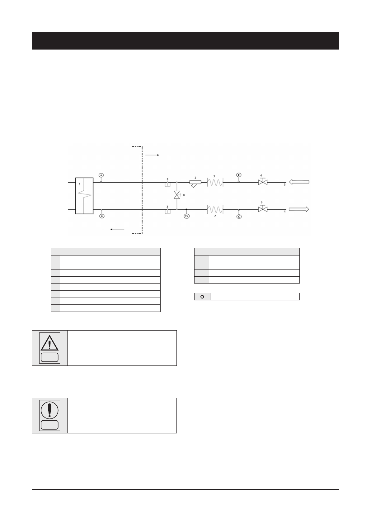
Standard hydraulic circuit
User side
Unit side
INLET
OUTLET
COMPONENTS
1 Shell & Tube Heat Exchanger
2 Water Filter
3 Pressure point/drain
4 Water outlet
5 Water inlet
6 Globe valve
7 Flexible pipe
8 By-pass valve
Before filling the circuit, it is important to check
that it is free from any foreign matter, sand,
gravels, rust, welding deposits, waste and other
WARNING
materials that may damage the evaporator.
When cleaning the lines, it is recommended to create a circuit bypass. It is important to mount a filtering medium (30 mesh) upstream
of the chiller.
If necessary, the water required to fill the circuit
must be treated to obtain the requested pH.
NOTE
SAFETY/CONTROL DEVICES
A Inlet water temp. sensor
B Outlet water temp. sensor
C Thermometer
FS Flow switch
Probes
16
Page 18
4 - Installation (continued)
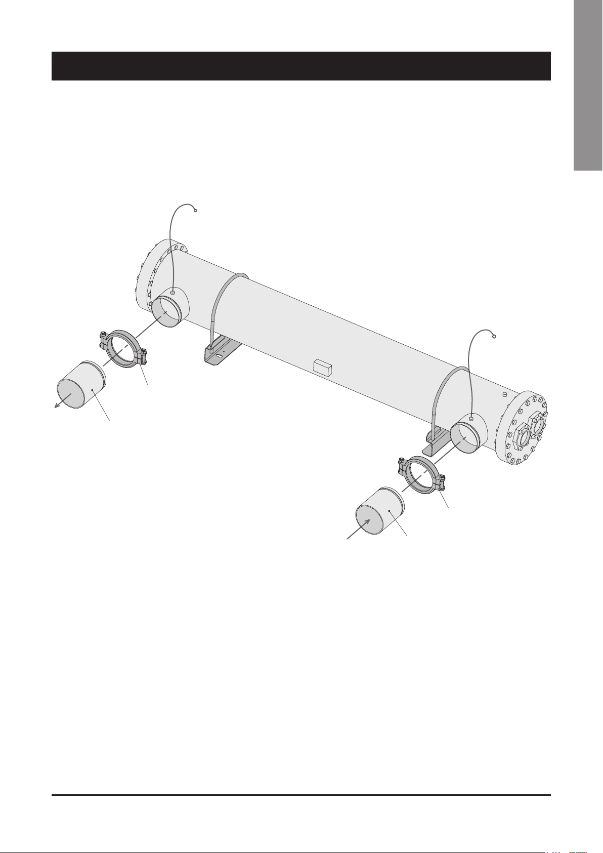
4.5 Water connections for base unit
configuration (without hydraulic options)
The units are provided with fittings for hydraulic connections between
heat exchangers and plant.
BT OUT
English
Each fitting is complete with sensor well to fasten temperature
sensor (BT-IN and BT-OUT). Fittings are supplied separate and must
be mounted during the installation of the unit.
BT IN
OUT
VICTAULIC JOINT
FITTING
VICTAULIC JOINT
IN
FITTING
17
Page 19
4 - Installation (continued)
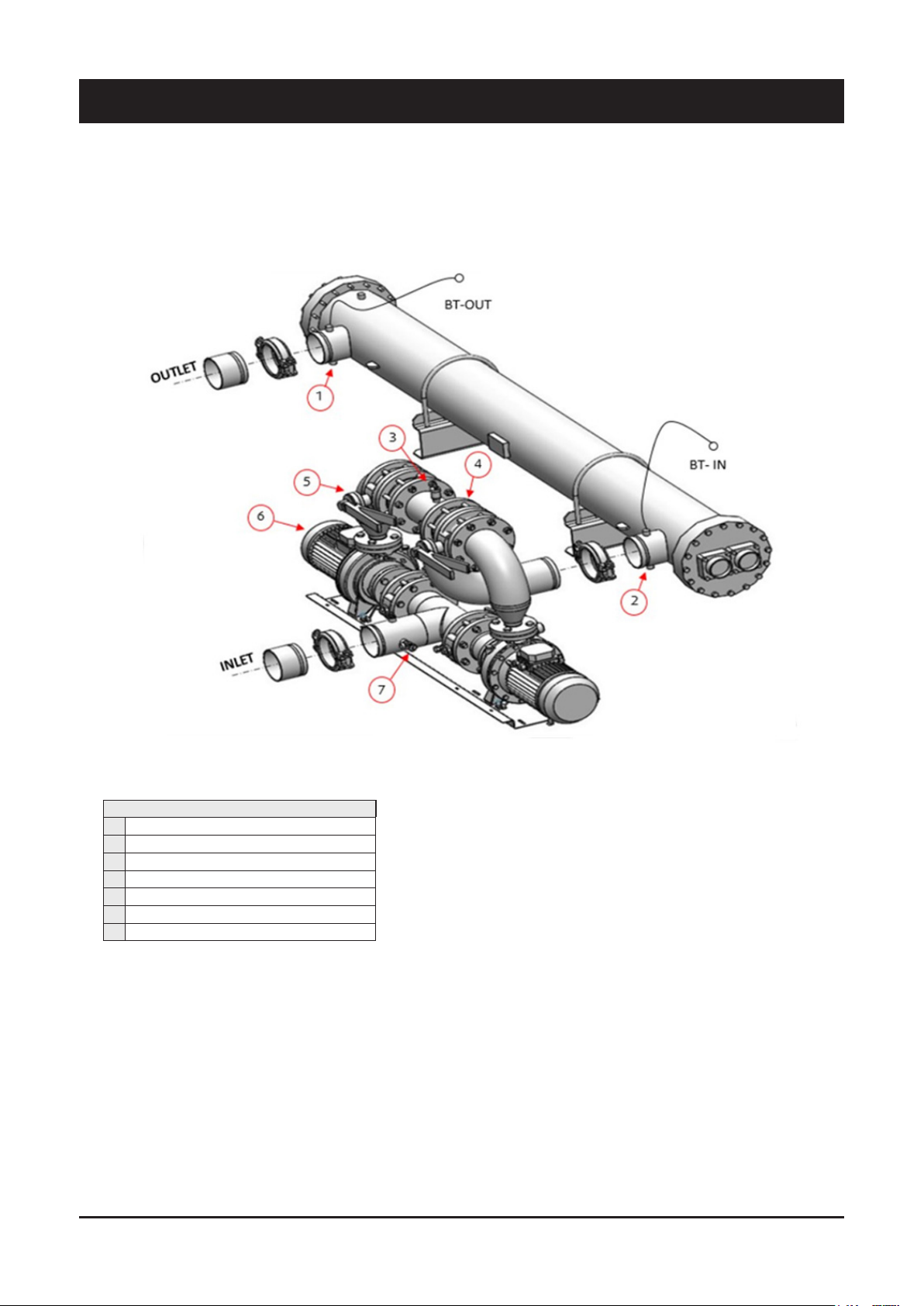
4.6 Water connections for unit provided with
hydraulic option
In case of hydraulic option installed (single/double pump), the water
inlet/outlet fittings shall conform to the instructions provided by the
plates affixed near the connection points.
General hydraulic layout with pump/s installed is shown in the image
below.
DESCRIPTION
1 Pressure transducer (Outlet of HE)*
2 Pressure transducer (Inlet of HE)*
3 Air vent
4 Non-return valve
5 Butter fly valve
6 Pump
7 Safety valve
* Only for Variable flow hydraulic module
18
Page 20
4 - Installation (continued)
4.7 Power supply
Before carrying out any operations on the
electrical system, make sure that the unit is
DANGER
DANGER
DANGER
The manufacturer may not be held liable for any damage and/or
injury caused by failure to comply with these precautions.
The unit conforms to EN 60204-1.
The following connections shall be provided:
n A 3-phase and grounding connection for the power supply
circuit.
n The electrical distribution system shall meet the power absorbed
by the appliance.
n The disconnecting and magnetothermal switches must be sized to
control the starting current of the unit.
n The power supply lines and the insulation devices must be
designed in such a way that every line independent.
n It is recommended to install differential switches, to prevent any
damage caused by phase drops.
n The fans and compressors are supplied through contactors
controlled from the control panel.
n Each motor is provided with an internal safety thermal device
and external fuses.
n The power supply cables must be inserted into dedicated
openings on the front of the unit, and the will enter the electrical
board through holes drilled on the bottom of the board.
deenergised.
It is important that the appliance is grounded.
The company in charge of the installation shall
conform to the standards applicable to outdoor
electrical connections.
4.8 Electrical connections
The unit must be installed on site according to the Machinery
Directive 2006/42/EC, Electromagnetic Compatibility Directive
2014/30/EU - as per EN 55011, Group 1, Class A, Pressure
Equipment Directive 2014/68/EU and the usual procedures and
standards applicable in the place of installation.
This equipment is intended only for industrial
applications and must be installed on side
according to the standards mentioned above
WARNING
The installar is responsible for ensuring the correct electrical
installation and the use of correct materials.
WARNING
The unit must not be operated if its installation has not been
carried out according to the instructions provided in this manual.
The power supply lines must consist of insulated copper
conductors, dimensioned for the maximum absorbed current.
Connection to terminals must be performed according to the diagram
of connections (User’s Terminal Box) provided in this manual and
according to the wiring diagram which accompanies the unit.
WARNING
For 3-phase systems, check also that the unbalance between the
phases does not exceed 2%. To perform this check, measure the
differences between the voltage of each phase couple and their mean
value during operation.
The maximum % value of these differences (unbalance) must not
exceed 2% of the mean voltage.
and according also to the usual procedures and
standards applicable in the place of installation.
Incorrect electrical installation and/or using
incorrect materials may cause additional
radio frequency emissions which may require
mitigation measures
Before connecting the power supply lines, check
that the available voltage value does not exceed
the range specified in the Electric Data (Chapter
8).
English
If the unbalance is unacceptable, contact the Energy Distributor to
solve this problem.
Supplying the unit through a line whose
unbalance exceeds the permissible value will
WARNING
automatically void the warranty.
19
Page 21
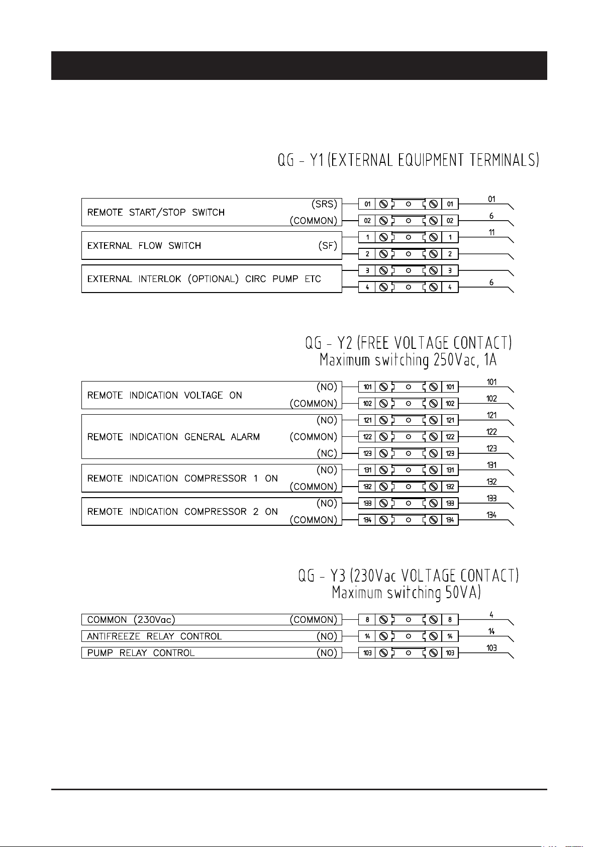
Electrical connections
4 - Installation (continued)
20
Page 22
5 - Start-Up
The unit must be started for the first time by
personnel suitably trained by one Authorised
Service Centre. Failure to meet this requirement
WARNING
will immediately void the warranty.
The operations carried out by authorised
personnel are limited to the start-up of the unit,
and do not include any other operation on the
plant, such as, for example, electrical and
hydraulic connections etc.
NOTE
All the other operations before start-up, including
oil pre-heating for at least 12 hours, must be
performed by the Installer.
5.1 Preliminary check
The checks listed below shall be performed before star ting the unit
and before the arrival of the personnel authorised.
n Check the section of power supply and grounding cables; make
sure that terminals are tightened and check the correct operation
of contactors, with the main switch open.
n Check that any voltage and phase variation in the power supply
does not exceed the prefixed thresholds.
n Connect the contacts of the flow switch and the thermal relay of
the pump and of the other devices (if any), to terminals 1-2 and
3-4, respectively.
n Check that the components of the external water circuit (pump,
user equipment, filters, power supply tank and reservoir, if any)
have been installed properly, and according to the manufacturer’s
instructions.
n Check the filling of the hydraulic circuits, and make sure that
the fluid circulation is correct, without any trace of leaks and air
bubbles. If you use ethylene glycol as antifreeze, check that its
percentage is correct.
n Check that the direction of rotation of the pumps is correct, and
that fluids have been circulating for at least 12 hours for both
pumps. Then, clean the filters on the suction side of the pumps.
n Adjust the liquid distribution network in such a way that the flow
rate is within the specified range.
n Check that the water quality is up to the specifications.
n Check that oil heaters, if any, have been turned on at least 12
hours before.
n Start the pump and check that the water flow is correct.
n Set the desired fluid temperature on the control board.
n Start the appliance (see Chapter 6).
n Check the correct direction of rotation of compressors. Scroll
compressors cannot compress the refrigerant when they rotate
in the opposite direction. To make sure that they are rotating in
the correct direction, simply check that, just after the star t-up
of the compressor, the pressure drops on the LP side and rises
on the HP side. Furthermore, if a scroll compressor rotate in
the opposite direction, there is a considerable rise in the sound
level of the unit, as well as in a dramatic reduction of current
absorption compared to normal values. In case of wrong
rotation, the scroll compressor can be definitely damaged. Phase
monitor is assembled in the unit as a standard to prevent wrong
compressors rotation.
n After about 15 minutes of operation check that there are no
bubbles, through the sight glass on the liquid line.
The presence of bubbles may indicate that a
part of the refrigerant charge has been released
in one or more points. It is important to remove
WARNING
n Repeat the start-up procedure after removing the leaks.
n Check the oil level in the compressor’s sight glass.
these leaks before proceeding.
5.3 Checking the operation
Check the following:
n The temperature of the water entering the evaporator.
n The temperature of the water leaving the evaporator.
n The level of the water flow rate in the evaporator, if possible.
n The current absorption upon the start of the compressor and in
case of stabilised operation.
n The fan’s current absorption.
Check that the condensing and evaporation temperatures, during
operation at high and low pressure detected by the pressure gauges
of the refrigerant, are within the following range:
(On the units not provided with HP/LP pressure gauges for the
refrigerant, connect a pressure gauge to the Shrader valves on the
refrigeration circuit).
English
5.2 Start-up
Start-up sequence:
n Turn on the Main switch (at least 12 hours before).
n Check that the oil in the compressor has reached the requested
temperature (the minimum temperature outside the pan must be
approx. 40°C) and that the auxiliary control circuit is energised.
n Check the operation of all the external equipment, and make sure
that the control devices of the plant are properly calibrated.
HP side
LP side
Approx. 15 to 21 °C above the temperature of
the air entering the condenser.
Approx. 2 to 7 °C below the temperature of the
leaving chilled water.
5.4 Delivery to the customer
n Train the user according to the instructions provided in Section 6.
21
Page 23
6.1 General information
6 - Control
Introduction
This document contains the information and the operating instructions
for 2 screw compressors (step type and inverter driven type).
This information is for the after-sales service and the production
operators, for the end-of-line testing.
Main characteristics
– Microprocessor control
– User-friendly keyboard
– Proportional and integral control of the return water temperature
or leaving water temperature (LWT or RWT)
– Access code to enter the Service Level
– Access code to enter User Level
– Basic functions without access code
– Alarm and LED
– Backlighted LCD
– Rotation of the compressor operation
The control system consists of:
a) Main Board. The units are provided with a microprocessor card
which is fully programmed by default for the control of a chiller
of cold only type with 2 circuits, 1 compressor for circuit, a HP
transducer and a LP transducer for Circuit.
b) EEV controllers (two separate drivers) for the management of the
electronic expansion valves.
C) Keyboard & Display Terminal.
– Oil return function - Standard for the inverter compressor,
optional (oil switch device) for step compressor
– Night mode (or Low Noise) control
– Counting of the pump/compressors’ hours of operation
– Display of discharge and suction pressure values
– Display of temperature sensor
– History of stored alarms (option)
– Built-in serial communication RS485 port with Modbus protocol
to connect the main board to a BMS network.
This built-in port is available as standard only in the case no
extra network control systems (netTune) are selected with the
units.
– Built-in serial communication Ethernet port with two possible
protocols (Modbus or Bacnet, in case also at the same time). In
case of Bacnet communication protocol it is needed to activate a
license.
– Custom protocols are available on request
The following accessories can be also connected:
– Remote Display Terminal.
The terminal makes it possible to carry out the following operations:
– the change of the main operating parameters
– the display of the detected alarms
– the display of all the measured quantities
The terminal and the card are connected by a 6-way phone cable.
The connection of the terminal to the basic card is not essential for
the normal operation of the controller.
22
Page 24
6 - Control (continued)
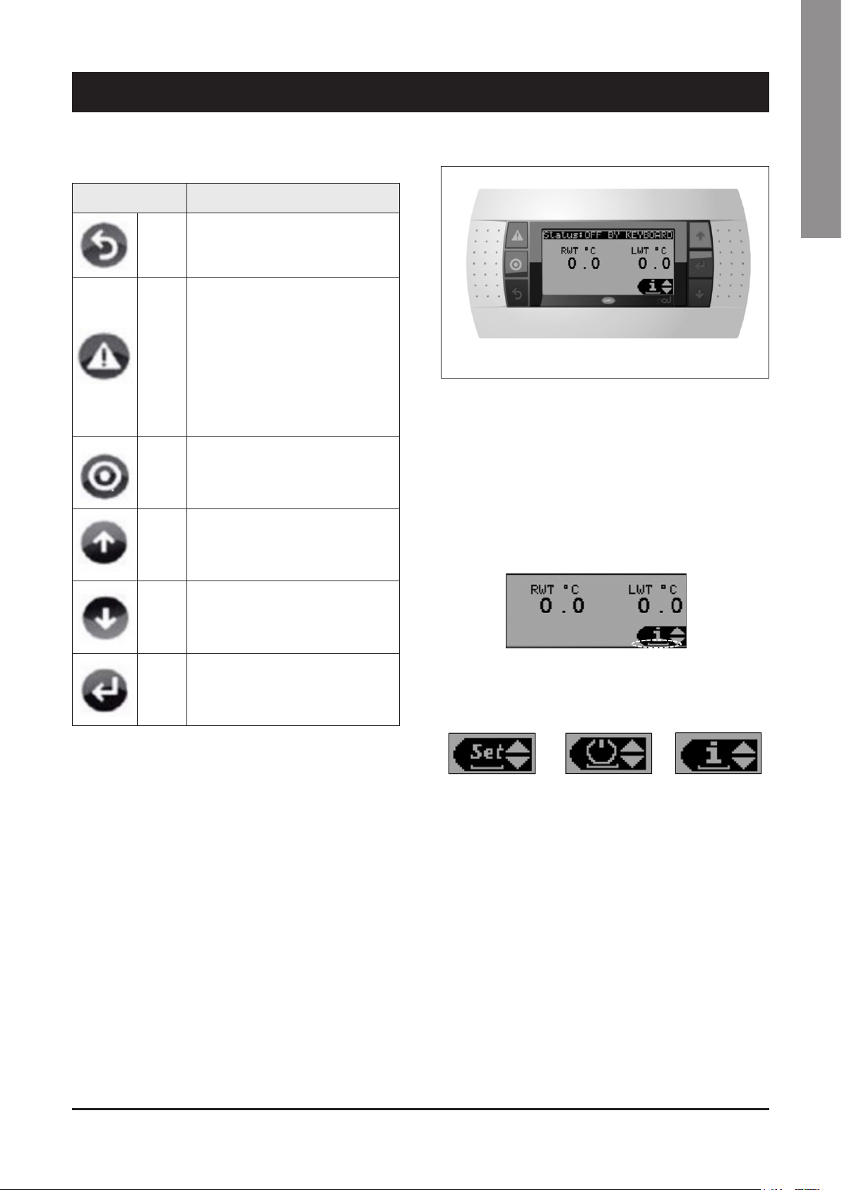
Keypad Functions
BUTTON DESCRIPTION
ESC Move back from one mask to higher level menu
ALARM
PRG Used to enter in the main menu tree
UP
Press it to enter in
a) Alarm Status
a.1) Press again to reset each single alarm,
if present (one by one)
a.2) Scroll down up to the end of the alarm
list (if an alarm list is present) and keep
pressed it for 3 second to reset all alarms
in one time
b) Alarm Data logger
Scroll a list upwards or increase a value
highlighted by the cursor
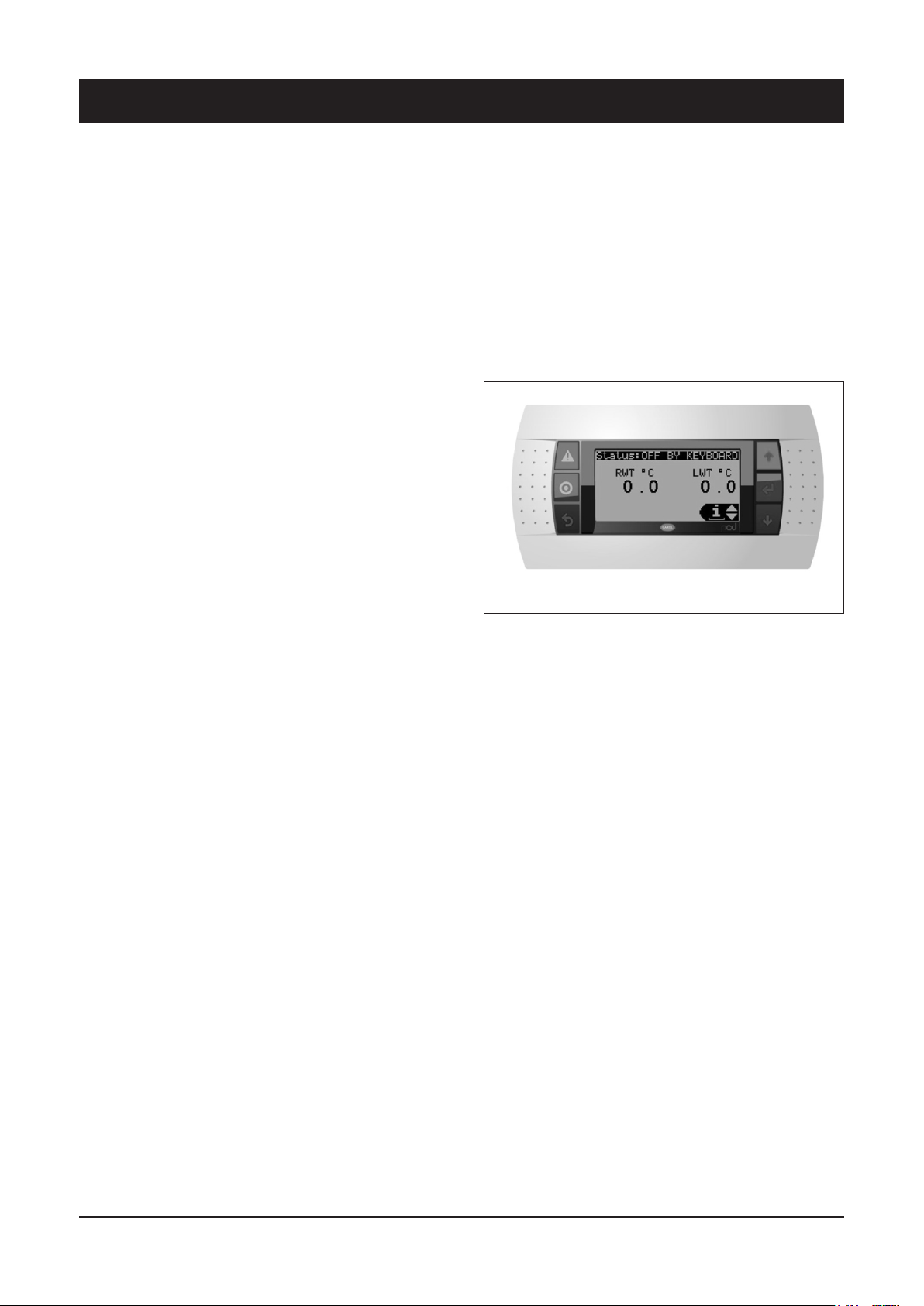
6.2 Display/Keyboard
The display is an LCD 8 lines x 22 columns. The quantities and the
information about the operation of the unit are alternated in the form
of subsequent screens, named “masks”.
It is possible to move inside the masks with the terminal keys as
described below.
6.3 Main Control Functions
In the main mask the cursor flashes at the bottom right corner of the
display, in correspondence of the Quick Menu.
English
DOWN
ENTER
Scroll a list downwards or decrease a value
highlighted by the cursor
Enter in the selected menu or confirm a value
highlighted by the cursor
By pressing UP/DOWN keys, it is possible to select the following
items of the Quick Menu.
Setting On/Off Information
23
Page 25
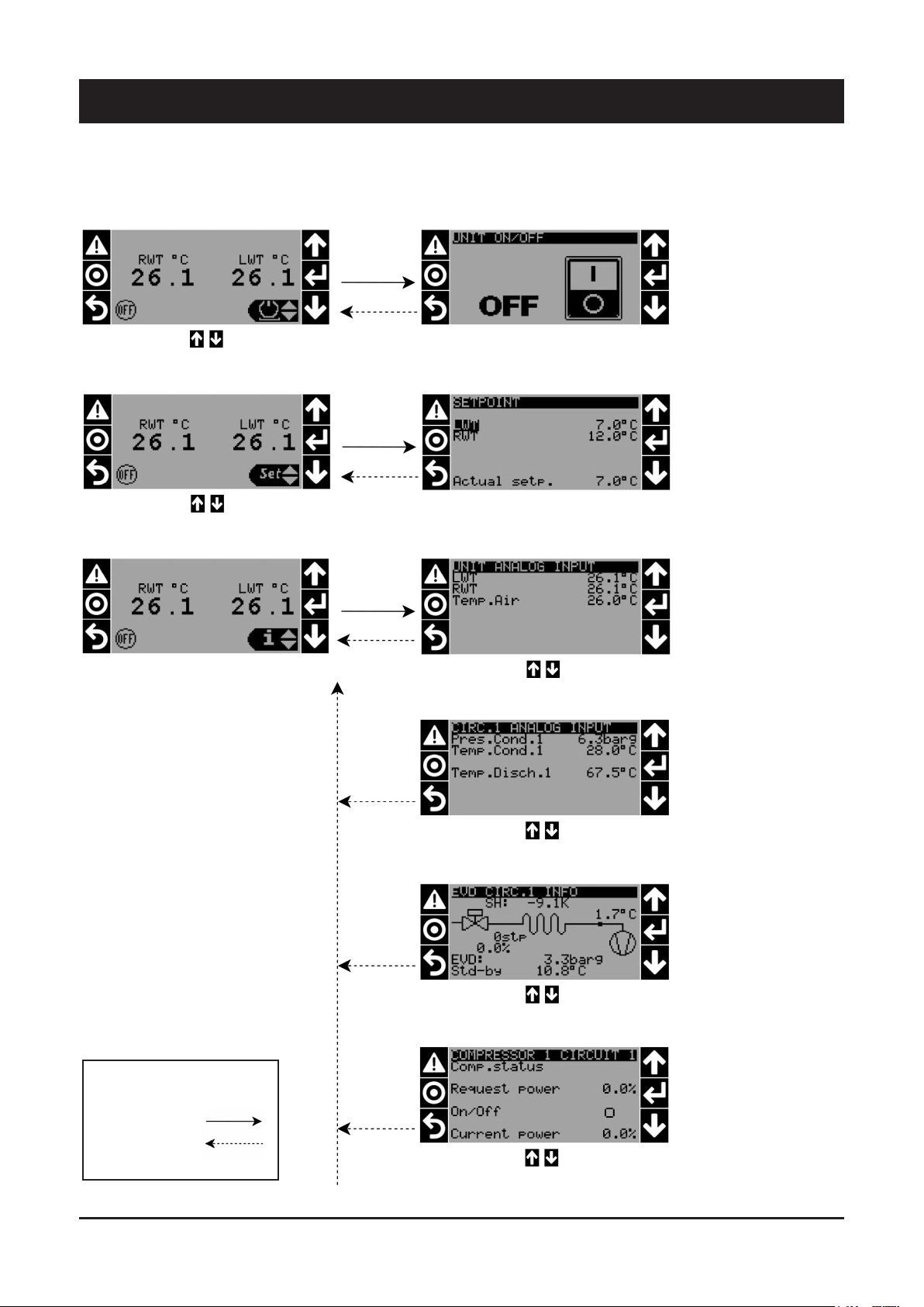
6 - Control (continued)
MAIN MASK TREE
POWER
UP and DOWN key to
switch unit ON and OFF
SETPOINT
LWT/RWT setpoints can
be modified in a range
decided by manufacturer.
The Actual Setp. is the
setpoint of regulation for
actual working mode.
READINGS
Water Outlet Temperature
Water Inlet Temperature
Outdoor Air Temperature
READINGS CIRC.1
Condensating Pressure
Saturated Condensating
Pressure
Discharge Temperature
READINGS CIRC.1
Main readings about
evaporating pressure/
temperature, superheat
and opening of the
electronic valve both in
steps and percentage.
Legenda:
Proceed forward
Go back
READINGS CIRC.1
Compressor Status info:
Power Request by regulator
On/off
Current Power given by
compressor
24
Page 26

6 - Control (continued)
English
READINGS CIRC.1
Compressor Status info:
Actual functioning status of
compressor
READINGS CIRC.1
Compressor Status info:
Options status inactive /
(active)
READINGS CIRC.1
Absorbed current read by TA
Theorical capacity of
compressor depending on
aboserbed current
READINGS CIRC.1
Actual fans speed in
percentage divided into same
groups shown on electrical
scheme.
READINGS CIRC.1
Condensating Pressure
Saturated Condensating
Pressure
Discharge Temperature
25
READINGS CIRC.2
Main readings about
evaporating pressure/
temperature, superheat and
opening of the electronic valve
both in steps and percentage.
Page 27

6 - Control (continued)
READINGS CIRC.2
Compressor Status info:
Power Request by regulator
On/off
Current Power given by
compressor
READINGS CIRC.2
Compressor Status info:
Actual functioning status of
compressor
READINGS CIRC.2
Compressor Status info:
Options status inactive /
(active)
READINGS CIRC.2
Absorbed current read by TA
Theorical capacity of
compressor depending on
aboserbed current
READINGS CIRC.2
Actual fans speed in
percentage divided into
same groups shown on
electrical scheme.
26
UNIT DIGITAL INPUTS
Status open/close of digital
inputs.
Page 28

6 - Control (continued)
English
DIGITAL INPUTS CIRC.1
Status open/close of digital
inputs related to circuit 1.
DIGITAL INPUTS CIRC.2
Status open/close of digital
inputs related to circuit 2.
UNIT DIGITAL OUTPUTS
Status open/close of digital
outputs.
DIGITAL OUTPUTS CIRC.1
Status open/close of digital
outputs related to circuit 1.
DIGITAL OUTPUTS CIRC.2
Status open/close of digital
outputs related to circuit 2.
27
SOFTWARE INFORMATION
Name and version of the
software installed in the unit
and also versions of main
firmwares.
Page 29

6 - Control (continued)
HARDWARE INFO
Basic informations and
actual IP address of the
main board.
HOURS COUNTERS
Working hours counters
of the main components
of the unit and of the unit
itself.
UNIT INFORMATIONS
Informations about actual
date/time, when it occured
the last power off of the
unit, how much time it
assed since the unit was
turned off last time.
Every digit of the password
can be modified by up/down
key to the desired value
USER PASSWORD
MAIN MENU
Several sub-menu at disposal:
A. Unit configuration
B. Parameters configuration
C. Pump
D. Compressor
E. EEV
F. Fan
G. Setting
H. Safety
I. Alarm log
L. Logout
Use UP/DOWN keys to select the desired menu and press
ENTER to access it.
For User only some sub-menu are accessible.
28
Page 30

6 - Control (continued)
SETTING MENU
Several sub-menu at disposal:
1. Options
2. Date/Time
3. Language
4. Serial Ports
5. Pwd Change
6. Initialization
7. UoM
Use UP/DOWN keys to select the desired menu and press ENTER to access it.
For User only some sub-menu are accessible.
DATE/TIME SUB-MENU
English
Settable format and
actual date/time.
LANGUAGE SUB-MENU
ALARM LOG MENU
TIME ZONE
Settable time zone to
have automatic update
of timing respect to
installation site.
Settable language for
software masks.
In case of alarms
occured since the
last memory cleared,
then it shows a full
list of alarms occured
with date/time and
identification number of
the alarm.
LOGOUT MENU
29
Press ENTER to log out
from user menu.
Page 31

6 - Control (continued)
ALARM TREE
NO ALARMS ACTIVE ALARMS ACTIVE
Press ALARM key for 3
second to reset alarm
if the cause which
generated the alarm is
solved.
In presence of more
than one active alarm:
press ALARM key for
3 second to reset all
alarms (if causes which
generated the alarm are
solved).
Press ENTER key to access to
Alarm Log Menu
30
Page 32

6 - Control (continued)
List of parameters - IN/OUT MENU
Notes:
n° circuits : 2
compressor circuit 1: fixed speed step screw
compressor circuit 2: variable speed (inverter driven) screw
Variable Name Type Description
U1
U2
U3
U4
U5
U6
U7
U8
U9
U10
Variable Name Type Description
ID1
ID2
ID3
ID4
ID5
ID6
ID7
ID8
ID9
ID10
ID11
ID12
ID13H
ID14H
ID15
ID16
ID17
ID18
Ntc
4-20mA
4-20mA
Ntc
Ntc
-
-
Ntc-HT
Ntc-HT
24Vdc
24Vdc
24Vdc
24Vdc
24Vdc
24Vdc
24Vdc
24Vdc
24Vdc
24Vdc
24Vdc
24Vdc
230Vdc
230Vdc
24Vdc
24Vdc
24Vdc
24Vdc
English
ANALOG INPUTS - control board
Leaving / Outlet water temperature
Pressure from high pressure transducer 1
Pressure from high pressure transducer 2
Entering / Inlet water temperature
Outdoor air temperature
Not used
Not used
Not used
Discharge probe temperature circuit 1
Discharge probe temperature circuit 2
DIGITAL INPUTS - control board
Remote On/Off Status
Low pressure switch circuit 1 Status
Low pressure switch circuit 2 Status
Not used
Serious Alarm (phase monitor) Status
Thermal protection compressor 1 Status
Oil level switch compressor 1 Status
Not used
Not used
Not used
Not used
Water flow switch / Interlock Status
High pressure switch comrpessor 1
Not used
Thermal protection fan circuit 1 step 2 Status
Thermal protection fan circuit 1 step 1 Status
Thermal protection fan circuit 2 step 2 Status
Thermal protection fan circuit 2 step 1 Status
INPUTS / OUTPUTS - expansion card
Variable Name Type Description
U1
U2
U3
U4
U5
U6
U7
U8
U9
U10
-
-
-
-
-
-
-
-
-
-
Remote double set point
Part load / switch off Circuit 1
Part load / switch off Circuit 2
Thermal shared fan deck
Not used
Not used
Shared fan deck (control signal)
Analog remote set point
Not used
Not used
31
Page 33

6 - Control (continued)
List of parameters - IN/OUT MENU (continued)
ANALOG OUTPUTS - control board
Variable Name Type Description
Y1
Y2
Y3
Y4
Y5
Y6
Variable Name Type Description
NO1
NO2
NO3
NO4
NO5
NO6
NO7
NO8
NO9
NO10
NO11
NO12
NO13
NO14
NO15
NO16
NO17
NO18
0/10Vdc
0/10Vdc
0/10Vdc
0/10Vdc
0/10Vdc
0/10Vdc
DIGITAL OUTPUTS - control board
SPST
SPST
SPST
SPST
SPST
SPST
SPST
SPDT
SPST
SPST
SPST
SPDT
SPDT
SPDT
SPDT
SPST
SPST
SPST
Inverter fans Circuit 1 Step 2
Inverter fans Circuit 1 Step 1
Inverter fans Circuit 2 Step 2
Inverter fans Circuit 2 Step 1
Inverter pump evaporator
Not used
Evaporator heater status
Compressor 1 Circuit 1 Solenoid CR1 status
Compressor 1 Circuit 1 Solenoid CR2 status
Compressor 1 Circuit 1 Solenoid CR3 status
Compressore 1 circuito 1 PartWindingA status
Compressore 1 circuito 1 PartWindingB status
Pump status
Alarm status
Not used
Not used
Compressor cranckase heater status
Not used
Not used
Not used
Circuit 1 fans step 2 (group with fans > ) Status
Circuit 1 fans step 1 (group with fans < ) Status
Circuit 2 fans step 2 (group with fans > ) Status
Circuit 1 fans step 1 (group with fans < ) Status
DIGITAL OUTPUTS * - expansion card
Variable Name Type Description
NO1
NO2
NO3
NO4
NO5
NO6
-
-
-
-
-
-
ECO valve system 1 status
ECO valve system 2 status
Liquid injection valve system 1 status
Not used
Share fan deck fans (on-off) status
Not used
32
Page 34

6 - Control (continued)
Alarms
Alarm code Description Type Notes
0
1
2
3
4
5
6
7
8
9
10
11
12
13
14
15
16
17
18
19
20
21
22
23
24
25
26
27
28
29
30
31
32
33
34
35
36
37
38
39
40
41
42
43
44
45 High suction pressure Comp 1 Circuit 2
46 Low suction pressure Comp 1 Circuit 2
47 High current Comp 1 Circuit 2
48 High ratio pressure Comp 1 Circuit 2
49 Low ratio pressure Comp 1 Circuit 2
50 Low delta pressure Comp 1 Circuit 2
51 High discharge pressure Comp 1 Circuit 2
52 LOP - EEV Valve A circuit 2
53 LOP - EEV Valve B circuit 2
54 MOP - EEV Valve A circuit 2
55 MOP - EEV Valve A circuit 2
56 EEV A Motor Error circuit 2
57 EEV B Motor Error circuit 2
58 Low suction temperature EEV valve A Circuit 2
59 Low suction temperature EEV valve B Circuit 2
60
61
Error in the number of retain memory writings
Error in retain memory writings
Water Flow Switch / Interlock
Phase monitor alarm
Antifreeze
High difference RWT/LWT
Wrong trend RWT/LWT
Returning water temperature probe
Leaving water temperature probe
Discharge pressure transducer circuit 1
Discharge pressure transducer circuit 2
External air temperature probe
Discharge temperature probe circuit 1
Discharge temperature probe circuit 2
High discharge temperature Comp 1 Circuit 1
Low discharge pressure Comp 1 Circuit 1
High suction pressure Comp 1 Circuit 1
Low suction pressure Comp 1 Circuit 1
High current Comp 1 Circuit 1
High ratio pressure Comp 1 Circuit 1
Low ratio pressure Comp 1 Circuit 1
Low delta pressure Comp 1 Circuit 1
High discharge pressure Comp 1 Circuit 1
LOP - EEV Valve A Circuit 1
LOP - EEV Valve B Circuit 1
MOP - EEV Valve A Circuit 1
MOP - EEV Valve B Circuit 1
EEV A Motor Error Circuit 1
EEV B Motor Error Circuit 1
Low suction temperature EEV valve A Circuit 1
Low suction temperature EEV valve B Circuit 1
High condensing temperature Circuit 1
Suction pressure transducer circuit 1
Suction temperature probe circuit 1
S3 probe circuit 1
S4 probe circuit 1
Battery low charge EVD circuit 1
EEPROM Alarm EVD circuit 1
Incomplete closing EVD circuit 1
Emergency closing EVD circuit 1
Firmware not compatible EVD circuit 1
Configuration Error EVD circuit 1
Offline EVD circuit 1
High discharge temperature Comp 1 Circuit 2
Low discharge pressure Comp 1 Circuit 2
High condensing temperature Circuit 2
Suction pressure transducer circuit 2
User reset
User reset
Auto reset until counter
Auto reset
User reset
Auto reset
Auto reset
Auto reset
Auto reset
Auto reset
Auto reset
Auto reset
Auto reset
Auto reset
User reset
User reset
User reset
User reset
User reset
User reset
User reset
User reset
User reset
Auto reset
Auto reset
Auto reset
Auto reset
Auto reset
Auto reset
Auto reset
Auto reset
Auto reset
Auto reset
Auto reset
Auto reset
Auto reset
Auto reset
Auto reset
Auto reset
Auto reset
Auto reset
Auto reset
Auto reset
Auto reset
Auto reset
Auto reset
Auto reset
Auto reset
Auto reset
Auto reset
Auto reset
Auto reset
Auto reset
Auto reset
Auto reset
Auto reset
Auto reset
Auto reset
Auto reset
Auto reset
Auto reset
Auto reset
English
33
Page 35

6 - Control (continued)
Alarm code Description Type Notes
62
63
64
65
66
67
68
69
70
71
72
73
74
75
76
77
78
79
80
81
82
83
84
85
86
87
88
89
90
91
92
93
94
95
96
97
98
99
100
101
102
103
104
(*) The Inverter Compressor alarms (critical and fault) must be resetted with support of Systemair Service personnel. Call your Service Center by providing the
Alarm/Fault code shown on the controller display in order to make possible a further analysis of the problem occurred.
(**) Alarm/Fault code shown in the pump inverter display. After auto reset (2 times) the manual reset is possible from pump inverter display
Suction temperature probe circuit 2
S3 probe circuit 2
S4 probe circuit 2
Battery low charge EVD circuit 2
EEPROM Alarm EVD 2
Incomplete closing EVD circuit 2
Emergency closing EVD circuit 2
Firmware not compatible EVD circuit 2
Configuration Error EVD circuit 2
EVD offline EVD circuit 2
Pcoe 1 offline
Wrong configuration on Pcoe 1
Low pressure switch circuit 1
Low pressure switch circuit 2
Overload compressor 1 circuit 1
High pressure switch circuit 1
Oil level switch circuit 1
Overload fan deck 1 circuit 1
Overload fan deck 2 circuit 1
Overload fan deck 1 circuit 2
Overload fan deck 2 circuit 2
High pressure switch circuit 2
Oil level switch circuit 2
Overload compressor 1 circuit 2
Low superheat alarm EEV valve A circuit 1
Low superheat alarm EEV valve B circuit 1
Low superheat alarm EEV valve A circuit 2
Low superheat alarm EEV valve B circuit 2
Overload fan deck shared
Current transformer circuit 1
Current transformer circuit 2
Maintenance hours compressor 1 circuit 1
Maintenance hours compressor 1 circuit 2
Compressor 1 circuit 1 offline (Inverter)
Compressor 1 circuit 2 offline (Inverter)
Returning water temperature probe
Leaving water temperature probe
Compressor 1 circuit 1 Critical (Inverter)
Compressor 1 circuit 1 Fault (Inverter)
Compressor 1 circuit 2 Critical (Inverter)
Compressor 1 circuit 2 Fault (Inverter)
Pump Inverter Alarm
Pump Inverter Fault
Auto reset
Auto reset
Auto reset
Auto reset
Auto reset
Auto reset
Auto reset
Auto reset
Auto reset
Auto reset
Auto reset
Auto reset
Auto reset until counter
Auto reset until counter
User reset
User reset
User reset
User reset
User reset
User reset
User reset
User reset
User reset
User reset
Auto reset
Auto reset
Auto reset
Auto reset
User reset
Auto reset
Auto reset
User reset
User reset
Auto reset
Auto reset
Auto reset
Auto reset
Manual reset (*)
Manual reset (*)
Manual reset (*)
Manual reset (*)
Auto reset (2 times only) (**)
Auto reset (2 times only) (**)
INVERTER PUMP ALARM LIST
S.NO. WARNING NO. DESCRIPTION
1
2
3
4
5
6
7
8
9
10
11
12
13
14
15
W/A2
W/A7
W/A8
W/A9
W/A10
W/A11
W/A12
W/A27
W/A35
W/A37
A4
A13
A14
A29
A30
DC over voltage
DC under voltage
Inverter overloaded
Motor ETR over temperature
Motor thermistor over temperature
Brake chopper short-circuited
Out of frequency range
Phase Imbalance
Mains phase loss
Drive over temperature
Motor phase U missing
Live zero error
Torque limit
Over Current
Ground fault
34
S.NO. WARNING NO. DESCRIPTION
16
17
18
19
20
21
22
23
24
25
26
27
28
29
30
A31
A32
A47
A65
A244
A16
A33
A38
A39
A45
A46
A48
A69
A79
A91
Motor phase V missing
Motor phase W missing
24 V supply low
Control Board Over-temperature
Heatsink temp
Short Circuit
Inrush fault
Internal fault
Heatsink sensor
Earth fault 2
Pwr. card supply
1.8 V supply low
Pwr. Card Temp
Illegal PS config
Analog input 54 wrong settings
Page 36

6 - Control (continued)
6.4 Setpoint
Pressing the Set key allows you to enter the Set point level accessible to the user. The parameters that can be set are listed below, along with the
limit values and the default values (standard shop settings):
User parameters Control mode Min value Max value Default
Cooling Setpoint
Cooling Setpoint - glycol water 10%
Cooling Setpoint - glycol water 40%
6.5 Protection and Safety Equipment
Refrigeration system
The units are filled with R134a/R513A refrigerant fluid of non
hazardous type (group II). Safety device (pressure switch and safety
valves) with the sets below indicated are provided on the discharge
and suction line of each circuit.
Discharge Line
Pressure relief valve 22 bar.
Pressure switch 19,7 bar.
Suction line
Pressure relief valve 14.5 bar.
Pressure switch 0.5 bar.
RWT Return Control 8 18 12
LWT Leaving Control 5 15 7
RWT Return Control 3 18 12
LWT Leaving Control 0 15 7
RWT Return Control -5 18 12
LWT Leaving Control -8 15 7
Compressor protection
Compressors are equipped with a heating element to prevent
oil dilution, which may result in remarkable risks of failure of
compressors.
The windings of the compressors’ motors are provided with a
thermal protection.
An accessory kit for thermal protection (ACB) is available, for any
overcurrent of compressors, which shall be shop-mounted.
Electrical flow switch
A electrical flow switch must be installed, to prevent the unit working
in case of insufficient circulation of the chilled fluid.
English
Frost Protection for the Chilled Fluid
These units are provided with frost protection for the chilled fluid. This
protection consists of an electrical resistor positioned in contact with
the coolant/circulating fluid exchanger, which is activated (although
the unit is off) when the temperature of the fluid drops below 5 °C the standard value for a non-glycol unit.
If the leaving water temperature drops below 4 °C (standard value for
a non-glycol unit) the machine’s antifreeze alarm is activated. If the
circulating fluid is water, before the beginning of the cold season it is
advisable to drain the circuit to prevent water frosting.
If the circuit cannot be drained, it is essential to avoid de-energizing
the unit, so as to permit the activation, when necessary, of the frost
protection.
The electrical flow switch must be carefully
installed, according to the instructions given by
WARNING
The electrical flow switch must be installed on the pressing side
of the circulation pump for the fluid, just upstream of the heat
exchanger’s inlet. The electrical flow switch must be installed in a
horizontal straight length of piping, in a position reasonably far (both
upstream and downstream) from localized pressure drops (curves,
valves etc.).
the Manufacturer.
Continuous Regulation of the EC brushless fans
EC brushless fans are mounted as standard and allow the unit to
work at an ambient temperature down to -10 °C.
35
Page 37

6 - Control (continued)
6.6 HPF version configuration
Units equipped with High pressure fan (HPF) can be set-up on the
field to give the unit a specific static pressure.
By entering parameter in service level - Max Speed (Vdc) - it is
possible to modify high static pressure. The table below shows
the correspondance between chiller model, fan RPM, high static
pressure (approximate values).
Model Fan Static Pressure (Pa) Fan RPM
0 900 6,9
30 950 7,3
380-1260
70 1.000 7,9
100 1.050 8,3
120 1.100 10,0
Parameter in Service Level:
Max Speed (Vdc)
36
Page 38

7 - Product Description
7.1 Introduction
The units are air cooled water chillers provided with screw
compressors with two refrigeration circuits.
These units are fit for cooling intermediate fluids (glycoled water), for
air-conditioning applications in industrial processes.
VERSION (1) DESCRIPTION
Standard version
Super Low Noise version (S)
High pressure fan (HPF) (1)
High Temperature version (HT) (1)
(1) A high pressure fan (HPF) version and High Temperature (HT) version are equipped with extra powered brushless fans, able to work up to
1100 Rpm.
Brine Version: Unit with dedicated devices on refrigeration system allows the units to operate with brine (ethylenic or propylenic glycol) down to -8 °C.
Available options:
OPTIONS DESCRIPTION
Desuperheater (D) The heat recovery is carried out by a desuperheater mounted on the compressor’s discharge line.
Totaly heat recovery Not available. For information, please contact commercial office.
These units can be installed outdoor on the roof of a building or at
ground level.
This series includes the following versions:
Air cooled water chillers, using R134a or R513A refrigerant.
English
7.2 General specifications
The units are supplied complete and provided with all connecting
pipes for the refrigerant and internal wiring.
The refrigeration circuit of each unit undergoes a pressure test, is
drained, vacuumised, dehydrated and filled with refrigerant, and
includes the necessary oil. Once assembled, each unit is subjected
to a complete final testing and the correct operation of all refrigeration
circuits is checked.
The base and the frame of each unit are made of very thick
galvanised sheet, and are secured by screw and stainless bolts. All
panels are secured by screw and tropicalised steel bolts, they can be
disassembled for easy access to internal components.
All galvanised steel parts are painted with white polyester resin, to
ensure the resistance of the unit to corrosion and weather agents
over time.
7.3 Compressors
The units are provided with high power, high efficiency and low
vibration level semi-hermetic screw compressors. For special
application (on request) compressors with liquid injection or external
oil cooling with plate-type exchangers can be provided to reduce the
discharge temperature.
As standard, the capacity control is of hybrid type: step type for the
fixed speed compressor and stepless type for the inverter driven
compressor. It is handled by capacity control solenoid valves,
handled by the microprocessor of the appliance.
7.4 Refrigeration circuits
The units are provided with two independent circuits with screw
compressors for each circuit and shell and tube heat exchanger.
Each refrigerant circuit includes: a service valve for refrigerant
filling, shutoff valves for suction lines (on request), as well as for
the delivery and liquid lines, an electronic expansion valve, that
completely closed (as a solenoid valve) makes it possible to start/
stop the compressor, a dehydrating car tridge filter, a sight glass with
humidity indicator.
Furthermore, each circuit is equipped with safety devices in
accordance with PED 2014/68/EU: high and low pressure switches,
safety valves providing protection in case of fire or malfunction of
compressors.
7.5 Water heat exchanger
Evaporator
The units are provided with a direct-expansion refrigerant/water shell
and tube heat exchanger with several refrigeration circuits.
The evaporators are insulated with UV ray-proof 19 mm-thick anticondensate closed-cell polyethylene material.
The external surface is provided with wire electric heaters (400-800
W), which prevent frosting at low temperatures (down to -18 °C)
when the unit is off.
The motor’s terminals are weatherproof, according to standard IP54.
37
Page 39

7 - Product Description (continued)
Desuperheater
All units are available with desuperheaters (DSH). DSH is refrigerant/
water heat exchanger with brazed plates.
DSH is fitted on the compressor discharge pipe and it’s dimensioned
to recover about the 10-15% of total rejected heat. Each unit is
equipped with 2 exchangers, one for each circuit.
Total heat recovery condenser
Some units are available with total heat recovery condenser (THRC).
THRC is refrigerant / water heat exchanger with brazed plates or shell
and tube, according to chiller size. THRC is fitted on the compressor
discharge pipe in parallel with the standard cooling circuit. The heat
recovery function is by means of a four-way valve. Each unit is
equipped with 2 exchangers, one for each circuit. Exchangers are
insulated with UV ray-proof 19 mm-thick anticondensate closed-cell
polyethylene material.
7.6 Air heat exchanger
Coils are microchannel type, made of 100% aluminum (fins, tubes
and headers). Tube and fins coils (copper/aluminium) are available
as option
7.7 Fans
The condenser’s fans are of large diameter (800 mm) axial type.
They are EC brushless type up to around 900Rpm for standard and S
versions, up to around 1100 Rpm for HT and HPF versions. They are
provided with external diffusers (nozzles), that reduce the aeraulic
motor to a large extent. Each fan is provided with galvanised steel
accident-prevention guard, painted after assembly.
Finally, the fans’ motors are completely closed, protection class
IP55, protection thermostat immersed in windings.
7.8 Electric power supply and control system
All units are provided with a microprocessor and a “Chiller Control”
system.
The electrical connection of the controls and the startup units for the
motor are carried out and tested in the factory. The power supply
and control components are separate and accessible from different
doors.
A door stop disconnecting switch is always available, and is mounted
on the door of the appliance, supply side. The cabinet includes
also another door, that can be opened from the top, waterproofed
according to IP54 standard.
The power supply compartment includes:
n
Master switch
n
Network isolator, contactors, compressor fuses
Control panel includes:
n
A transformer for auxiliaries, fuses, relay and electronic card, a
thermostat for the compressor’s delivery temperature
n
The keyboard and the display of the “Chiller-Control”
microcomputer, mounted on the door of the control section.
7.9 Accessories
List of available accessories, provided separately, to be mounted on
site by the installer:
Water flow switch
Prevents the operation of the unit when the chilled fluid is insufficient.
It is advisablem to install a flow switch, to ensure the correct
operation of the unit.
Water filter
Filter to be mounted on the suction side of the water heat exchanger.
It is mandatory to install a water filter to remove impurities from the
water suplly.
Antivibrating supports (AVM)
Isolating spring supports, equipped with bolts for fastening to
the base. They are supplied separated from the unit and must be
mounted on site by the customer, at his own expense.
Remote wall terminal
Makes it possible to check the unit through a remote terminal, up to
a maximum distance of 400 meters.
RS485 serial card (for MODBUS or BACNET)
A communication interface makes it possible to control and manage
the unit from a local station, with RS485 connection, up to a distance
of 1000 m.
It is possible to obtain the remote control and the management, by
inserting the control into the management plant of the building.
Internal hydro kits
Consist of pump(s) and relevant accessories (tank is not available
inside the unit).
Hydraulic module
"Consist of one or two centrifugal pumps standardized to EN 733,
ISO 5199 and directive 2009/125/EC. Three-phase electrical motor,
protected to IP55, insulation class F. In the case of two pumps (One
Operational and one standby), the standby pump starts once the
operational pump breaks down. "
Variable flow hydraulic module
"Consist of one or two centrifugal pumps standardized to EN 733,
ISO 5199 and directive 2009/125/EC. Three-phase electrical motor,
protected to IP55, insulation class F, coupled with an inverter
(protected to IP55), which modulates the current’s frequency
between 25 and 50 Hz. The two pumps are managed to balance their
running time. The inverter is used to manage the pumps is placed in
a dedicated panel and is driven directly by the unit’s controller. "
External hydro kits
Consist of buffer tank, pump(s), relevant accessories and with or
without tank antifreeze heater.
38
Page 40

7 - Product Description (continued)
Refrigerant flow diagram - Unit 380-510 CO
M
EEV
CONTROL
5
S
5
AT
A
A
10
BT
1B
UNIT
CONTROL
4
CIRCUIT 2
INVERTER
H
B
11
L
8
9
7
G
2
D
5
3
AF
English
M
S
55
AT
A
CIRCUIT 1
STEP
11
6
S
E
F
S
UNIT
CONTROL
A
1A
H
10
B
BT
EEV
CONTROL
4
9
8
7
G
2
D
5
5
3
AF
COMPONENTS
1A Compressor (Screw Step type)
1B Compressor (Screw Inverter type)
2 Air cooled condenser
3 Filter drier
4 Electronic expansion valve
5 Globe valve
6 Heat exchanger (Shell & Tube Type)
7 Desuperheater (Optional)
8 Muffler (Optional)
9 Anti-vibration pipe (Optional)
10 Suction compressor valve (Optional)
11 Suction accumulator (only BC version)
SAFETY / CONTROL DEVICES
A High pressure switch
AT High pressure transducer
B Low pressure switch
BT Low pressure transducer
S 5/16” Shrader connection
D Air temperature sensor
E Outlet water temperature sensor
F Inlet water temperature sensor
G PED pressure relief valve HP side
H PED pressure relief valve LP side
M Discharge temperature sensor
AF Access fitting SAE FLARE 3/8”
L Oil level switch
Pressure Pipe connection with Shrader valve
39
Page 41

7 - Product Description (continued)
Refrigerant flow diagram - Unit 440-590-660-730-810-900-980-1060-1160 CO
M
EEV
CONTROL
5
S
5
AT
A
A
15
BT
1B
UNIT
CONTROL
4
CIRCUIT 2
INVERTER
H
16
B
S
E
F
L
CIRCUIT 1
STEP+ECO
6
S
UNIT
CONTROL
H
16
B
55
AT
A
A
1A
15
BT
EEV
CONTROL
4
S
M
9
13
8
9
7
G
2
D
5
3
AF
8
7
AF
3
5
12
G
2
5
D
10
14
11
COMPONENTS
1A Compressor (Screw Step type)
1B Compressor (Screw Inverter type)
2 Air cooled condenser
3 Filter drier
4 Electronic expansion valve
5 Globe valve
6 Heat exchanger (Shell & Tube Type)
7 Desuperheater (Optional)
8 Muffler (Optional)
9 Anti-vibration pipe (Optional)
10 Solenoid valve (ECO)
11 Thermostatic expansion valve (ECO)
12 Heat exchanger (Phetype) (ECO)
13 Non return valve (ECO)
14 Sight glass (ECO)
15 Suction compressor valve (Optional)
16 Suction accumulator (only BC version)
SAFETY / CONTROL DEVICES
A High pressure switch
AT High pressure transducer
B Low pressure switch
BT Low pressure transducer
S 5/16” Shrader connection
D Air temperature sensor
E Outlet water temperature sensor
F Inlet water temperature sensor
G PED pressure relief valve HP side
H PED pressure relief valve LP side
M Discharge temperature sensor
AF Access fitting SAE FLARE 3/8”
L Oil level switch
Pressure Pipe connection with Shrader valve
40
Page 42
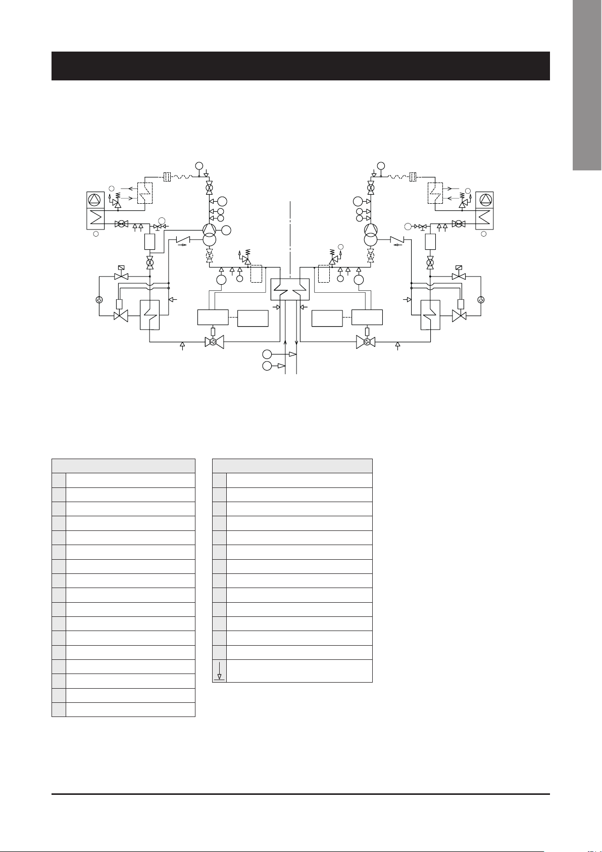
7 - Product Description (continued)
Refrigerant flow diagram - Unit 1260 CO
M
8
G
2
5
D
10
14
11
7
AF
3
5
12
S
9
5
AT
INVERTER+ECO
A
A
L
1B
13
EEV
CONTROL
4
15
BT
CIRCUIT 2
16
B
UNIT
CONTROL
English
S
M
9
8
55
H
B
AT
A
A
1A
15
BT
EEV
CONTROL
CIRCUIT 1
STEP+ECO
16
6
S
E
F
S
UNIT
CONTROL
7
AF
3
13
5
12
G
2
5
D
10
14
11
COMPONENTS
1A Compressor (Screw Step type)
1B Compressor (Screw Inverter type)
2 Air cooled condenser
3 Filter drier
4 Electronic expansion valve
5 Globe valve
6 Heat exchanger (Shell & Tube Type)
7 Desuperheater (Optional)
8 Muffler (Optional)
9 Anti-vibration pipe (Optional)
10 Solenoid valve (ECO)
11 Thermostatic expansion valve (ECO)
12 Heat exchanger (Phetype) (ECO)
13 Non return valve (ECO)
14 Sight glass (ECO)
15 Suction compressor valve (Optional)
16 Suction accumulator (only BC version)
SAFETY / CONTROL DEVICES
A High pressure switch
AT High pressure transducer
B Low pressure switch
BT Low pressure transducer
S 5/16” Shrader connection
D Air temperature sensor
E Outlet water temperature sensor
F Inlet water temperature sensor
G PED pressure relief valve HP side
H PED pressure relief valve LP side
M Discharge temperature sensor
AF Access fitting SAE FLARE 3/8”
L Oil level switch
Pressure Pipe connection with Shrader valve
41
Page 43
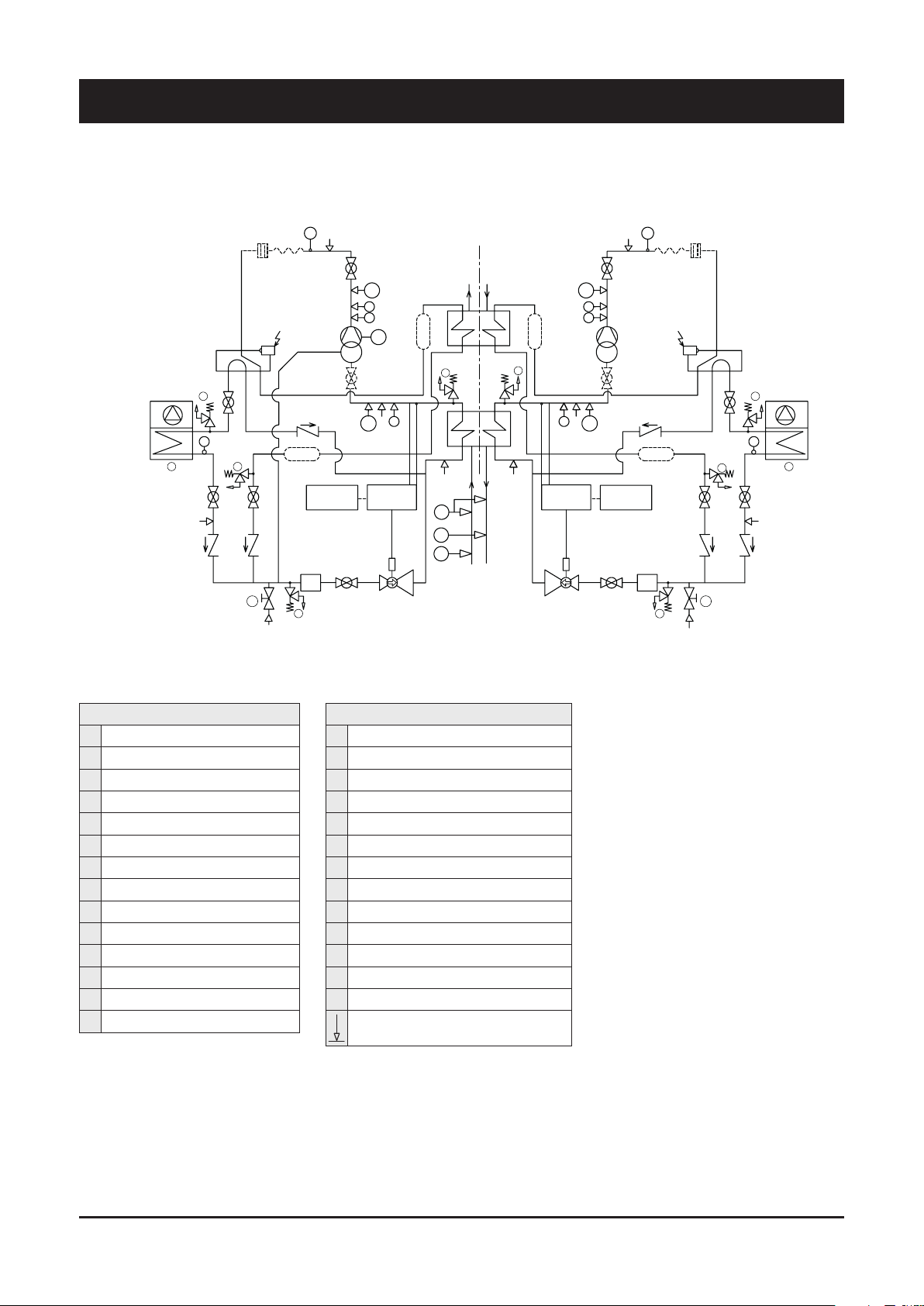
7 - Product Description (continued)
Refrigerant flow diagram - Unit 380-510 TR
8
9
M
S
5
AT
A
A
12
11
G
1B
UNIT
CONTROL
3
ON
G
2
H
D
G
5
S
12
AF
L
10
BT
EEV
CONTROL
5
CIRCUIT 2
INVERTER
B
4
M
S
9
8
CIRCUIT 1
STEP
7
H
6
S
C
E
F
1111
H
S
EEV
CONTROL
55
AT
A
A
1A
10
B
BT
UNIT
CONTROL
4
5
ON
13
G
5
12
H
11
G
5
12
3
AF
G
2
D
S
COMPONENTS
1A Compressor (Screw Step type)
1B Compressor (Screw Inverter type)
2 Air cooled condenser
3 Filter drier
4 Electronic expansion valve
5 Globe valve
6 Heat exchanger (Shell & Tube Type)
7 Heat recover (Shell & Tube Type)
8 Muffler (Optional)
9 Anti-vibration pipe (Optional)
10 Suction compressor valve (Optional)
11 Liquid receiver
12 Check valve
13 4-way valve
SAFETY / CONTROL DEVICES
A High pressure switch
AT High pressure transducer
B Low pressure switch
BT Low pressure transducer
S 5/16” Shrader connection
D Air temperature sensor
E Outlet water temperature sensor
F Inlet water temperature sensor
G PED pressure relief valve HP side
H PED pressure relief valve LP side
M Discharge temperature sensor
AF Access fitting SAE FLARE 3/8”
L Oil level switch
Pressure Pipe connection with Shrader valve
42
Page 44

7 - Product Description (continued)
Refrigerant flow diagram - Unit 440-590-660 TR
8
2
G
H
D
G
5
S
12
AF
M
9
ON
12
11
G
S
1B
UNIT
CONTROL
3
CIRCUIT 2
INVERTER
5
AT
A
A
10
BT
EEV
CONTROL
5
11 11
L
B
C
E
F
4
H
S
7
6
CIRCUIT 1
STEP+ECO
H
S
4
21
B
EEV
CONTROL
22
AT
A
A
10
BT
24
55
UNIT
CONTROL
English
M
S
1A
5
20
8
9
ON
13
G
5
12
11
23
3
G
H
G
5
12
AF
2
D
COMPONENTS
1A Compressor (Screw Step type)
1B Compressor (Screw Inverter type)
2 Air cooled condenser
3 Filter drier
4 Electronic expansion valve
5 Globe valve
6 Heat exchanger (Shell & Tube Type)
7 Heat recover (Shell & Tube Type)
8 Muffler (Optional)
9 Anti-vibration pipe (Optional)
10 Suction compressor valve (Optional)
11 Liquid receiver
12 Check valve
13 4-way valve
20 Solenoid valve (ECO)
21 Thermostatic expansion valve (ECO)
22 Heat exchanger (Phetype) (ECO)
23 Non return valve (ECO)
24 Sight glass (ECO)
SAFETY / CONTROL DEVICES
A High pressure switch
AT High pressure transducer
B Low pressure switch
BT Low pressure transducer
S 5/16” Shrader connection
D Air temperature sensor
E Outlet water temperature sensor
F Inlet water temperature sensor
G PED pressure relief valve HP side
H PED pressure relief valve LP side
M Discharge temperature sensor
AF Access fitting SAE FLARE 3/8”
L Oil level switch
Pressure Pipe connection with Shrader valve
43
Page 45

8.1 Pressure drops
Evaporator Pressure drop
8 - Technical Data
Model
380 366 63010 105016 39381 4,314E-09 17,1 47,6 6,7
450 444 76366 127277 47729 4,129E-09 24,1 66,9 9,4
500 501 86180 143633 53862 2,486E-09 18,5 51,3 7,2
590 567 97512 162519 60945 2,486E-09 23,6 65,7 9,2
660 645 110953 184922 69346 2,485E-09 30,6 85,0 11,9
730 706 121426 202376 75891 1,999E-09 29,5 81,9 11,5
810 780 134199 223666 83875 1,999E-09 36,0 100,0 14,1
900 898 154539 257565 96587 8,812E-10 21,0 58,5 8,2
980 985 169490 282483 105931 8,297E-10 23,8 66,2 9,3
1060 1050 180531 300885 112832 8,459E-10 27,6 76,6 10,8
1160 1157 198964 331607 124353 8,459E-10 33,5 93,0 13,1
1260 1243 213864 356440 133665 7,106E-10 32,5 90,3 12,7
Nom. Capacity Qnom. Qmax. Qmin. K Dp nom DP max DP min
kW l/h l/h l/h kPa/(l/h)^2 kPa kPa kPa
Desuperheater pressure drop
Model
380 28 4752 7919 2970 1,1838E-07 2,7 7,4 1,0
450 33 5680 9467 3550 7,8281E-08 2,5 7,0 1,0
500 38 6474 10791 4046 5,0243E-08 2,1 5,9 0,8
590 42 7252 12087 4532 5,0243E-08 2,6 7,3 1,0
660 48 8245 13742 5153 4,0625E-08 2,8 7,7 1,1
730 53 9072 15120 5670 4,0625E-08 3,3 9,3 1,3
810 58 10023 16706 6265 2,7081E-08 2,7 7,6 1,1
900 67 11543 19238 7214 2,7081E-08 3,6 10,0 1,4
980 74 12693 21156 7933 2,0919E-08 3,4 9,4 1,3
1060 78 13396 22327 8373 2,0919E-08 3,8 10,4 1,5
1160 86 14808 24681 9255 2,0004E-08 4,4 12,2 1,7
1260 93 16044 26740 10028 2,0004E-08 5,1 14,3 2,0
Nom. Capacity Qnom. Qmax. Qmin. K Dp nom DP max DP min
kW (*) l/h l/h l/h kPa/(l/h)^2 kPa kPa kPa
(*) Capacity referred to only one circuit.
Data referred to standard unit and refrigerant R513A. Minor differences with configurations S/HT and refrigerant R134a (< 5%)
44
Page 46

8 - Technical Data (continued)
8.2 Technical data
SYSCREW AIR EVO HSE STD / HT / HPF 380 440 510 590 660 730
Power supply* V/Ph/Hz 400 (± 10%) / 3 / 50
Number of refrigerant circuits 2
Start-up Type PW+FI PW+FI PW+FI PW+FI SD+FI SD+FI
Min÷Max capacity steps % 22% ÷ 100% 18% ÷ 100% 16% ÷ 100% 14% ÷ 100% 13% ÷ 100% 15% ÷ 100%
COMPRESSOR
Number 2
Type 1 STEP SCREW + 1 INVERTER SCREW
INTERNAL HEAT EXCHANGER (EVAPORATOR)
Number 1
Type Shell & tube
Water connections inch 6 6 8 8 8 8
EXTERNAL HEAT EXCHANGER (COILS)
Number 8 10 10 10 12 12
Type MCHX - Al/Alloy
FAN
Number 8 10 10 12 14 14
Air flow m³/h 183.960 230.040 230.040 276.120 321.840 321.840
Total input power kW 12,0 15,0 15,0 18,0 21,0 21,0
Total input power ** kW 20,5 25,6 25,6 30,7 35,8 35,8
Total input power *** kW 24,0 30,0 30,0 36,0 42,0 42,0
REFRIGERANT
Type / GWP R134a / 1430
kg
Charge 1 / 2 (1)
Type / GWP R513A / 631
Charge 1 / 2 (1)
DESUPERHEATER
Number 2
Type PHE
WEIGHT
Shipping kg 3747 4117 4651 4995 5392 5931
Operating kg 3896 4259 4897 5241 5620 6207
DIMENSIONS
Length mm 4660 5712 5712 6764 7816 7816
Width mm 2192 2192 2192 2192 2192 2192
Height mm 2510 2510 2510 2510 2510 2510
tCO2eq
tCO2eq
33 / 33 41 / 41 46 / 46 51 / 51 65 / 65 68 / 68
47,2 / 47,2 58,6 / 58,6 65,8 / 65,8 72,9 / 72,9 93,0 / 93,0 97,2 / 97,2
kg
33 / 33 41 / 41 46 / 46 51 / 51 65 / 65 68 / 68
20,8 / 20,8 25,9 / 25,9 29,0 / 29,0 32,2 / 32,2 41,0 / 41,0 42,9 / 42,9
English
(1) The refrigerant value are indicative values for standard units. The actual data are indicated on the unit label.
* Voltage supply tolerances: +/- 10% of the nominal Voltage (400V) for short term application; +/-5% of the nominal Voltage (400V) for continuous application
** High Temperature Units (HT), data with fans at max speed (1100 Rpm)
*** HPF Units, data with fans at max speed (1100 Rpm)
45
Page 47

8 - Technical Data (continued)
SYSCREW AIR EVO HSE STD / HT / HPF 810 900 980 1060 1160 1260
Power supply* V/Ph/Hz 400 (± 10%) / 3 / 50
Number of refrigerant circuits 2
Start-up Type SD+FI SD+FI SD+FI SD+FI SD+FI SD+FI
Min÷Max capacity steps % 13% ÷ 100% 14% ÷ 100% 13% ÷ 100% 17% ÷ 100% 15% ÷ 100% 14% ÷ 100%
COMPRESSOR
Number 2
Type 1 STEP SCREW + 1 INVERTER SCREW
INTERNAL HEAT EXCHANGER (EVAPORATOR)
Number 1
Type Shell & tube
Water connections inch 8 8 10 10 10 10
EXTERNAL HEAT EXCHANGER (COILS)
Number 14 14 16 18 20 22
Type MCHX - Al/Alloy
FAN
Number 16 18 20 22 24 24
Air flow m³/h 367.920 414.000 460.080 506.160 552.240 552.240
Total input power kW 24,0 27,0 30,0 33,0 36,0 36,0
Total input power ** kW 41,0 46,1 51,2 56,3 61,4 61,4
Total input power *** kW 48,0 54,0 60,0 66,0 72,0 72,0
REFRIGERANT
Type / GWP R134a / 1430
kg
Charge 1 / 2 (1)
Type / GWP R513A / 631
Charge 1 / 2 (1)
DESUPERHEATER
Number 2
Type PHE
WEIGHT
Shipping kg 6255 6947 7397 8124 8508 8643
Operating kg 6531 7326 7764 8491 8875 9074
DIMENSIONS
Length mm 8868 9920 10972 12024 13076 13076
Width mm 2192 2192 2192 2192 2192 2192
Height mm 2510 2510 2510 2510 2510 2510
tCO2eq
tCO2eq
76 / 76 88 / 88 93 / 93 102 / 102 114 / 114 114 / 114
108,7 / 108,7 125,8 / 125,8 133,0 / 133,0 145,9 / 145,9 163,0 / 163,0 163,0 / 163,0
kg
76 / 76 88 / 88 93 / 93 102 / 102 114 / 114 114 / 114
48,0 / 48,0 55,5 / 55,5 58,7 / 58,7 64,4 / 64,4 71,9 / 71,9 71,9 / 71,9
(1) The refrigerant value are indicative values for standard units. The actual data are indicated on the unit label.
* Voltage supply tolerances: +/- 10% of the nominal Voltage (400V) for short term application; +/-5% of the nominal Voltage (400V) for continuous application
** High Temperature Units (HT), data with fans at max speed (1100 Rpm)
*** HPF Units, data with fans at max speed (1100 Rpm)
46
Page 48

8 - Technical Data (continued)
SYSCREW AIR EVO HSE S 380 440 510 590 660 730
Power supply* V/Ph/Hz 400 (± 10%) / 3 / 50
Number of refrigerant circuits 2
Start-up Type PW+FI PW+FI PW+FI PW+FI SD+FI SD+FI
Min÷Max capacity steps % 22% ÷ 100% 18% ÷ 100% 16% ÷ 100% 14% ÷ 100% 13% ÷ 100% 15% ÷ 100%
COMPRESSOR
Number 2
Type 1 STEP SCREW + 1 INVERTER SCREW
INTERNAL HEAT EXCHANGER (EVAPORATOR)
Number 1
Type Shell & tube (Pure counterflow)
Water connections inch 6 6 8 8 8 8
EXTERNAL HEAT EXCHANGER (COILS)
Number 8 10 10 10 12 12
Type MCHX - Al/Alloy
FAN
Number 8 10 10 10 12 12
Air flow m³/h 152.640 191.160 191.160 191.160 229.320 229.320
Total input power kW 9.2 11.5 11.5 11.5 13.8 13.8
REFRIGERANT
Type / GWP R134a / 1430
kg
Charge 1 / 2 (1)
Type / GWP R513A / 631
Charge 1 / 2 (1)
DESUPERHEATER
Number 2
Type PHE
WEIGHT
Shipping kg 3832 4210 4744 5077 5474 6017
Operating kg 3981 4352 4990 5323 5702 6293
DIMENSIONS
Length mm 4660 5712 5712 6764 7816 7816
Width mm 2192 2192 2192 2192 2192 2192
Height mm 2590 2590 2590 2590 2590 2590
tCO2eq
tCO2eq
33 / 33 41 / 41 46 / 46 51 / 51 65 / 65 68 / 68
47,2 / 47,2 58,6 / 58,6 65,8 / 65,8 72,9 / 72,9 93,0 / 93,0 97,2 / 97,2
kg
33 / 33 41 / 41 46 / 46 51 / 51 65 / 65 68 / 68
20,8 / 20,8 25,9 / 25,9 29,0 / 29,0 32,2 / 32,2 41,0 / 41,0 42,9 / 42,9
English
(1) The refrigerant value are indicative values for standard units. The actual data are indicated on the unit label.
* Voltage supply tolerances: +/- 10% of the nominal Voltage (400V) for short term application; +/-5% of the nominal Voltage (400V) for continuous application
** High Temperature Units (HT), data with fans at max speed (1100 Rpm)
*** HPF Units, data with fans at max speed (1100 Rpm)
47
Page 49

8 - Technical Data (continued)
SYSCREW AIR EVO HSE S 810 900 980 1060 1160 1260
Power supply* V/Ph/Hz 400 (± 10%) / 3 / 50
Number of refrigerant circuits 2
Start-up Type SD+FI SD+FI SD+FI SD+FI SD+FI SD+FI
Min÷Max capacity steps % 13% ÷ 100% 14% ÷ 100% 13% ÷ 100% 17% ÷ 100% 15% ÷ 100% 14% ÷ 100%
COMPRESSOR
Number 2
Type 1 STEP SCREW + 1 INVERTER SCREW
INTERNAL HEAT EXCHANGER (EVAPORATOR)
Number 1
Type Shell & tube (Pure counterflow)
Water connections inch 8 8 10 10 10 10
EXTERNAL HEAT EXCHANGER (COILS)
Number 14 14 16 18 20 22
Type MCHX - Al/Alloy
FAN
Number 14 14 16 18 20 22
Air flow m³/h 267.480 267.480 305.640 343.800 381.960 420.120
Total input power kW 16.1 16.1 18.4 20.7 23.0 25.3
REFRIGERANT
Type / GWP R134a / 1430
kg
Charge 1 / 2 (1)
Type / GWP R513A / 631
Charge 1 / 2 (1)
DESUPERHEATER
Number 2
Type PHE
WEIGHT
ShippinG kg 6341 7033 7485 8212 8596 8731
Operating kg 6617 7412 7852 8579 8963 9162
DIMENSIONS
Length mm 8868 9920 10972 12024 13076 13076
Width mm 2192 2192 2192 2192 2192 2192
Height mm 2590 2590 2590 2590 2590 2590
tCO2eq
tCO2eq
76 / 76 88 / 88 93 / 93 102 / 102 114 / 114 114 / 114
108,7 / 108,7 125,8 / 125,8 133,0 / 133,0 145,9 / 145,9 163,0 / 163,0 163,0 / 163,0
kg
76 / 76 88 / 88 93 / 93 102 / 102 114 / 114 114 / 114
48,0 / 48,0 55,5 / 55,5 58,7 / 58,7 64,4 / 64,4 71,9 / 71,9 71,9 / 71,9
(1) The refrigerant value are indicative values for standard units. The actual data are indicated on the unit label.
* Voltage supply tolerances: +/- 10% of the nominal Voltage (400V) for short term application; +/-5% of the nominal Voltage (400V) for continuous application
** High Temperature Units (HT), data with fans at max speed (1100 Rpm)
*** HPF Units, data with fans at max speed (1100 Rpm)
48
Page 50

8 - Technical Data (continued)
8.3 Unit electrical data
Standard Version 380 440 510 590 660 730 810 900 980 1060 1160 1260
R134a A
Current input
Power input
Max Start-up current A
UNIT (aM) FUSES A
Phase WIRE SECTION* mm22x185 2x185 2x185 2x185 2x185 2x185 2x240 2x240 2x240 2x300 2x300 2x300
S Version 380 440 510 590 660 730 810 900 980 1060 1160 1260
Current input
Power input
Max Start-up current A
UNIT (aM) FUSES A
Phase WIRE SECTION* mm22x185 2x185 2x185 2x185 2x185 2x185 2x240 2x240 2x240 2x300 2x300 2x300
HT Version 380 440 510 590 660 730 810 900 980 1060 1160 1260
Current input
Power input
Max Start-up current A 606 688 785 794 624 664 768 886 1016 1105 1178 1178
UNIT (aM) FUSES A 500 500 500 500 630 630 800 800 800 1000 1000 1000
Phase WIRE SECTION* mm22x185 2x185 2x185 2x185 2x185 2x185 2x240 2x240 2x240 2x300 2x300 2x300
Nom
R513A A
Max A
R134a kW
Nom
R513A kW
Max kW
R134a A
Nom
R513A A
Max A
R134a kW
Nom
R513A kW
Max kW
R134a A
Nom
R513A A
Max A 400 427 447 456 497 537 612 731 750 839 888 888
R134a kW 130 156 173 194 221 238 266 302 335 357 397 419
Nom
R513A kW 126 150 167 187 212 230
Max kW 242 253 270 276 303 340 370 427 462 520 544 544
206 241 272 301 342 369 406 456 512 547 606 627
200 233 263 290 330 356 392 443 497 525 581 615
395 421 441 449 489 529 602 720 738 826 874 874
121 145 162 181 206 224 249 283 314 334 372 394
117 140 156 174 198 215 240 275 305 319 355 377
238 249 266 271 297 334 363 419 453 510 533 533
601 682 779 787 616 656 758 875 1004 1092 1164 1164
500 500 500 500 630 630 800 800 800 1000 1000 1000
200 233 265 292 331 359 394 442 497 531 589 610
194 225 256 281 319 346 380 429 482 509 564 598
395 421 441 449 489 529 602 720 738 826 874 874
117 140 157 175 199 217 241 274 304 323 359 382
113 135 151 168 191 208 232 266 295 308 343 365
238 249 266 271 297 334 363 419 453 510 533 533
601 682 779 787 616 656 758 875 1004 1092 1164 1164
500 500 500 500 630 630 800 800 800 1000 1000 1000
218
256 287 319 363 390 430 483 542 581 643 664
212 248 278 308 351 377 416 470 527 559 618 652
257 294 326 343 381 403
English
HPF Version 380 440 510 590 660 730 810 900 980 1060 1160 1260
R134a A
Current input
Power input
Max Start-up current A 606 688 785 794 624 664 768 886 1016 1105 1178 1178
UNIT (aM) FUSES A 500 500 500 500 630 630 800 800 800 1000 1000 1000
Phase WIRE SECTION* mm22x185 2x185 2x185 2x185 2x185 2x185 2x240 2x240 2x240 2x300 2x300 2x300
Nom
R513A A
Max A 400 427 447 456 497 537 612 731 750 839 888 888
R134a kW 133 160 177 199 226 244 272 309 343 366 407 429
Nom
R513A kW 129 155 171 192 218 236
Max kW 242 253 270 276 303 340 370 427 462 520 544 544
223
261 293 326 371 398 439 493 553 593 656 677
217 254 284 315 359 385 425 480 538 571 631 665
263 302 334 352 391 413
49
Page 51

8 - Technical Data (continued)
Compressors 400 V / 3 Ph / 50 Hz
Model System Frame
380
440
510
590
660
730
810
900
980
1060
1160
1260
1
2 FI 56 58 97 100 130 220 20 200
1
2 FI 64 66 109 112 130 220 20 200
1
2 FI 73 76 123 128 130 220 20 200
1
2 FI 81 84 135 140 130 220 20 200
1
2 FI 81 84 135 140 130 220 20 200
1
2 FI 98 102 161 167 167 260 20 200
1
2 FI 103 107 168 174 167 260 20 200
1
2 FI 124 127 199 204 198 340 20 200
1
2 FI 130 133 209 214 198 340 20 200
1
2 FI 142 150 233 245 250 420 20 200
1
2 FI 158 167 258 272 250 420 20 200
1
2 FI 180 190 292 293 250 420 20 200
4V
5V
5V
6V
7V
7V
8V
9V
10V
11V
12V
12V
Power input
Compressor
start
mode
PW 49 51 83 87 88 144 350 200 0,85
PW 61 64 100 105 93 162 423 200 0,89
PW 68 71 116 120 110 182 520 300 0,85
PW 75 79 126 132 110 182 520 300 0,86
SD 96 101 161 168 131 214 341 300 0,86
SD 96 101 161 168 131 214 341 300 0,86
SD 113 118 185 193 155 280 436 300 0,88
SD 124 129 200 208 175 310 465 300 0,90
SD 145 151 239 249 204 320 586 300 0,87
SD 145 151 239 249 204 320 586 300 0,87
SD 161 168 265 276 222 360 650 300 0,88
SD 161 168 265 276 222 360 650 300 0,88
nominal Cond.
compressor
(kW)
R134a R513A R134a R513A
Nom. Cond.
current
compressor
(A)
Power input
max. Cond.
compressor
(kW)
Max. running
current
compressor
FLA
(A)
Starting
current
compressor
LRA
(A)
Carter
oil
230Vac
(W)
"Nominal
power
factor"
50
Page 52

8 - Technical Data (continued)
Fans - 400 V / 3 Ph / 50 Hz
Model
Standard Version
380 8 1,5 2,4 2,6 3,9
440 10 1,5 2,4 2,6 3,9
510 10 1,5 2,4 2,6 3,9
590 12 1,5 2,4 2,6 3,9
660 14 1,5 2,4 2,6 3,9
730 14 1,5 2,4 2,6 3,9
810 16 1,5 2,4 2,6 3,9
900 18 1,5 2,4 2,6 3,9
980 20 1,5 2,4 2,6 3,9
1060 22 1,5 2,4 2,6 3,9
1160 24 1,5 2,4 2,6 3,9
1260 24 1,5 2,4 2,6 3,9
S Version
380 8 1,0 1,7 2,6 3,9
440 10 1,0 1,7 2,6 3,9
510 10 1,0 1,7 2,6 3,9
590 12 1,0 1,7 2,6 3,9
660 14 1,0 1,7 2,6 3,9
730 14 1,0 1,7 2,6 3,9
810 16 1,0 1,7 2,6 3,9
900 18 1,0 1,7 2,6 3,9
980 20 1,0 1,7 2,6 3,9
1060 22 1,0 1,7 2,6 3,9
1160 24 1,0 1,7 2,6 3,9
1260 24 1,0 1,7 2,6 3,9
HPF Version
380 8 3,0 4,5 3,0 4,5
440 10 3,0 4,5 3,0 4,5
510 10 3,0 4,5 3,0 4,5
590 12 3,0 4,5 3,0 4,5
660 14 3,0 4,5 3,0 4,5
730 14 3,0 4,5 3,0 4,5
810 16 3,0 4,5 3,0 4,5
900 18 3,0 4,5 3,0 4,5
980 20 3,0 4,5 3,0 4,5
1060 22 3,0 4,5 3,0 4,5
1160 24 3,0 4,5 3,0 4,5
1260 24 3,0 4,5 3,0 4,5
HT Version
380 8 2,6 3,9 3,0 4,5
440 10 2,6 3,9 3,0 4,5
510 10 2,6 3,9 3,0 4,5
590 12 2,6 3,9 3,0 4,5
660 14 2,6 3,9 3,0 4,5
730 14 2,6 3,9 3,0 4,5
810 16 2,6 3,9 3,0 4,5
900 18 2,6 3,9 3,0 4,5
980 20 2,6 3,9 3,0 4,5
1060 22 2,6 3,9 3,0 4,5
1160 24 2,6 3,9 3,0 4,5
1260 24 2,6 3,9 3,0 4,5
Number Nominal Power (kW) Nominal Current(A) Max. Running Power (kW) Max. Running Current (A)
EC fans
English
51
Page 53

8 - Technical Data (continued)
8.4 Hydraulic features
Available pressure head - SYSCREW AIR EVO HSE
Standard pressure pump (1/2PSP)
SYSCREW 380 AIR EVO HSE
Avaliable Pressure head [kPa]
SYSCREW 440 AIR EVO HSE
Water Flow rate [l/s]
Avaliable Pressure head [kPa]
SYSCREW 510 AIR EVO HSE
Avaliable Pressure head [kPa]
Water Flow rate [l/s]
Water Flow rate [l/s]
52
Page 54

8 - Technical Data (continued)
Available pressure head - SYSCREW AIR EVO HSE
Standard pressure pump (1/2PSP) (continued)
SYSCREW 590 AIR EVO HSE
Avaliable Pressure head [kPa]
SYSCREW 660 AIR EVO HSE
English
Water Flow rate [l/s]
Avaliable Pressure head [kPa]
SYSCREW 730 AIR EVO HSE
Avaliable Pressure head [kPa]
Water Flow rate [l/s]
Water Flow rate [l/s]
53
Page 55

8 - Technical Data (continued)
Available pressure head - SYSCREW AIR EVO HSE
Standard pressure pump (1/2PSP) (continued)
SYSCREW 810 AIR EVO HSE
Avaliable Pressure head [kPa]
SYSCREW 900 AIR EVO HSE
Water Flow rate [l/s]
Avaliable Pressure head [kPa]
SYSCREW 980 AIR EVO HSE
Avaliable Pressure head [kPa]
Water Flow rate [l/s]
Water Flow rate [l/s]
54
Page 56

8 - Technical Data (continued)
Available pressure head - SYSCREW AIR EVO HSE
Standard pressure pump (1/2PSP) (continued)
SYSCREW 1060 AIR EVO HSE
Avaliable Pressure head [kPa]
SYSCREW 1160 AIR EVO HSE
English
Water Flow rate [l/s]
Avaliable Pressure head [kPa]
SYSCREW 1260 AIR EVO HSE
Avaliable Pressure head [kPa]
Water Flow rate [l/s]
Water Flow rate [l/s]
55
Page 57

8 - Technical Data (continued)
Available pressure head - SYSCREW AIR EVO HSE
High pressure pump (1/2PHP)
SYSCREW 380 AIR EVO HSE
Avaliable Pressure head [kPa]
SYSCREW 440 AIR EVO HSE
Water Flow rate [l/s]
Avaliable Pressure head [kPa]
SYSCREW 510 AIR EVO HSE
Avaliable Pressure head [kPa]
Water Flow rate [l/s]
Water Flow rate [l/s]
56
Page 58

8 - Technical Data (continued)
Available pressure head - SYSCREW AIR EVO HSE
High pressure pump (1/2PHP) (continued)
SYSCREW 590 AIR EVO HSE
Avaliable Pressure head [kPa]
SYSCREW 660 AIR EVO HSE
English
Water Flow rate [l/s]
Avaliable Pressure head [kPa]
SYSCREW 730 AIR EVO HSE
Avaliable Pressure head [kPa]
Water Flow rate [l/s]
Water Flow rate [l/s]
57
Page 59

8 - Technical Data (continued)
Available pressure head - SYSCREW AIR EVO HSE
High pressure pump (1/2PHP) (continued)
SYSCREW 810 AIR EVO HSE
Avaliable Pressure head [kPa]
SYSCREW 900 AIR EVO HSE
Water Flow rate [l/s]
Avaliable Pressure head [kPa]
SYSCREW 980 AIR EVO HSE
Avaliable Pressure head [kPa]
Water Flow rate [l/s]
Water Flow rate [l/s]
58
Page 60

8 - Technical Data (continued)
Available pressure head - SYSCREW AIR EVO HSE
High pressure pump (1/2PHP) (continued)
SYSCREW 1060 AIR EVO HSE
Avaliable Pressure head [kPa]
SYSCREW 1160 AIR EVO HSE
English
Water Flow rate [l/s]
Avaliable Pressure head [kPa]
SYSCREW 1260 AIR EVO HSE
Avaliable Pressure head [kPa]
Water Flow rate [l/s]
Water Flow rate [l/s]
59
Page 61

Hydro option
Low head pump [Weights]
8 - Technical Data (continued)
Size
380 183 216 361 402 24
440 183 216 361 402 24
510 201 234 396 437 38
590 240 285 445 494 38
660 247 292 458 507 38
730 251 296 466 515 38
810 414 597 665 855 38
900 521 705 879 1069 38
980 521 705 879 1069 38
1060 615 839 1011 1234 48
1160 615 839 1011 1234 48
1260 690 914 1150 1374 48
* Only in case of Variable flow hydraulic module
Shipping Weight [1P] Gross Weight [1P] Shipping Weight [2P] Gross Weight [2P] Inverter Extra weight *
kg kg kg kg kg
High head pump [Weights]
Size
380 185 218 365 406 24
440 204 237 403 444 38
510 204 237 403 444 38
590 255 300 474 523 38
660 322 367 607 656 38
730 332 377 628 677 48
810 495 679 827 1017 48
900 584 768 1006 1196 48
980 584 768 1006 1196 48
1060 675 898 1129 1353 48
1160 750 974 1281 1505 71
1260 766 989 1302 1525 71
Shipping Weight [1P] Gross Weight [1P] Shipping Weight [2P] Gross Weight [2P] Inverter Extra weight *
kg kg kg kg kg
* Only in case of Variable flow hydraulic module
60
Page 62

8 - Technical Data (continued)
8.5 Position of shock adsorbers and weight distribution on supports
Weight distribution
MODEL MODULES
380 STD / HT MCHX 4 426 693 527 794 594 861 0 0 3896 3747 2082 2104 1392 - 2020 1255
440 STD / HT MCHX 5 529 789 585 845 626 886 0 0 4259 4117 2082 2630 1918 - 2497 1232
510 STD / HT MCHX 5 687 1016 648 977 620 949 0 0 4897 4651 2082 2630 1918 - 2330 1251
590 STD / HT MCHX 6 479 506 630 657 672 699 786 813 5241 4995 2082 2537 712 1918 3049 1063
660 STD / HT MCHX 7 320 337 616 633 772 789 1068 1085 5620 5392 2082 2630 1392 2630 4251 1054
730 STD / HT MCHX 7 371 337 705 670 881 847 1215 1180 6207 5931 2082 2630 1392 2630 4269 1018
810 STD / HT MCHX 8 420 382 712 674 954 916 1256 1218 6531 6255 2082 2537 2104 2630 4621 1017
900 STD / HT MCHX 9 467 429 748 710 1121 1083 1402 1364 7326 6947 2082 2630 3496 2630 5673 1019
980 STD / HT MCHX 10 529 482 841 794 1176 1130 1429 1382 7764 7397 2082 3249 3496 2630 6083 1016
1060 STD / HT MCHX 11 362 380 873 892 1231 1250 1743 1761 8491 8124 2082 4022 2816 4022 7315 1050
1160 STD / HT MCHX 12 442 457 962 977 1277 1292 1727 1742 8875 8508 2082 4641 2816 4022 7659 1048
1260 STD / HT MCHX 12 455 475 982 1002 1302 1322 1758 1778 9074 8643 2082 4641 2816 4022 7644 1050
380 S MCHX 4 423 727 522 827 588 893 0 0 3981 3832 2082 2104 1392 - 2014 1280
440 S MCHX 5 547 807 600 860 639 899 0 0 4352 4210 2082 2630 1918 - 2489 1228
510 S MCHX 5 705 1034 664 992 633 962 0 0 4990 4744 2082 2630 1918 - 2326 1247
590 S MCHX 6 478 505 639 666 684 711 806 833 5323 5077 2082 2537 712 1918 3064 1062
660 S MCHX 7 318 335 623 640 785 802 1090 1107 5702 5474 2082 2630 1392 2630 4266 1053
730 S MCHX 7 370 336 713 679 895 860 1237 1203 6293 6017 2082 2630 1392 2630 4283 1018
810 S MCHX 8 419 381 719 681 968 930 1279 1241 6617 6341 2082 2537 2104 2630 4637 1017
900 S MCHX 9 467 429 754 716 1137 1099 1424 1386 7412 7033 2082 2630 3496 2630 5690 1020
980 S MCHX 10 528 482 848 801 1192 1145 1451 1404 7852 7485 2082 3249 3496 2630 6099 1016
1060 S MCHX 11 360 378 881 899 1245 1264 1767 1785 8579 8212 2082 4022 2816 4022 7331 1050
1160 S MCHX 12 440 455 970 985 1291 1306 1750 1765 8963 8596 2082 4641 2816 4022 7675 1048
1260 S MCHX 12 453 473 990 1010 1316 1336 1782 1801 9162 8731 2082 4641 2816 4022 7661 1050
(*) Weights are referred to STD units (with MCHX coils and without hydrokit or desuperheater).
F1 F2 F3 F4 F5 F6 F7 F8 a b c d x y
kg kg kg kg kg kg kg kg kg kg mm mm mm mm mm mm
Operating
weight
Shipping
weight
P coordinates CG
English
61
Page 63

8 - Technical Data (continued)
4228
366 3663496
LIFT
440
4660
2410 728
233 only for container shipment
E
B
WATER IN-OUT STD "B" "E" 299
4228
366 3663496
LIFT
440
4660
2410 728
233 only for container shipment
E
B
WATER IN-OUT STD "B" "E" 299
NOTES:
B - WATER INLET 6" VICTAULIC
E - WATER OUTLET 6" VICTAULIC
F - ELECTRICAL POWER SUPPLY
L - MAIN SWITCH
M - CONTROL KEYPAD / DISPLAY
SYSCREW 380 INVERTER
8.6 Dimensional drawings -
Front view
L
2515
2680 SLN
M
F
2192
Back view
SYSCREW 380 AIR EVO HSE
E
440
366 3663496
Side view
2410 728
B
LIFT
4228
4660
Top view
233
only for container
shipment
WATER IN-OUT STD "B" "E" 299
B Water inlet 6” Victaulic
E Water outlet 6” Victaulic
F Electrical power supply
L Main switch
M Control keypad / Display
AVM
2082
2104 1392
Hydraulic option Water in Water out
STD B E
62
Page 64

8 - Technical Data (continued)
5280
366
440
5712
366
4548 LIFT
2410 1455
233 only for container shipment
E
B
WATER IN-OUT STD "B" "E" 299
5280
366
440
5712
366
4548 LIFT
2410 1455
233 only for container shipment
E
B
WATER IN-OUT STD "B" "E" 299
NOTES:
B - WATER INLET 6" VICTAULIC
E - WATER OUTLET 6" VICTAULIC
F - ELECTRICAL POWER SUPPLY
L - MAIN SWITCH
M - CONTROL KEYPAD / DISPLAY
SYSCREW 440 INVERTER
Dimensional drawings -
Front view
L
2515
2680 SLN
M
F
2192
Back view
SYSCREW 440 AIR EVO HSE
366
English
Side view
2410 1455
E
440
4548 LIFT
5280
5712
Top view
B
366
233
only for container
shipment
AVM
2082
2630 1918
WATER IN-OUT STD "B" "E" 299
B Water inlet 6” Victaulic
E Water outlet 6” Victaulic
Hydraulic option Water in Water out
STD B E
F Electrical power supply
L Main switch
M Control keypad / Display
63
Page 65

8 - Technical Data (continued)
5280
366
481
366
4548 LIFT
2360 1637
E
B
WATER IN-OUT STD "B" "E" 588
5280
366
481
5712
366
4548 LIFT
2360 1637
233 only for container shipment
E
B
WATER IN-OUT STD "B" "E" 588
NOTES:
B - WATER INLET 8" VICTAULIC
E - WATER OUTLET 8" VICTAULIC
F - ELECTRICAL POWER SUPPLY
L - MAIN SWITCH
M - CONTROL KEYPAD / DISPLAY
SYSCREW 510 INVERTER
Dimensional drawings -
Front view
2515
2680 SLN
M
L
F
2192
Back view
SYSCREW 510 AIR EVO HSE
366
Side view
2360 1637
E
5280
5712
B
366
233
only for container
shipment
481
4548 LIFT
Top view
WATER IN-OUT STD "B" "E" 588
B Water inlet 8” Victaulic
E Water outlet 8” Victaulic
F Electrical power supply
L Main switch
M Control keypad / Display
AVM
2082
Hydraulic option Water in Water out
STD B E
1918 2630
64
Page 66

8 - Technical Data (continued)
2680 SLN
481
2360 2987
E
B
LIFT / AVM 799
2537 712 1918 366
6332
6764
481
2360 2987
233 only for container shipment
E
B
323
2192
2082
AVM
NOTES:
B - WATER INLET 8" VICTAULIC
E - WATER OUTLET 8" VICTAULIC
F - ELECTRICAL POWER SUPPLY
L - MAIN SWITCH
M - CONTROL KEYPAD / DISPLAY
SYSCREW 590 INV
Dimensional drawings -
Front view
2515
M
L
F
Back view
SYSCREW 590 AIR EVO HSE
E
481
LIFT / AVM 799
Side view
2360 2987
B
2537 712 1918 366
6332
6764
Top view
233
only for container
shipment
English
2192
B Water inlet 8” Victaulic
E Water outlet 8” Victaulic
F Electrical power supply
L Main switch
M Control keypad / Display
323
Hydraulic option Water in Water out
STD B E
65
Page 67

8 - Technical Data (continued)
2360 2987
481
LIFT / AVM 366
2630 1392 2630 366
7384
7816
233
only for container
shipment
B
E
2360 2987
481
LIFT / AVM 366
2630 1392 2630 366
7384
7816
233 only for container shipment
B
E
323
2192
NOTES:
B - WATER INLET 8" VICTAULIC
E - WATER OUTLET 8" VICTAULIC
F - ELECTRICAL POWER SUPPLY
L - MAIN SWITCH
M - CONTROL KEYPAD / DISPLAY
SYSCREW 660 INVERTER
2360 2987
481
LIFT / AVM 366
2630 1392 2630 366
B
E
Dimensional drawings -
Front view
L
M
2515
2680 SLN
F
Back view
SYSCREW 660 AIR EVO HSE
Side view
Top view
2082 AVM
323
2192
B Water inlet 8” Victaulic
E Water outlet 8” Victaulic
F Electrical power supply
L Main switch
M Control keypad / Display
Hydraulic option Water in Water out
STD B E
66
2630 1392 2630
Page 68

8 - Technical Data (continued)
2515
2680 SLN
M
L
F
2860 3005
481
LIFT / AVM 366
2630 1392 2630 366
B
E
7816
233
shipment
2860 3005
481
LIFT / AVM 366
2630 1392 2630 366
7384
7816
233 only for container shipment
B
E
323
2192
NOTES:
B - WATER INLET 8" VICTAULIC
E - WATER OUTLET 8" VICTAULIC
F - ELECTRICAL POWER SUPPLY
L - MAIN SWITCH
M - CONTROL KEYPAD / DISPLAY
SYSCREW 730 INVERTER
Dimensional drawings -
Front view
Back view
SYSCREW 730 AIR EVO HSE
E
481
LIFT / AVM 366
Side view
2860 3005
B
2630 1392 2630 366
7384
Top view
English
only for container
B Water inlet 8” Victaulic
E Water outlet 8” Victaulic
F Electrical power supply
L Main switch
M Control keypad / Display
2082 AVM
323
2192
Hydraulic option Water in Water out
STD B E
67
2630 1392 2630
Page 69

8 - Technical Data (continued)
481
E
B
8436
481
32752860
799 2537 2104 2630 366
8868
233 only for container shipment
E
B
323
2192
NOTES:
B - WATER INLET 8" VICTAULIC
E - WATER OUTLET 8" VICTAULIC
F - ELECTRICAL POWER SUPPLY
L - MAIN SWITCH
M - CONTROL KEYPAD / DISPLAY
SYSCREW 810 INVERTER
Dimensional drawings -
Front view
L
M
2515
2680 SLN
F
Back view
SYSCREW 810 AIR EVO HSE
LIFT / AVM
799 2537 2104 2630 366
E
481
Side view
Top view
B
8436
8868
32752860
233
only for container
shipment
AVM
2082
323
2192
B Water inlet 8” Victaulic
E Water outlet 8” Victaulic
Hydraulic option Water in Water out
STD B E
F Electrical power supply
L Main switch
M Control keypad / Display
68
Page 70

8 - Technical Data (continued)
2680 SLN
530
2310
E
B
9488
530
3794
2310
366 2630 3496 2630 366
9920
233 only for container shipment
E
B
374
2192
NOTES:
B - WATER INLET 8" VICTAULIC
E - WATER OUTLET 8" VICTAULIC
F - ELECTRICAL POWER SUPPLY
L - MAIN SWITCH
M - CONTROL KEYPAD / DISPLAY
SYSCREW 900 INVERTER
Dimensional drawings -
Front view
L
F
2515
M
Back view
SYSCREW 900 AIR EVO HSE
LIFT / AVM
366 2630 3496 2630 366
English
Side view
E
530
Top view
B
2310
9488
9920
3794
only for container
shipment
233
AVM
2082
374
2192
B Water inlet 8” Victaulic
E Water outlet 8” Victaulic
Hydraulic option Water in Water out
STD B E
F Electrical power supply
L Main switch
M Control keypad / Display
69
Page 71

8 - Technical Data (continued)
2515
2680 SLN
F
L
M
4641 712 4022
AVM / LIFT
799 366
530
2310
E
B
4641 712 4022
AVM / LIFT
799 366
10540
530
3792
2310
10972
233
only for container
shipment
E
B
2192
374
4641 712 4022
AVM / LIFT
799 366
10540
530
3792
2310
10972
233 only for container shipment
E
B
2192
374
NOTES:
B - WATER INLET 10" VICTAULIC
E - WATER OUTLET 10" VICTAULIC
F - ELECTRICAL POWER SUPPLY
L - MAIN SWITCH
M - CONTROL KEYPAD / DISPLAY
Dimensional drawings -
Front view
Back view
SYSCREW 980 AIR EVO HSE
Side view
Top view
AVM
2082
B Water inlet 10” Victaulic
Hydraulic option Water in Water out
E Water outlet 10” Victaulic
F Electrical power supply
L Main switch
M Control keypad / Display
STD B E
70
Page 72

8 - Technical Data (continued)
530
2310
E
B
12024
233
4022 2816 4022
AVM / LIFT
366 366
11592
530
3793
2310
12024
233 only for container shipment
E
B
2192
374
NOTES:
B - WATER INLET 10" VICTAULIC
E - WATER OUTLET 10" VICTAULIC
F - ELECTRICAL POWER SUPPLY
L - MAIN SWITCH
M - CONTROL KEYPAD / DISPLAY
SYSCREW 1060 INVERTER
Dimensional drawings -
Front view
L
M
2515
2680 SLN
F
Back view
SYSCREW 1060 AIR EVO HSE
AVM / LIFT
366 366
4022 2816 4022
Side view
530
Top view
English
E
11592
B
2310
3793
only for container
shipment
374
2192
B Water inlet 10” Victaulic
E Water outlet 10” Victaulic
F Electrical power supply
L Main switch
M Control keypad / Display
AVM
2082
Hydraulic option Water in Water out
STD B E
71
Page 73

8 - Technical Data (continued)
530
2310
E
B
4641 2816 4022 366
530
3793
2310
LIFT / AVM 799
12641
13076
233 only for container shipment
E
B
2192
374
NOTES:
B - WATER INLET 10" VICTAULIC
E - WATER OUTLET 10" VICTAULIC
F - ELECTRICAL POWER SUPPLY
L - MAIN SWITCH
M - CONTROL KEYPAD / DISPLAY
SYSCREW 1160 INVERTER
Dimensional drawings -
Front view Side view
L
M
2515
2680 SLN
F
SYSCREW 1160 AIR EVO HSE
LIFT / AVM 799
4641 2816 4022 366
E
530
2310
12641
13076
B
3793
only for container
shipment
233
Top viewBack view
374
2192
B Water inlet 10” Victaulic
E Water outlet 10” Victaulic
F Electrical power supply
L Main switch
M Control keypad / Display
AVM
2082
Hydraulic option Water in Water out
STD B E
72
Page 74

8 - Technical Data (continued)
530
2860 3694
E B
13076
233
4641 2816 4022 366
LIFT / AVM 799
12641
13076
530
2860 3694
233 only for container shipment
E B
2192
371
NOTES:
B - WATER INLET 10" VICTAULIC
E - WATER OUTLET 10" VICTAULIC
F - ELECTRICAL POWER SUPPLY
L - MAIN SWITCH
M - CONTROL KEYPAD / DISPLAY
SYSCREW 1260 INVERTER
Dimensional drawings -
Front view Side view
L
M
2515
2680 SLN
F
SYSCREW 1260 AIR EVO HSE
LIFT / AVM 799
4641 2816 4022 366
English
2860 3694
E B
530
12641
Top viewBack view
only for container
shipment
371
2192
B Water inlet 10” Victaulic
E Water outlet 10” Victaulic
F Electrical power supply
L Main switch
M Control keypad / Display
AVM
2082
Hydraulic option Water in Water out
STD B E
73
Page 75

8.7 Space requirements
3,3 mt
8 - Technical Data (continued)
FREE SPACE
2 mt
2 mt
2 mt
2 mt
The units are air-cooled and are designed for outdoor application.
Adequate space around chillers is mandatory, as shown in the pictures below
- to guarantee the proper air flow through the condenser coils, since warm air
recirculation and coil starvation may cause the degradation of performances
or, in the worst cases, the unit shutdown for high pressure.
- to guarantee access for periodic service and maintenance.
2 mt
These recommendations and are generally enough even in case of
extraordinary maintenance, as the replacement of major components of the
unit (evaporator, compressors, etc).
In any case, to have confirm of the adequate space for this purpose, please
contact your nearest Systemair Sales Office.
74
Page 76
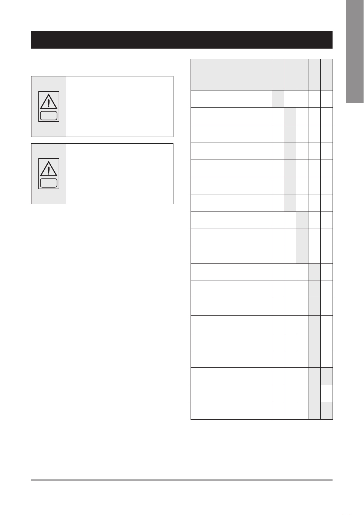
9 - Maintenance
Carefully read the “Safety” section of this manual before carrying
out any maintenance operations.
Do not discharge the refrigerant into the
atmosphere while the refrigeration circuits
are being drained. Use appropriate recovery
equipment.
DANGER
DANGER
Unless otherwise specified, the operations described below may be
carried out only by a trained maintenance operator.
When the recovered refrigerant cannot be reused, return it to the manufacturer.
Do not throw away the waste oil of the
compressor, because it contains refrigerant in
solution.
The waste oil must be returned to the
manufacturer.
9.1 General requirements
Units have been designed for continuous operation, providing
that they are subjected to regular maintenance, within the limits
specified in this manual. Each unit must be serviced according to the
programme by the User/Customer, and must be inspected at regular
intervals by the personnel of one authorised Service Centers.
It is the responsibility of the User to meet these maintenance
requirements and/or to enter into an agreement with one of authorised
Service Centers, so as to properly safeguard the operation of the
appliance.
During the warranty period, in case of damage or failures caused
by improper maintenance, manufacturer will not refund the costs
incurred to repair the appliance in its original state.
The provisions of this section apply only to standard units; according
to the order requirements, other documentation may be added,
concerning any modifications or supplementary accessories.
9.2 Planned maintenance
Maintenance inspections must be carried out according to the
program below, by a qualified person.
As a general rule, units cannot be repaired directly by the user, who
shall not try to service or repair any failures or anomalies identified
during daily inspections. If you are in doubt, please contact authorised
Service Centre.
Operations
Check the temperature
of the leaving fluid
Check the pressure drops
in the heat exchanger
Check for electric absorption
Check suction pressure
and temperature
Check delivery pressure
and temperature
Check the oil level in the compressor
Check that there are no gas bubbles
in the liquid line
Check that the fins of
the external coil are clean (if any)
Check the operation of the oil heaters
Check the remote control switches
Check the operation
of the LP pressure switch
Check the operation
of the HP pressure switch
Check the insulation of
the heat exchanger
Check that terminals are tightened
Check that the terminals’
screws are tightened
Clean the exterior of the unit
with water and soap
Check the density
of the antifreeze (if any)
Check the operation
of the flow switches
Check the operation
of the solenoid valve
•
Daily
•
•
•
•
•
•
Weekly
•
•
•
Monthly
Beginning
•
•
•
•
•
•
• •
•
• •
End of
season
of season
English
75
Page 77

9 - Maintenance (continued)
9.3 Refrigerant charge
Do not inject refrigerant liquid into the LP side
of the circuit. Be very careful, and charge the
circuit properly.
If the charge is insufficient, the efficiency of
the unit will be lower than expected. In the
worst of cases the LP pressure switch may be
activated, resulting in the halting of the unit.
WARNING
WARNING
Fill the refrigeration circuit after it has been drained for maintenance
purposes (leaks, replacement of the compressor etc.). The amount
of the charge is indicated on the plate affixed to the unit.
Before refilling, it is important to drain and de-hydrate the circuit, thus
obtaining a minimum abs. pressure value of 0.06 mbar.
Inject the refrigerant fluid before removing the vacuum, then fill the
circuit up to 90% of the total gas requirement (in liquid form). The
appliance must be filled through the filling valve on the liquid line, on
the outlet side of the condenser.
In the presence of an excess charge,
the condensing pressure will rise (in the
worst of cases, the HP pressure switch
may be activated, resulting in the stop of
the equipment), and the consumption will
increase as well.
It is strictly forbidden to use the compressor
as a vacuum pump to drain the plant.
Compressors use polyester oil. During
maintenance operations on the compressor,
or if you have to open the refrigerant circuit
in any point, remember that this type of oil
is highly hygroscopic, and accordingly it is
WARNING
important that it is not left exposed to the
weather for prolonged periods, as this would
require the replacement of the oil.
Before opening the panel, the unit must stay
switched off for at least 5 minutes
WARNING
9.5 Condenser
Condenser coils are of microchannel type made of 100% aluminium
(fins and tubes). In the presence of leaks caused by any damage
or shock, the coils shall be repaired or replaced by one authorised
Service Center. To ensure the effective and correct operation of the
condenser coils, it is important to keep the condenser’s surface
perfectly clean, and to check that there is no foreign matter, such
as leafs, wires, insects, waste etc. If the coil becomes dirty, there
is an increase in the absorption of electric energy. Furthermore, the
maximum pressure alarm may be activated and may halt the unit.
The condenser must be cleaned with a LP compressed air jet, parallel
to the aluminium fins, in the direction opposite to the air circulation.
To clean the coil a vacuum cleaner, or a jet of water and soap can
also be used.
It is recommended to connect the refrigerant cylinder to the filling
valve on the liquid line, and to arrange it in such a way as to inject
only liquid refrigerant.
Then start the compressor and let the gas flow from the cylinder, up
until the liquid flow, which can be observed through the sight glass,
is limpid.
9.4 Compressor
Compressors are delivered with the necessary charge of lubricating
oil. During normal operation, this charge is sufficient for the whole
life of the unit, providing that the efficiency of the refrigeration circuit
is satisfactory and if it has not been overhauled.
If the compressor needs to be replaced (following a mechanical
failure or if burnt), contact one of manufacturer.
Hazardous voltages in frequency inverter
housing!
Any contact will cause severe injury or death.
Never open FI housing during operation.
In case of any operation in the FI housing,
switch off the main switch and secure it
WARNING
against being switched on again.
Wait for at least 5 minutes until all capacitors
have been discharged. Close perfectly the FI
housing before switching on again.
Be careful not to damage the aluminium fins
during cleaning.
WARNING
Standard microchannel condenser coils are made of aluminium
without coating, that is relatively corrosion resistant and suitable for
installations in areas without corrosive agents.
In case of installation in environments with high level of pollutants,
salts or other atmospheric agents that could shorten the life of heat
exchangers, it is recommended to select a proper anticorrosion
treatment protecting the overall coil.
Before the unit is installed, make sure that the
coil configuration is compliant to Systemair
Coil Policy. For additional information, please
WARNING
contact Systemair Service.
76
Page 78

9 - Maintenance (continued)
9.6 Fans
The fans of the condenser, of axial type, are complete with impeller
with aerodynamic profile blades and a cylindrical nozzle. The motor’s
bearings are lubricated forever.
Before starting the appliance, after any maintenance operations
involving the disconnection of 3-phase connections, check that the
direction of rotation of the fans is the one indicated by the arrow
(upward air current). If the direction of rotation is wrong, invert two
of the three supply phases to the motor.
9.7 Dehydrating filter
The refrigeration circuits are provided with dehydrating filters.
The filter clogging is marked by the presence of air bubbles in the
sight glass, or by the difference between the temperatures measured
downstream from and upstream of the drying filter. If, once the
cartridge has been replaced, there are still some air bubbles, the
appliance has lost a part of the refrigerant charge in one or more
points, that must be identified and serviced. In any case it is
suggested the good practice to replace the filter cartridges at each
maintenance interventions in order to keep the refrigerant circuit in
full efficiency.
9.8 Sight glass
9.9 Electronic expansion valve
The circuit of the unit is equipped with electronic expansion valve.
The valve is calibrated for an overheating of 6 °C.
Procedure to check for overheating:
– Measure the suction pressure with the pressure gauges on the
board of the unit o using a pressure gauge connected to the
service valve on the suction side.
– From the pressure gauge’s temperature scale, measure the
saturated suction temperature (Tsa) which corresponds to the
pressure value.
– Using a contact pressure gauge affixed to the outlet fitting of the
gas of the evaporator, measure the actual temperature (Tse).
Overheating calculation (S):
S = Tse - Tsa
Overheating is regulated through the expansion valve.
If the electronic expansion valve cannot be regulated, it is probably
broken, and shall be replaced. The replacement must be carried out
by a Service Centre.
English
The sight glass is used for inspecting the refrigerant flow and the
humidity % of the refrigerant. The presence of bubbles indicates that
the dehydrating filter is clogged or the charge insufficient.
A colour indicator is positioned inside the sight glass. If you compare
the colour of the indicator to the scale on the ring of the sight glass,
you can calculate the percentage of humidity of the refrigerant. If it
is excessive, replace the filter’s cartridge, operate the appliance for
1 day and then check the humidity % again. When the humidity % is
within the pre-determined range, no other operations are required. If
the humidity % is still too high, replace the dehydrating filter again,
start the unit and operate it for another day.
9.10 Evaporator
Check at regular intervals that the water side of the heat exchanger
is perfectly clean. To do this, measure the pressure drop, water side
(see Section 8) or measure the temperature of the liquid leaving
and entering the heat exchanger, and compare it to the evaporation
temperature.
To obtain an effective heat exchange, the difference between the
temperature of the leaving water and the saturated evaporating
temperature must be in the 2 - 4 °C range. A greater difference
would indicate a low efficiency of the heat exchanger (i.e. the heat
exchanger is dirty).
In this case, the heat exchanger must be subjected to chemical
cleaning, an operation that shall be carried out by authorised
engineers.
For other maintenance operations (extraordinary overhauling,
replacement of the heat exchanger etc.), contact an authorised
Service Centre.
77
Page 79

10 - Troubleshooting
The table below lists the anomalies of operation of the unit, the relevant causes and the corrective measures. For anomalies of any other type or
not listed, contact one of authorised Service Centre for technical assistance.
Anomaly Cause Operation
The unit continues
to work, but
without cooling
Ice on the suction
line
Excessive noise
Low oil level in the
compressor
One or both
compressors are
not working
Activation of the
LP alarm, stop of
the unit
Activation of the
HP alarm, stop of
the unit
The liquid line is
too hot
Frosting of the
liquid line
Compressor with
Frequency Inverter
(FI) not available
Insufficient charge of refrigerant. Refill.
The dehydrating filter is clogged. Replace.
Wrong calibration of overheating.
Vibration of lines. Check the clamping brackets, if any.
Whistler emitted by the thermostatic
expansion valve.
Noisy compressor.
One or more gas or oil leaks in the circuit. Identify and remove leaks.
Mechanical failure of the compressor. Request the intervention of a Service Centre.
Anomaly of the oil heater of the
compressor’s base.
Breaking of the electric circuit.
Intervention of the HP pressure switch.
The fuse of the control circuit is broken. Check for ground dispersions and shor t circuits. Replace fuses.
Loosened terminals. Check and tighten.
Halt caused by thermal overload of the
electric circuit.
Wrong wiring. Check wiring of check and safety devices.
The line voltage is too low.
Short-circuit of the compressor’s motor. Check the continuity of the winding.
Seized compressor. Replace the compressor.
Gas leak. Identify and remove the leak.
Insufficient charge. Refill.
Failure of the pressure switch. Replace the pressure switch.
Failure of the pressure switch. Check the operation of the pressure switch, replace it if defective.
The delivery valve is partially closed. Open the valve and replace it, if faulty.
Substances with condensable gases in the
circuit.
The fan of the condenser is stopped. Check cables and motor. If defective, repair or replace.
Insufficient charge. Identify and remove the cause of the loss of charge and refill.
The valve of the liquid line is partially closed. Check that valves are open.
The liquid filter is clogged. Replace the cartridge or the filter.
Communication between Fequency Inverter
(FI) and unit control board interrupted
The unit control board is defective Change of control board
The Frequency inverter is defective Change of Frequency Inverter
Increase overheating.
Check the charge.
Refill.
Check the dehydrating filter.
Seized bearings; replace the compressor.
Check that the compressor’s locknuts are tightened.
Check the electric circuit and the resistor of the heater of the motor base,
and replace defective components.
Check the electric circuit and detect any ground dispersions and short
circuits. Check fuses.
Reset the pressure switch and the control panel and restart the appliance.
Identify and remove the cause that enabled the pressure switch.
Check the operation of check and safety devices. Identify and remove the
cause.
Check voltage. If problems regard the system, solve them. If they are
caused by the distribution network, inform the Energy Distributor.
Drain the circuit.
Check that the data cable from unit control board to FI is not defective and
the connection is well tightened
Check that the FI power supply cables are not defective and the
connection is well tightened
Check that the main supply voltage is inside the permitted range of
application
Check that the control transformer for auxiliary supply is not defective and
the connection is well tightened
78
Page 80

10 - Troubleshooting (continued)
The table below lists anomalies of operation, causes and corrective measures, specifically related to pump inverter (optional).
English
S.NO.
1 W/A2 Live zero error
2 W/A7 DC over voltage
3 W/A8 DC under voltage
4 W/A9 Inverter overloaded
WARNING /
ALARM NO.
DESCRIPTION TROUBLESHOOTING
→ Check connections on all analog mains terminals.
→ Control card terminals 53 and 54 for signals, terminal 55 common
→ VLT® General Purpose I/O MCB 101 terminals 11 and 12 for signals, terminal 10
common
→ VLT® Analog I/O Option MCB 109 terminals 1, 3, and 5 for signals, terminals 2, 4, and
6 common.
→ Check that the frequency converter programming and switch settings to match the
analog signal type.
→ Perform an input terminal signal test.
→ Connect a brake resistor.
→ Extend the ramp time.
→ Change the ramp type.
→ Activate the functions in parameter 2-10 Brake Function.
→ Increase parameter 14-26 Trip Delay at Inverter Fault.
→ If the alarm/warning occurs during a power sag, use kinetic back-up (parameter 14-10
MainsFailure).
→ Check that the supply voltage matches the frequency converter voltage.
→ Perform an input voltage test.
→ Perform a soft charge circuit test.
→ Compare the output current shown on the LCP with the frequency converter rated
current.
→ Compare the output current shown on the LCPwith the measured motor current.
→ Show the thermal frequency converter load onthe LCP and monitor the value. When
running above the frequency converter continuous current rating, the counter increases.
When running below the frequency converter
continuous current rating, the counter decreases.
Check for motor overheating:
→ Check if the motor is mechanically overloaded.
→ Check that the motor current set in parameter 1-24 Motor Current is correct.
5 W/A10
6 W/A11
7 W/A12 Torque limit
8 W/A27
9 A4 Mains phase loss → Check the supply voltage and supply currents to the frequency converter.
10 A13 Over Current
Motor ETR over
temperature
Motor thermistor over
temperature
Brake chopper shortcircuited
→ Ensure that the motor data in parameters 1–20 to 1–25 are set correctly.
→ If an external fan is in use, check that it is selected in parameter 1-91 Motor External
Fan.
→ Running AMA in parameter 1-29 Automatic Motor Adaptation (AMA) tunes the frequency
converter to the motor more accurately and reduces
thermal loading
Check for motor overheating:
→ Check if the motor is mechanically overloaded.
→ When using terminal 53 or 54, check that the thermistor is connected correctly between
either terminal 53 or 54 (analog voltage input) and terminal 50 (+10 V supply). Also
check that the terminal switch for 53 or 54 is set for voltage. Check that parameter 1–93
Thermistor Source
selects terminal 53 or 54.
→ When using terminal 18, 19, 31, 32, or 33 (digital inputs), check that the thermistor is
connected correctly between the digital input terminal used (digital input PNP only) and
terminal 50. Select the terminal to use in parameter 1–93 Thermistor Source.
→ If the motor torque limit is exceeded during ramp-up, extend the ramp-up time.
→ If the generator torque limit is exceeded during ramp-down, extend the ramp-down time.
→ If torque limit occurs while running, increase the torque limit. Make sure that the system
can operate safely at a higher torque.
→ Check the application for excessive current draw on the motor.
→ Remove power to the frequency converter and remove the brake resistor.
→ Remove the power and check if the motor shaft can be turned.
→ Check that the motor size matches the frequency converter.
→ Check that the motor data is correct in parameters 1-20 to 1-25.
79
Page 81

10 - Troubleshooting (continued)
S.NO.
11 A14 Ground fault
12 A29 Drive over temperature
13 A30 Motor phase U missing
14 A31 Motor phase V missing → Remove the power from the frequency converter and check motor phase V.
15 A32 Motor phase W missing → Remove the power from the frequency converter and check motor phase W.
16 A47 24 V supply low → Check for a defective power card.
17 A65
WARNING /
ALARM NO.
DESCRIPTION TROUBLESHOOTING
Remove power to the frequency converter and repair the ground fault.
→ Check for ground faults in the motor by measuring the resistance to ground of the motor
cables and the motor with a megohmmeter.
→ Reset any potential individual offset in the 3 current transducers in . Perform the manual
initialisation or perform a complete AMA. This
method is most relevant after changing the power card.
Check for the following conditions.
→ The ambient temperature is too high.
→ The motor cables are too long.
→ Incorrect airflow clearance above and below the frequency converter.
→ Blocked airflow around the frequency conver ter.
→ Damaged heat sink fan.
→ Dirty heat sink.
→ Remove the power from the frequency converter and check motor phase U.
Control Board Overtemperature
→ Check that the ambient operating temperature is within the limits.
→ Check for clogged filters.
→ Check the fan operation.
→ Check the control card.
18 A244 Heatsink temp
19 A16 Shor t Circuit Remove the power to the frequency converter and repair the short circuit.
20 A33 Inrush fault → Let the unit cool to operating temperature
21 A38 Internal fault
22 A45 Ear th fault 2
23 A46 Pwr. card supply
24 A48 1.8 V supply low
25 A69 Pwr. Card Temp
→ Cycle power.
→ Check that the option is properly installed
→ Check for loose or missing wiring
→ Check for proper grounding and loose connections.
→ Check for proper wire size.
→ Check the motor cables for short circuits or leakage currents.
→ Check for a defective power card.
→ Check for a defective control card.
→ Check for a defective option card.
→ If a 24 V DC supply is used, verify proper supply power."
→ Check for a defective control card.
→ If an option card is present, check for overvoltage.
→ Check that the ambient operating temperature is within limits.
→ Check for clogged filters.
→ Check fan operation.
→ Check the power card.
80
Page 82

11 - Spare Parts
11.1 Spare part list
The table below shows the list of spare parts recommended during
the first two years of operation.
Component Number
HP pressure switch 1
LP pressure switch 1
Gas filter 2
Electronic expansion valve 2
Auxiliary relays 2
Fan’s fuses 6
Compressor’s fuses 6
Auxiliary fuses 6
Set of compressor contactors 1
Fan’s contactor 1
Water sensor 1
Air sensor 1
Electronic card 1
Keyboard 1
Compressor oil resistor 1
English
11.2 Oil for compressors
The compressors are lubricated with Ester oil BSE 170 (Viscosity of
170 St / 40 °C).
11.3 Wiring diagrams
The wiring diagrams are installed inside the doors of the electrical
panels of the unit. Any request for wiring diagrams shall be forwarded
to manufacturer’s Service Centre.
81
Page 83

12 - Dismantling, Demolition and Scrapping
During the draining of the refrigeration
circuits, do not let the refrigerant overflow in
the surrounding atmosphere.
DANGER
DANGER
For the disposal, contact the competent authority for information.
The circuit must be drained using suitable
recovery equipment.
Do not disperse the waste oil of the
compressors in the environment, since it
contains some dissolved refrigerant.
After draining operations, the piping of the hydraulic networks can be
disconnected and disassembled.
Once they have been disconnected as specified, the packaged units
can be disassembled in a single piece. First of all, disassemble
the anchoring screws and then lift the unit from the position of
installation, and hook it to the lifting points provided, using suitable
lifting equipment.
To this end, refer to Chapter 4 for the installation of these appliances,
to Chapter 8 for their weights and Chapter 3 for handling.
The units that, once disconnected, cannot be removed in a single
piece, must be dismantled on site; in this case, be very careful with
the weight and handling of every single component.
It is always advisable to dismantle the units following the installation
steps, but in reverse.
Unless otherwise specified, the maintenance operations listed below
may be carried out by any trained maintenance operator.
12.1 Generalities
Open each line that supplies the unit, including the ones of control
circuits. Make sure that all disconnecting switches are secured
in the off position. The power cables can be disconnected and
disassembled. Refer to Chapter 4 for the position of connection
points.
Remove all the refrigerant from the refrigeration circuits of the
unit and store it in suitable containers, using a recovery unit. If its
characteristics have remained the same, the refrigerant can be used
again. Contact the competent authority to obtain information about
disposal. In NO event shall the refrigerant be discharged into the
atmosphere. The oil in each refrigeration circuit must be drained and
collected into a suitable container; then it shall be disposes of in
conformity with local regulations that apply to the disposal of waste
lubricants. Any oil spillage must be recovered and disposed of in like
manner.
Isolate the unit’s heat exchangers from the external hydraulic circuits
and drain the heat exchange sections of the plant.
If no shutoff valves have been provided, it may
be necessary to drain the whole plant.
If a glycoled solution or a similar fluid has been
used in the hydraulic circuits, or if chemical
additives have been added to the circulating
water, the circulating fluid MUST be drained in
DANGER
a proper way.
For NO reason shall a circuit containing
glycoled water or a similar solution be
discharged directly into the drains or surface
waters.
Some residues of oil, glycoled water or similar
solutions may remain in certain parts of the
unit. These residues must be recovered and
DANGER
It is very important to ensure that, while a component of the unit is
being removed, all the others are properly supported.
DANGER
Once disassembled, the components of the unit can be disposed of
in conformity with current regulations.
disposed of according to the procedures
specified above.
Use only lifting means of adequate capacity.
12.2 RAEE Directive (only UE)
• The RAEE Directive requires that the disposal and
recycling of electrical and electronic equipment
must be handled through a special collection, in
appropriate centers, separate from that used for the
disposal of mixed urban waste.
• The user has the obligation not to dispose of the
equipment at the end of the useful life as municipal
waste, but to send it to a special collection center.
• The units covered by the RAEE Directive are marked
with the symbol shown above.
• The potential effects on the environment and human
health are detailed in this manual.
82
Page 84

Systemair srl
Via XXV Aprile, 29
20825 Barlassina (MB)
Italy
Tel. +39 0362 680 1
Fax +39 0362 680 693
www.systemair.com
As part of our ongoing product improvement programme, our products
are subject to change without prior notice. Non contractual photos.
Dans un souci d’amélioration constante, nos produits peuvent être
modifiés sans préavis. Photos non contractuelles.
In dem Bemühen um ständige Verbesserung können unsere Erzeugnisse
ohne vorherige Ankündigung geändert werden. Fotos nicht vertraglich
bindend.
A causa della politica di continua miglioria posta in atto dal costruttore,
questi prodotti sono soggetti a modifiche senza alcun obbligo di preavviso.
Le foto pubblicate non danno luogo ad alcun vincolo contrattuale.
Con objeto de mejorar constantemente, nuestros productos pueden ser
modificados sin previo aviso. Fotos no contractuales.
 Loading...