

Page 1
Topvex SR/TR03, SR/TR04, SR/TR06
Compact Air Handling Unit
Installation instructions
Document in original language | 151617 · A003
GB
Page 2

© Copyright Systemair AB
All rights reserved
E&OE
Systemair AB reserves the rights to alter their products without notice.
This also applies to products already ordered, as long as it does not affect the previously agreed specifications.
151617 | A003
Page 3

1 EU Declaration of Conformity . .. ..... ..... .... .... .... . ...1
2 Warnings. ..... .... .... . .... .... .... . .... .... .... ..... .... .... . .2
3 Product information ... . .... .... .... . .... .... .... . .... .... ...2
3.1 General... .... .... . .... .... .... . ... . .... .... ..... .... ..2
3.2 Technical data .... . ... . .... .... ..... .... .... . .... .... 3
3.2.1 Dimensions and weights
Topvex SR 03-06 .... .... .... . .... .... ..3
3.2.2 Space required Topvex SR 03-
06... ..... .... .... . .... .... .... . .... .... .... .4
3.2.3 Dimension and weight Topvex
TR 03-06... . .... .... .... ..... .... .... . .... 5
3.2.4 Space required Topvex TR 03-
06... ..... .... .... . .... .... .... . .... .... .... .7
3.2.5 Electrical data Topvex SR/TR
03-06.. .... . .... .... .... . .... .... .... . .... .7
3.3 Transport and storage . ..... .... .... ..... .... .... ..8
4 Installation.. .... ..... .... .... . .... .... .... . .... .... .... ..... ...9
4.1 Unpacking ... . .... .... ..... .... .... . ... . .... .... .... . .9
4.2 Where/how to install .... . ... . .... .... .... . .... .... 9
4.3 Installing the unit. .... .... .... . .... .... ..... .... ... 10
4.3.1 Installation procedure... .... .... . .... 11
4.4 Supply air sensor... .... .... . .... .... .... . .... .... . 11
4.5 Connections .... . ... . .... .... ..... .... .... . .... .... . 12
4.5.1 Ducting ... .... . .... .... .... . .... .... ..... 12
4.5.2 Condensation and heat
insulation .... ..... .... .... . ... . .... .... . 13
4.5.3 Silencers ... . .... .... ..... .... .... . ... . .. 13
4.5.4 Electrical connections,
components. . .... .... .... . .... .... .... . 13
4.5.5 External connections . .... .... .... . ... 15
4.5.6 BMS Connection.. .... .... . .... .... .... 16
4.6 Installing NaviPad control panel .... . .... .... .. 17
4.6.1 Dimensions NaviPad .... .... . .... .... 17
4.6.2 Mount NaviPad . .... .... . .... .... .... . . 17
4.7 Additional equipment . .... . .... .... .... . .... .... . 17
Contents
151617 | A003
Page 4

Page 5
1 EU Declaration of Conformity
EU Declaration of Conformity |
1
Manufacturer
Systemair Sverige AB
Industrivägen 3
SE-739 30 Skinnskatteberg Sweden
Phone: +46 222 440 00
www.systemair.com
The manufacturer hereby confirms that Topvex SR/TR
03-06 comply with all applicable requirements in the following directives and regulations.
Machinery Directive 2006/42/EC
Ecodesign Directive 2009/125/EC
327/2011 Requirements for fans
1253/2014 Requirements for ventilation units
Low Voltage Directive 2014/35/EU
EMC Directive 2014/30/EU
RoHS Directive 2011/65/EU, 2015/863/EU
The following harmonized standards are applied in applicable parts:
EN ISO 12100
Safety of machinery - General principles for design - Risk
assessment and risk reduction.
EN 62233
Measurement methods for electromagnetic fields of
household appliances and similar apparatus with regard
to human exposure.
EN 61000-6-2
Electromagnetic compatibility (EMC) – Part 6-2: Generic
standards – Immunity for industrial environments.
EN 61000-6-3
Electromagnetic compatibility (EMC) – Part 6-3: Generic
standards – Emission standards for residential, commercial and light-industrial environments.
EN 13053
Ventilation for buildings – Air handling units – Rating and
performance for units, components and sections.
The declaration applies only to product in the condition it
was delivered in and installed in the facility in accordance
with the included installation instructions. The insurance
does not cover components that are added or actions
carried out subsequently on the product.
The complete technical documentation is available.
Skinnskatteberg, 2020–08–04
EN 13857
Safety of machinery – Safety distances to prevent hazard
zones being reached by upper or lower limbs.
EN 60204-1
Safety of machinery – Electrical equipment of machines –
Part 1: General requirements.
EN 60335-1
Household and similar electrical appliances – Safety Part
1: General requirements.
EN 60335-2-40
Safety of household and similar electrical appliances Part 2-40: Particular requirements for electrical heat
pumps, air-conditioners and dehumidifiers.
EN 50106
Safety of household and similar appliances – Particular
rules for routine tests referring to appliances under the
scope of EN 60 335-1.
EN 60529
Degrees of protection provided by enclosures (IP Code).
Sofia Rask
Managing Director
151617 | A003
Page 6
Warnings
|
2
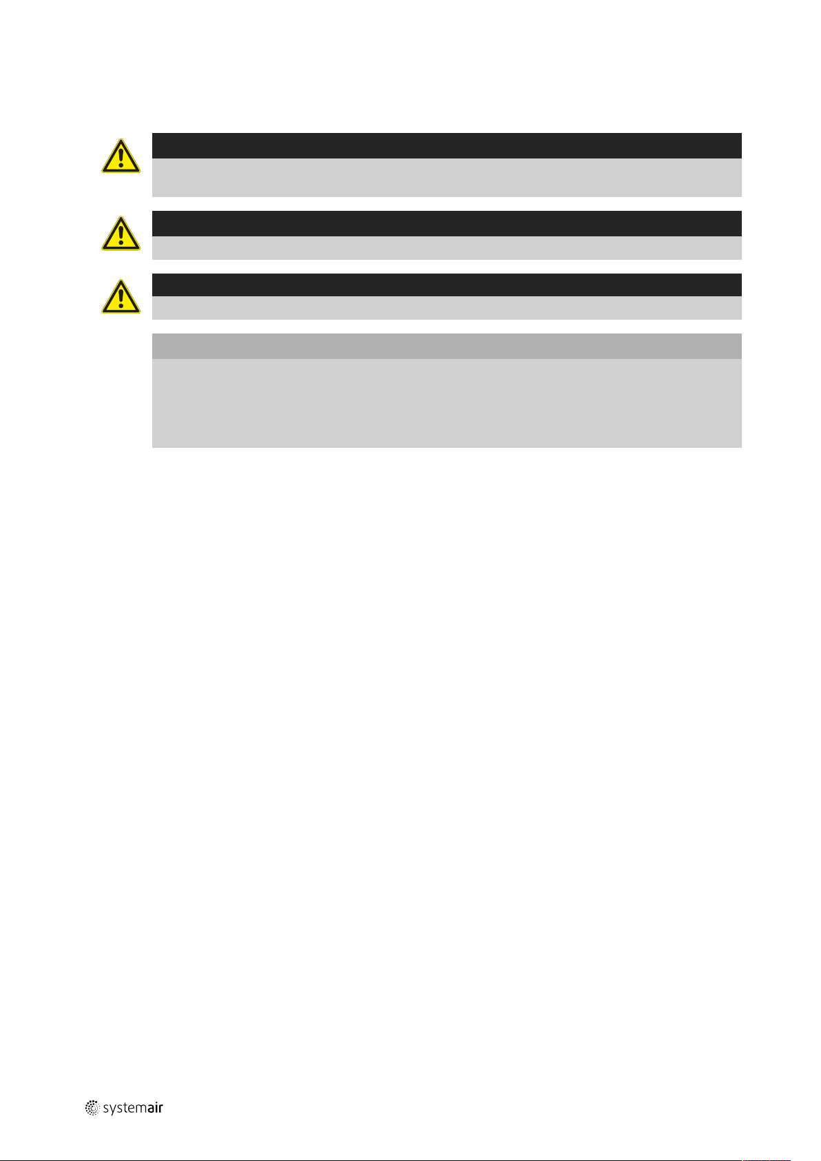
2 Warnings
The following admonitions will be presented in the different sections of the document:
Danger
• Indicates a potentially or imminently hazardous situation which, if not avoided, could result in death or
serious injury.
Warning
• Indicates a potentially hazardous situation that may result in minor or moderate injuries.
Caution
• Indicates a risk of damaging the product or prevent optimal operation.
Important
• This appliance can be used by children aged from 8 years and above and persons with reduced physical,
sensory or mental capabilities or lack of experience and knowledge if they have been given supervision
or instruction concerning use of the appliance in a safe way and understand the hazards involved.
• Children shall not play with the appliance. Cleaning and user maintenance shall not be made by children
without supervision.
3 Product information
3.1 General
This installation manual concerns air handling unit type Topvex SR/TR 03-06 manufactured by Systemair AB. Topvex
SR/TR 03-06 include the following model options:
• Model: SR03, SR04, SR06, TR03, TR04, TR06
• Heating coil: EL (Electric), HWL (Water coil, low power), HWH (Water coil, high power) or None.
• Right or left models: R (Right) L (Left). The side where the supply air is located when viewed from the access side.
• Airflow control: CAV – Constant Air Volume, VAV – Variable Air Volume = Constant duct pressure control (as an
accessory)
• M0: Aluminium fan impeller
This manual consists of basic information and recommendations concerning the design, installation, start-up and operation, to ensure a proper fail-free operation of the unit.
The key to proper and safe operating of the unit is to read this manual thoroughly, use the unit according to given
guidelines and follow all safety requirements.
151617 | A003
Page 7
3.2 Technical data
15R ½"
112
62
F
F
G
106
K
111
c/c E
C
100
H
I
J
I
H
B
30
c/c D
A
30
15R ½"
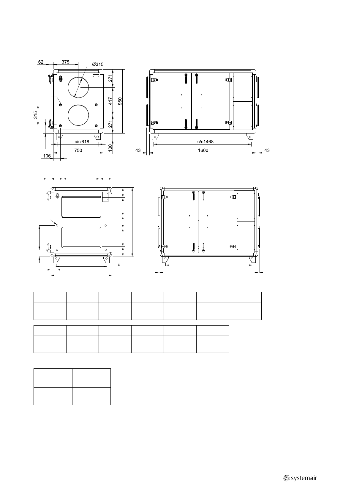
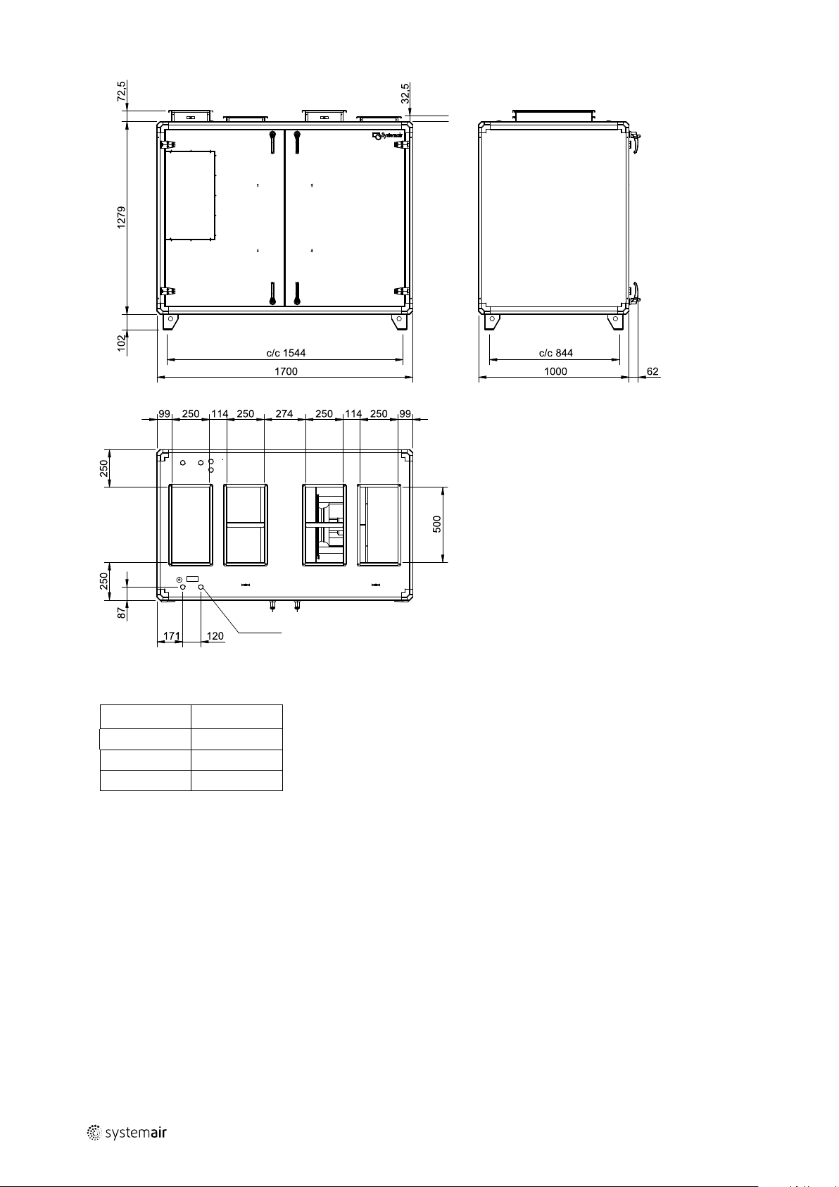
3.2.1 Dimensions and weights Topvex SR 03-06
Fig. 1 Dimensions (mm) SR03 (Drawn as a right hand unit)
Product information |
3
Fig. 2 Dimensions (mm) SR04, SR06 (Drawn as a right hand unit)
Model
A B C
SR04 1600 1041 850 1315 565 175
SR06 1600 1128 1000 1468 868 200
Model
G H I
SR04 500 171 250 200 355
SR06 600 164 300 200 396
Table 1 Weights Topvex SR 03-06
Model
Weight (kg)
SR03 220
SR04 270
SR06 300
c/c D c/c E
J
K
F
151617 | A003
Page 8
| Product information
M
N
4
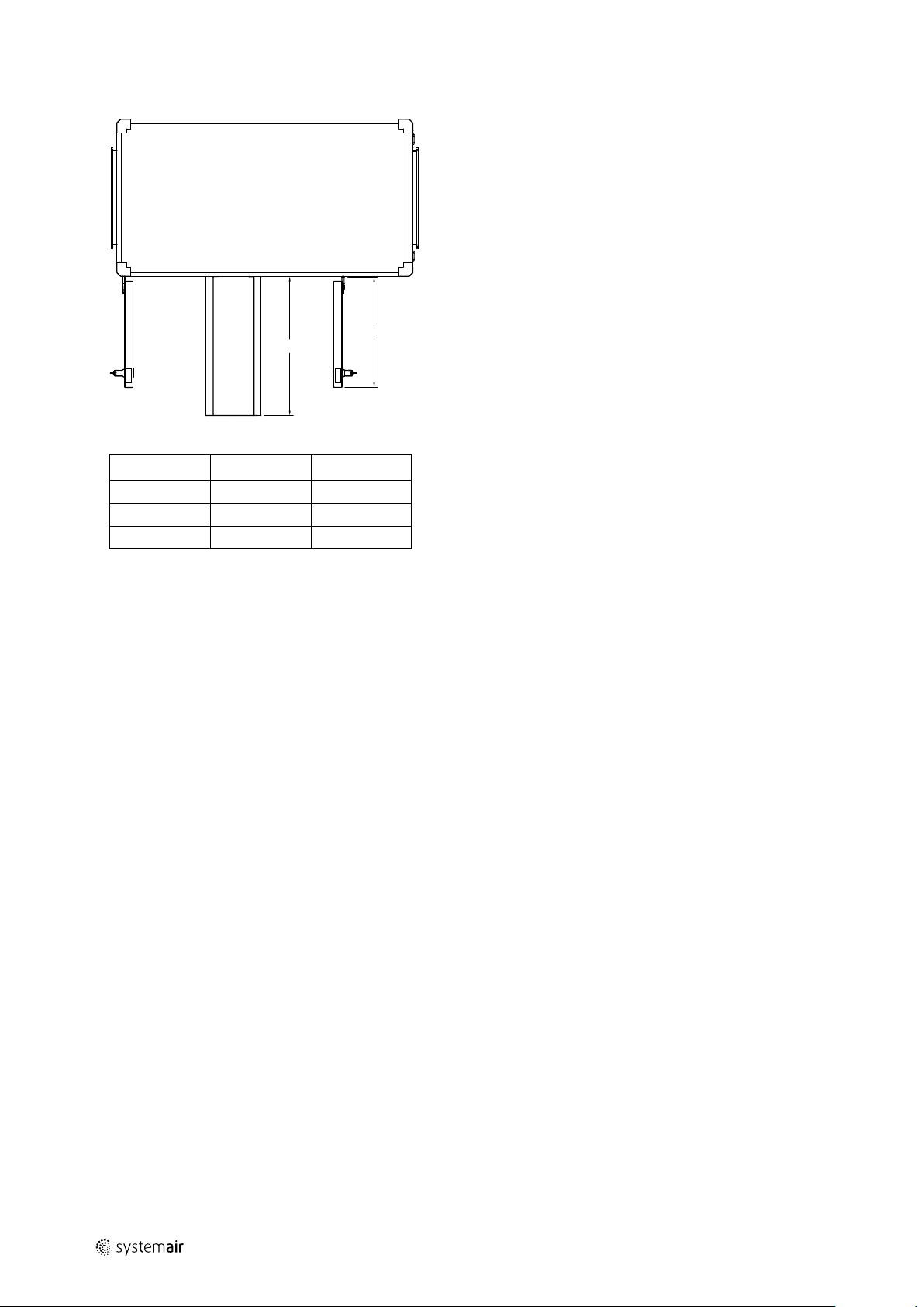
3.2.2 Space required Topvex SR 03-06
Fig. 3 Space required
Model
M (mm) N (mm)
SR03 650 603
SR04 750 603
SR06 900 603
151617 | A003
Page 9

3.2.3 Dimension and weight Topvex TR 03-06
Product information |
5
Fig. 4 Dimensions (mm) TR03, TR04 (Drawn as a left hand unit)
Model
TR03 1180 1230 750 1048 618 193
TR04 1480 1280 850 1348 718 209
Model
TR03 265 195 260 295 127 250
TR04 354 315 220 315 163 315
A B C
G H I
c/c D c/c E
J
K
F
øL
151617 | A003
Page 10
| Product information
15R(½")
6
Fig. 5 Dimensions (mm) TR06
Table 2 Weights Topvex TR 03-06
Model Weight
TR03 230
TR04 290
TR06 360
151617 | A003
Page 11
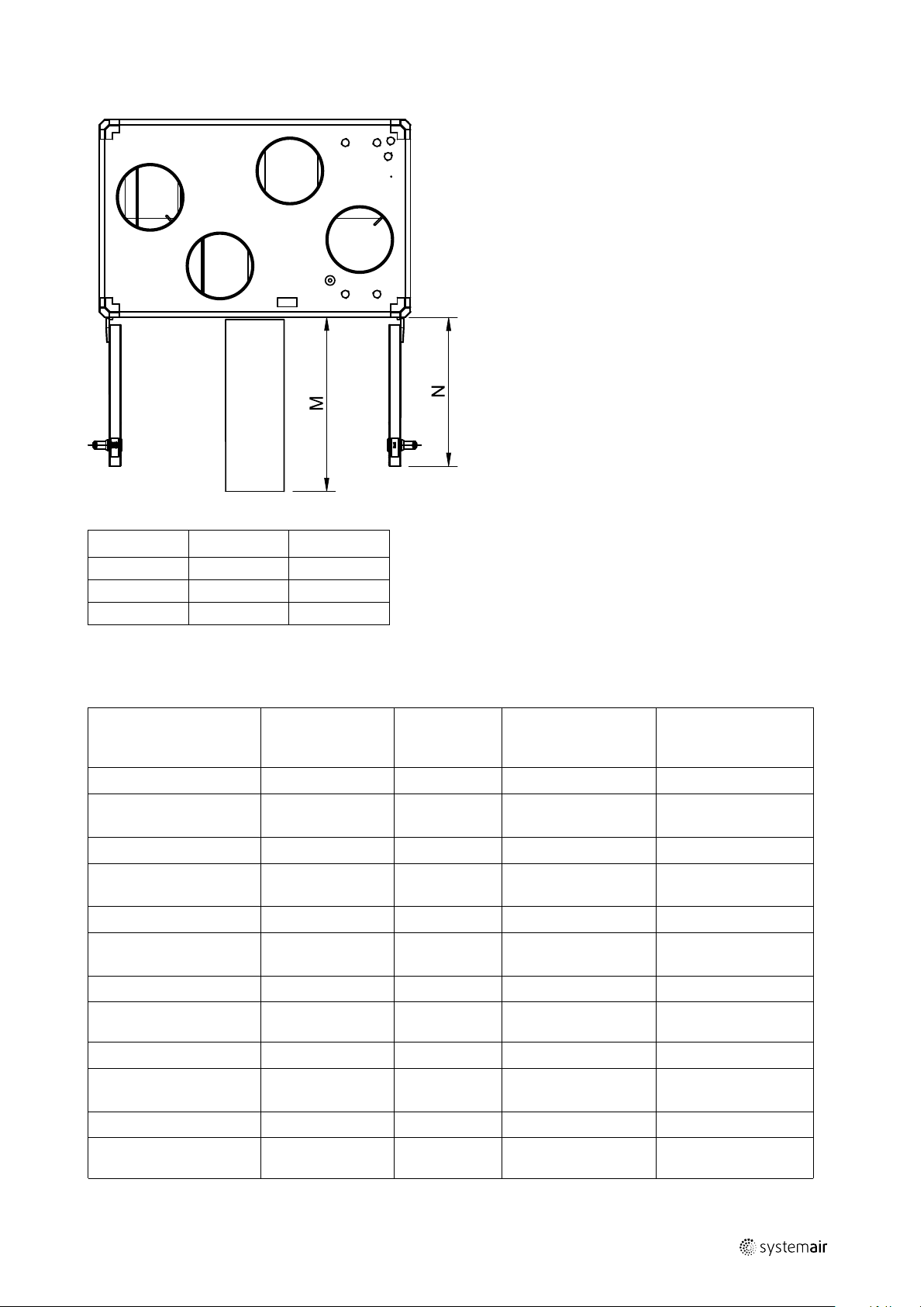
3.2.4 Space required Topvex TR 03-06
Product information |
7
Fig. 6
Model
TR03 660 570
TR04 760 715
TR06 910 825
M (mm) N (mm)
3.2.5 Electrical data Topvex SR/TR 03-06
Table 3 Power Consumption
El Heating
battery (kW
tot.)
–
–
–
Model
SR/TR03 EL
SR/TR03 (None, HWL/
HWH)
SR/TR03 El M0
SR/TR03 (None, HWH
M0)
SR/TR04 EL
SR/TR04 (None, HWL/
HWH)
Fans (W tot.) 230V
1~ and 400 V 3N~
1412 3 3x13 3x16
1412
1014 3 3x13 3x16
1016
1460 4 3x16 3x20
1460
Fuse (mains) (A) for
230V 1~ and 400 V
3N~
10 10
13 13
10 10
Fuse (mains) (A) for
230V 1~ and 230V 3~
SR/TR04 El M0
SR/TR04 (None, HWH)
M0
SR/TR06 EL
SR/TR06 (None, HWL/
HWH)
SR/TR06 El M0
SR/TR06 (None, HWH)
M0
151617 | A003
1560 4 3x16 3x20
1560
1794 6.3 3x16 3x25
1794
2066 6.3 3x16 3x25
2066
–
–
–
10 13
3x10 3x10
3x10 3x13
Page 12

| Product information
8
3.3 Transport and storage
The Topvex SR/TR 03-06 should be stored and transported in such a way that it is protected against physical damage
that can harm panels, handles, display etc. It should be covered so that dust, rain and snow cannot enter and damage
the unit and its components. The appliance is delivered in one piece containing all necessary components, wrapped in
plastic on a pallet for easy transportation.
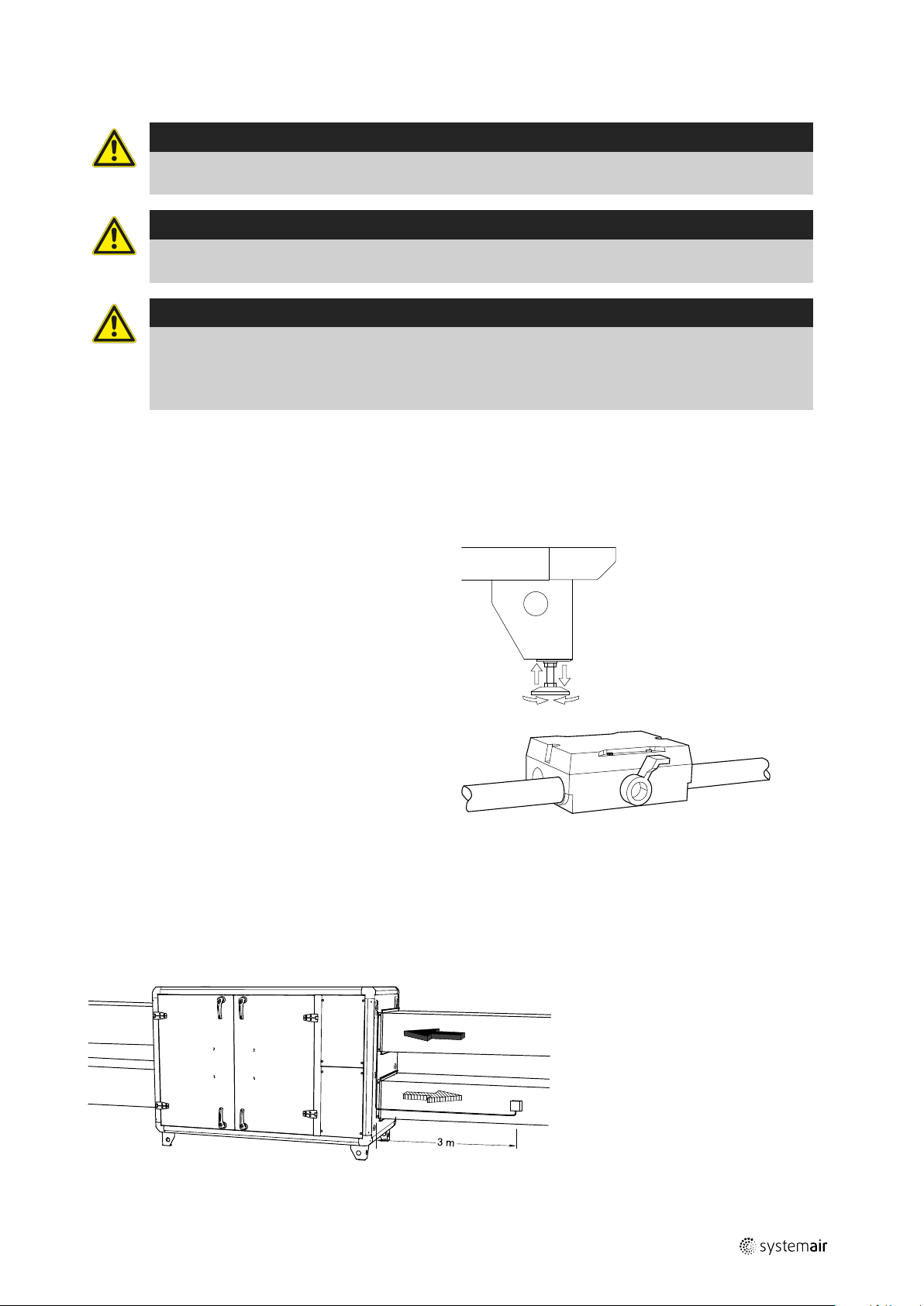
When transporting the Topvex SR/TR 03-06 units, use a forklift placed on the gable of the unit (figure 7.)
Warning
The unit is heavy. Be careful during transport and mounting. Risk of injury through pinching. Use protective
clothing.
Fig. 7 Transporting the unit
151617 | A003
Page 13

Installation |
4 Installation
4.1 Unpacking
Verify that all ordered equipment are delivered before starting the installation. Any deviation from the ordered equipment must be reported to the supplier of Systemair products.
4.2 Where/how to install
Place the unit on a horizontal flat surface. It’s important that the unit is completely levelled before it is put into
operation.
Place the unit preferably in a separate room (e.g. storage, laundry room, attic or similar).
Topvex SR/TR 03-06 can be installed outside if weather protected. An outdoor air section, ODS is available as
accessory.
If the unit is installed in a cold place it is important that the unit is not shut-off by the main switch. As long as the main
voltage is on the electrical cabinet will be kept warm also in cold climates.
When choosing the location it should be kept in mind that the unit requires maintenance regularly and that the inspection doors should be easily accessible. Leave free space for opening the doors and for taking out the main components
(figure 3 and figure 6).
Avoid placing the appliance against a wall, as low frequency noise can cause vibrations in the wall even if the fan
noise-level is acceptable. If this is not possible it is recommended to carefully insulate the wall.
9
The outdoor air intake of the building should if possible be put in the northern or eastern side of the building and away
from other exhaust outlets like kitchen fan outcasts or laundry room outlets.
151617 | A003
Page 14

| Installation
10
4.3 Installing the unit
The unit must be installed in the following position (figure 8 and figure 9).
Fig. 8 Installation position (left hand unit)
Fig. 9 Installation position (right hand unit)
Table 4 Symbol description
Symbol Description
Supply air
Exhaust air
Outdoor air
Extract air
151617 | A003
Page 15
4.3.1 Installation procedure
Warning
Beware of sharp edges during mounting and maintenance. Make sure that a proper lifting device is used.
Use protective clothing.
Warning
The units electrical connection to the mains power supply must be preceded by an all pole circuit breaker
with a minimum 3 mm gap.
Danger
• Make sure that the mains power supply to the unit is disconnected before performing any maintenance
or electrical work!
• All electrical connections must be carried out by an authorized installer and in accordance with local rules
and regulations.
1 Prepare the surface where the unit is to be mounted.
Make sure that the surface is flat, levelled and that it
supports the weight of the unit. Perform the installation in accordance with local rules and regulations.
Installation |
11
2 Lift the unit in place.
3 Level the unit with help of the enclosed mounting
feet
4 Connect the unit electrically to the mains power sup-
ply through the all pole circuit breaker, safety switch
(accessory). For Topvex SR 03-06 the wiring is led
through the gable of the unit. For Topvex TR 03-06
the wiring is led through the top of the unit casing. In
both cases the wiring is led directly to the electrical
connection box.
See enclosed wiring diagram, and (chapter 4.5.5) for
more information.
4.4 Supply air sensor
The supply air sensor is enclosed in the unit package on delivery. Mount the supply air sensor in the supply air duct after
the air handling unit (figure 10). See chapter 4.5.5 to which terminals the sensor needs to be connected in the electrical
connection box. Other temperature sensors are built in to the unit from factory.
Fig. 10 Installed supply air sensor (right hand connected unit)
151617 | A003
Page 16

| Installation
12
4.5 Connections
4.5.1 Ducting
Fig. 11 Connections and basic components (SR06 right hand unit, TR06 left hand unit)
Position Description
A
B
C
D Connection extract air
1
2 Fan extract air
3
4
5
6 Rotor motor
7
8
Connection supply air
Connection exhaust air
Connection outdoor air
Fan supply air
Filter supply air
Filter extract air
Heat exchanger
Electrical connection box
Re-heater battery
Symbol
151617 | A003
Page 17

Installation |
4.5.2 Condensation and heat insulation
Outdoor air duct and exhaust ducts must always be well insulated against condensation. Correct insulation installation
on ducts connected to the unit is especially important. All ducts installed in cold rooms/areas must be well insulated.
Use insulating covering (minimum 100 mm mineral wool) with plastic diffusion barrier. In areas with extremely low outdoor temperatures during the winter, additional insulation must be installed. Total insulation thickness must be at least
150 mm.
Caution
• If the unit is installed in a cold place make sure that all joints are covered with insulation, and tape well
• Duct connections/duct ends should be covered during storage and installation
• Do not connect tumble dryers to the ventilation system
4.5.3 Silencers
To avoid fan noise being transferred via the duct system, silencers should be installed both on supply and extract air.
To avoid noise being transferred between rooms via the duct system and also to reduce noise from the duct system itself, installation of silencers before every inlet diffuser is recommended.
4.5.4 Electrical connections, components
All electric connections are made in the electrical connection box which can be found in the front of the unit (figure 12).
The hatch is removed by unscrewing four screws (figure 12).
13
The unit must not be put into operation before all the electrical safety precautions have been read and understood. See
the enclosed wiring diagram for internal and external wiring.
All external connections to possible accessories are made to terminals inside the electrical connection box (table 4.5.5).
Fig. 12 Opening the electrical connection box
Danger
• Make sure that the mains power supply to the unit is disconnected before performing any maintenance
or electrical work!
• All electrical connections must be carried out by an authorized installer and in accordance with local rules
and regulations.
Topvex SR/TR 03-06 are equipped with a built in regulator and internal wiring (figure 13).
The figure shows the electrical connection box for the Topvex TR 03-06 units. The connection box for the Topvex SR
03-06 has the same layout and components with the difference that the electrical heater is situated in a separate
compartment.
151617 | A003
Page 18
| Installation
14
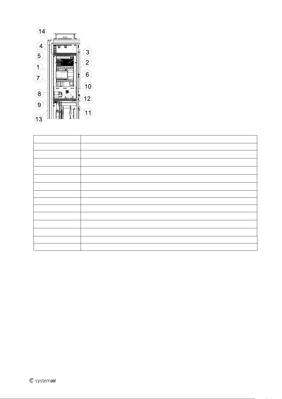
Fig. 13 Electric components
Position
1
2
3
4
5
6
7
8
9
10
11
12
13
14
Description
Control unit CU283W-4
Transformer 230/24V AC
Terminals for internal and external components
Terminals for internal wiring
Terminals for mains supply to the unit
Contactor (K2) Pump control water (HW units only, not present in EL-units)
Automatic fuse
Electric heater frame
Automatic fuse for heater
Contactor (K3) for control of EL heater
Thermostat (EL units)
Manual over heat protection reset (EL units)
Switch module
Panel outlet
151617 | A003
Page 19

4.5.5 External connections
Table 5 Connections to external functions
Terminal block
PE
N N
L1 L1
L2 L2
L3 L3
1 G
2 G0
10
12
1
DO ref DO reference
DO 2
WP L1
1
14
15
16
17
30
1
1
1
DO 4
DO 5
DO 6
DO 7
AI Ref Supply air temperature sensor reference neutral
31 AI 1
40
2
41
2
42
44
3
4
P1:50/P2:60
P:151/P2:61
P1:52/P2:62
3
74
3
75
76
3
90
Agnd UI reference neutral
UAI 1/(UDI 1)
UAI 2/(UDI 2)
UAI 3/(UDI 3)
DI ref Extended running/Fire alarm reference
B
A
N
DI 4
DI 5
DI 6
Agnd AO Reference neutral
93 AO 3
94 AO 4
1
Maximum current load for all DO combined: 8A
2
Connection to external pressure sensor in case of pressure controlled unit (VAV)
3
These inputs may only be wired to voltage free contacts
Description
Ground
Earthed neutral (mains power supply)
Phase (mains power supply)
Phase (mains power supply) 400V 3~/230V 3~
Phase (mains power supply) 400V 3~/230V 3~
Auxiliary supply (Pressure transmitter. Water
valve actuators)
Reference (Water valve actuator mains)
Outdoor/Exhaust air damper
Circulation pump hot water system
Cooling pump
DX Cooling step 1
DX Cooling step 2
Alarm output for DO signals
Temperature sensor, supply air
Pressure transmitter extract air
Pressure transmitter supply air
Frost protection sensor water heating
battery
Exo-line B Modbus, Exo-line connection
Exo-line A Modbus, Exo-line connection
Exo-line N Modbus, Exo-line connection
Extended running Normally open contact
Fire alarm Normally open contact
External stop Normally open contact
Control signal valve actuator, Water Heating
Control signal valve actuator, Cooling
Installation |
Remark
Used for phase 230V 1~ and
400V 3~
Used for phase 230V 1~ if the
unit has this mains
400V 3~/230V 3~
24V AC
24V AC
G (24V AC)
24V AC
Max. 2,0 A continuous load
230V AC
24V AC
24V AC
24V AC
24V AC
Use terminal 40 as reference
+ 24V DC
Use terminal 4 as reference
Use terminal 4 as reference
Use terminal 4 as reference
0–10V DC
0–10V DC
15
151617 | A003
Page 20

| Installation
16
4.5.6 BMS Connection
Communication possibilities for control unit.
• RS485(Modbus): 50-51-52 or 60-61-62
• RS485(BACnet): 50-51-52 or 60-61-62
• RS485(Exoline): 50-51-52-53 or 60-61-62-63
• TCP/IP Exoline
• TCP/IP Modbus
• TCP/IP WEB
• TCP/IP BACnet
RS 485 connection
Fig. 14
TCP/IP connection
Connect the device to panel outlet or switch module, depending on type of air handling unit.
Fig. 15 Panel outlet view is an example,
Note:
24V HMI connection dedicated for the display. The connection is only for HMI and no other
connections is permitted.
151617 | A003
Page 21

Installation |
4.6 Installing NaviPad control panel
The protection class of the NaviPad control panel is IP 54 and 0-50° permitted ambient temperature. If NaviPad is
mounted outdoor the panel needs to be protected against direct UV radiation. Communication between the panel and
the controller in the cabinet is possible with up to 100 meters of cable.
4.6.1 Dimensions NaviPad
NaviPad is the control panel for Systemair's air handling units and contains several selectable languages.
17
A B C
153 221 40,3 59,4 77,5 3,2
c/cD
E F
4.6.2 Mount NaviPad
The NaviPad control panel with 3 m cable, holder and screws are enclosed with the air handling unit. The air handling
units has pre-drilled holes in the doors. Mount the control panel holder on the air handling unit and place NaviPad in the
holder. NaviPad is connected to the panel outlet (pos 1) in the air handling unit at delivery.
See enclosed Quick guide for operating of the control panel.
4.7 Additional equipment
For information concerning additional external equipment such as valve actuators, motorized dampers, roof units, wall
grilles etc. see technical catalogue and their enclosed instructions.
For electrical connections of external components see enclosed wiring chart.
151617 | A003
Page 22

Systemair Sverige AB
Industrivägen 3
SE-739 30 Skinnskatteberg, Sweden
Phone +46 222 440 00
www.systemair.com
Topvex SR/TR03, SR/TR04, SR/TR06 · Installation instructions · 151617 · en_GB · 2020-08-04 · A003
 Loading...