

Page 1
Topvex SoftCooler SR09, SR11
Access control system
Installation instructions
Document in original language | 208765 · A005
GB
Page 2

208765 | A005
Page 3

1 Declaration of Conformity ......... . . . . . . . ................. 1
2 Warnings. . . . . . . . ................ . . . . . . . . . ................ . . . . . .2
3 Refrigerant Control/Reporting ............ . . . . . . . . ........2
4 Product information ......... . . . . . . . . ................ . . . . . . . .2
4.1 General.......... . . . . . . . ................. . . . . . . . .......2
4.2 Technical data ........ . . . . . . . . . ................ . . . . . . 3
4.3 Components .......... . . . . . . . . . ................ . . . . . . 4
4.4 Electrical cabinet . . . ................ . . . . . . . . .........5
5 Transport and storage . . ................ . . . . . . . . . ...........6
6 Installation..... . . . . . . . . ................. . . . . . . . ................6
6.1 Unpacking ... . . . . . . . . ................. . . . . . . . . ........6
6.2 Where/how to install ... . . . . . . . . ................. . . 6
6.3 Installing the unit............. . . . . . . . . ...............7
6.4 Dividing the Topvex SR air handling
unit .. . . . . . . . . ................ . . . . . . . . ................ . . . 9
6.5 Condensation and Heat Insulation ........ . . . . 11
6.6 Condensation drain . . . . ................ . . . . . . . . . .. 11
6.7 Electrical connection .... . . . . . . . . . ................ 12
7 Function Description . . . . ................ . . . . . . . . . ......... 14
7.1 General.......... . . . . . . . ................. . . . . . . . ..... 14
7.2 Power control....... . . . . . . . . ................ . . . . . . . 14
7.3 Power limitation. . . . . ................. . . . . . . . ...... 14
8 Commissioning protocol..... . . . . . . . . . ................ . . . . 15
8.1 General.......... . . . . . . . ................. . . . . . . . ..... 15
8.2 Installation protocol ..... . . . . . . . . . ................ 15
8.3 Preparing control unit.......... . . . . . . . . .......... 15
8.4 Before compressor start ................. . . . . . . . 16
8.5 Control cooling operation ......... . . . . . . . . ...... 16
Contents
208765 | A005
Page 4

Page 5

1 Declaration of Conformity
Declaration of Conformity |
1
Manufacturer
Systemair Sverige AB
Industrivägen 3
SE-739 30 Skinnskatteberg SWEDEN
Office: +46 222 440 00
www.systemair.com
hereby confirms that the following products:
Cooling unit
Topvex SoftCooler SR09
Topvex SoftCooler SR11
(The declaration applies only to product in the condition it
was delivered in and installed in the facility in accordance
with the included installation instructions. The insurance
does not cover components that are added or actions
carried out subsequently on the product).
Comply with all applicable requirements in the following
directives and regulations
Machinery Directive 2006/42/EC
Low Voltage Directive 2014/35/EU
EMC Directive 2014/30/EU
Pressure Equipment Directive (PED) 2014/68/EU
Ecodesign Directive 2009/125/EC
327/2011 Requirements for fans
1253/2014 Requirements for ventilation units
The following harmonized standards are applied in applicable parts:
EN ISO 12100
EN 50106
Safety of household and similar electrical appliances –
Particular rules for routine tests referring to appliances
under the scope of EN 60 335-1.
EN 13053
Ventilation for buildings – Air handling units – Rating and
performance for units, components and sections.
EN 60529
Degrees of protection provided by enclosures (IP Code).
EN 62233
Measurement methods for electromagnetic fields of
household appliances and similar apparatus with regard
to human exposure.
EN 61000-6-2
Electromagnetic compatibility (EMC) – Part 6-2: Generic
standards – Immunity for industrial environments.
EN 61000-6-3
Electromagnetic compatibility (EMC) – Part 6-3: Generic
standards – Emission standards for residential, commercial and light-industrial environments.
EN 378-2:2016
Refrigerating systems and heat pumps – Safety and environmental requirements – Part 2: Design, construction,
testing, marking and documentation.
The complete technical documentation is available.
Skinnskatteberg, 27-01-2020
Safety of machinery - General principles for design - Risk
assessment and risk reduction.
EN 13857
Safety of machinery – Safety distances to prevent hazard
zones being reached by upper or lower limbs.
EN 60204-1
Safety of machinery – Electrical equipment of machines –
Part 1: General requirements.
EN 60335-1
Household and similar electrical appliances – Safety Part
1: General requirements.
EN 60335-2-40
Safety of household and similar electrical appliances Part 2-40: Particular requirements for electrical heat
pumps, air-conditioners and dehumidifiers.
Sofia Rask
Managing Director
208765 | A005
Page 6
Warnings
|
2
2 Warnings
The following admonitions will be presented in the different sections of the document:
Danger
• Indicates a potentially or imminently hazardous situation which, if not avoided, could result in death or
serious injury.
Warning
• Indicates a potentially hazardous situation that may result in minor or moderate injuries.
Caution
• Indicates a risk of damaging the product or prevent optimal operation.
Important
• This appliance can be used by children aged from 8 years and above and persons with reduced physical,
sensory or mental capabilities or lack of experience and knowledge if they have been given supervision
or instruction concerning use of the appliance in a safe way and understand the hazards involved.
• Children shall not play with the appliance. Cleaning and user maintenance shall not be made by children
without supervision.
3 Refrigerant Control/Reporting
Topvex SoftCooler SR comes pre-filled with refrigerants and belongs to the group "Piece units containing more than
3kg refrigerants per circuit". Before commissioning shall always a control report in respect of the installation be established by a cooling certified person. Leakage control with record keeping shall be done once per year. The installation of
the Topvex SoftCooler SR is only duty to report if the property/enterprise where the installation occurs, all together
after installation, has a total amount of refrigerants of 10 kg or more ("small Piece units" with refrigerants less than 3
kg, e.g. normal refrigerators/freezers does not includes). Reporting shall in occurring cases be done to major inspection
authority (normally the municipal environmental office).
Different regulations can be valid in different countries. Check with your local government.
4 Product information
4.1 General
This installation manual concerns Topvex SoftCooler SR manufactured by Systemair AB. Topvex SoftCooler SR include
the following model options:
• Model: SR09, SR11.
• Right or left models: R (Right) L (Left). The side of the supply air outlet when viewed from the access side.
This manual consists of basic information and recommendations concerning the design, installation, start-up and operation, to ensure a proper fail-free operation of the unit.
The key to proper and safe operating of the unit is to read this manual thoroughly, use the unit according to given
guidelines and follow all safety requirements.
This instruction is a complement to “Topvex SR 09,11, TR 09-15 Installation instruction” (separate document) and
should also be read prior to installation.
208765 | A005
Page 7
4.2 Technical data
890 890 890
29
29
G
D C
E
A
C
D
A
F B
225
100
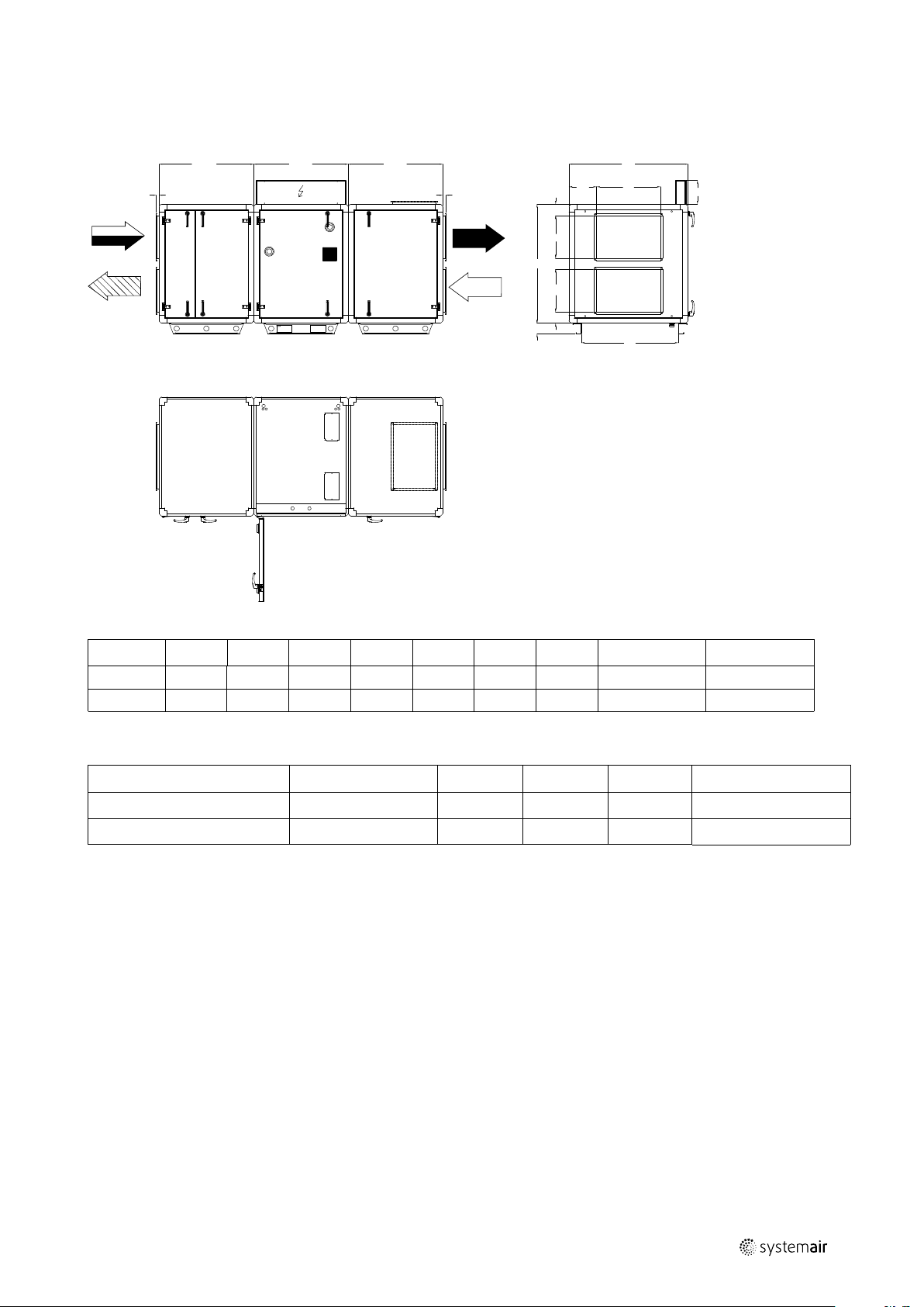
4.2.1 Dimensions and weights Topvex SoftCooler SR09, SR11
Product information |
3
Fig. 1 Dimensions (mm) SR09, SR11 (Drawn as left hand unit)
Model
A B C D E F G
Weight, kg Weight, TOT
SR09 1120 600 400 108 104 260 915 230 665
SR11 1230 800 400 135 165 215 1025 260 695
4.2.2 Technical data
Model Voltage
Topvex SoftCooler SR09
Topvex SoftCooler SR11
Current (A) Power (W)
400V 3N~, 50Hz 15 9230 20 4,1
400V 3N~, 50Hz 15 9230 20 4,8
Fuse, slow Quantity of R410A, kg
208765 | A005
Page 8

| Product information
4
4.3 Components
Fig. 2 Basic components in left hand unit
Position Description
1. Compressor
2.
3.
4.
5.
6.
7.
8.
9.
10. Frequency converter
11.
12.
Condenser coil
Evaporator coil
Filter drier with sight glas
Electronic expansion valve
Drip-tray with drain
Water seal
Cable grommet for external cabling
El. cabinet
Pressure/hot gas switches
Measuring points refrigerant system high/low
208765 | A005
Page 9

4.4 Electrical cabinet
5
4
3
2
1
6
7
8
Product information |
5
Fig. 3 Electrical cabinet
Position Description
1.
2.
3.
4.
5. Frequency converter
6.
7.
8.
Terminal block, mains supply
Circuit breaker (MCB) oil heater
Relays
Terminal block, internal/external connections
DC choke
24V transformer
LCD display
208765 | A005
Page 10

| Transport and storage
6
5 Transport and storage
The Topvex SoftCooler should be stored and transported in such a way that it is protected against physical damage that
can harm panels, handles etc. It should be covered so that dust, rain and snow cannot enter and damage the unit and
its components. The appliance is delivered in one piece containing all necessary components, wrapped in plastic on a
pallet for easy transportation.
When transporting the Topvex SoftCooler use a forklift, but once installed on the floor avoid transfer, the feet can damaged due to lateral loading.
Warning
• The unit is heavy. Be careful during transport and mounting. Risk of injury through pinching. Use
protective clothing.
• Be careful so the unit doesn't tip over.
6 Installation
6.1 Unpacking
Verify that all ordered equipment are delivered before starting the installation. Any discrepancies from the ordered
equipment must be reported to the supplier of Systemair products.
6.2 Where/how to install
Topvex SoftCooler are meant for indoor installation. Place the unit on a horizontal flat surface. It’s important that the
unit is completely levelled before it is put into operation.
The electronic components should not be exposed to lower temperature than 0° C and higher than +50° C.
The following max. temperatures applies for an interference-free operation of the Topvex SoftCooler:
• Outside air max. +33 °C
• Extract air max. +28 °C.
• Ambient temperature max. +28 °C.
When choosing the location it should be kept in mind that the unit requires maintenance regularly and that the inspection doors should be easily accessible. Leave free space for opening the doors and for taking out the main components
(figure 1). General maintenance includes among other things inspection and cleaning of the drip tray and flange coils.
A floor drain must be available in the room so that the condensation water can be drained off (chapter 6.6)
Avoid placing the appliance against a wall, as low frequency noise can cause vibrations in the wall even if the fan
noise-level is acceptable. If this is not possible it is recommended to carefully insulate the wall.
208765 | A005
Page 11

6.3 Installing the unit
6.3.1 Installation
Fig. 4 Installation, left hand unit
Position Description
Supply
Installation |
7
Exhaust
Outdoor
Extract
1.
2.
3.
4.
5.
6.
VAV pressure transmitter supply air (accessories)
VAV pressure transmitter extract air (accessories)
Damper and motor exhaust air (accessories)
Damper and motor outside air (accessories)
Sensor supply air
Topvex SoftCooler SR
6.3.2 Installation procedure
Warning
Beware of sharp edges during mounting and maintenance. Make sure that a proper lifting device is used.
Use protective clothing.
1 Prepare the surface where the unit is to be mounted.
Make sure that the surface is flat, levelled and that it
supports the weight of the unit. Perform the installation in accordance with local rules and regulations.
2 Lift the unit in place.
208765 | A005
Page 12

| Installation
8
3 Level the unit with help of the enclosed mounting
feet
4 Connect the unit electrically to the mains through the
all pole circuit breaker (safety switch), which is enclosed inside the unit on delivery. The wiring between
the safety switch and the unit is led through the top
of the unit casing directly to the electrical connection
box.
See enclosed wiring diagram, and chapter 6.7.1, table
1 for more information.
Warning
The units electrical connection to the mains supply must be preceded by an all pole circuit breaker with a
minimum 3 mm gap.
Danger
• Make sure that the Mains supply to the unit is disconnected before performing any maintenance or
electrical work!
• All electrical connections must be carried out by an authorized installer and in accordance with local rules
and regulations.
208765 | A005
Page 13

6.4 Dividing the Topvex SR air handling unit
Before the installation of Topvex SoftCooler SR the Topvex SR has to be divided (figure 5).
How to split the unit:
Remove the heat exchanger, supply air fan and the extract air filter
A. Loosen the cable connectors in the wall
B. The two halves of the unit are joined using 4 M10 screws, one in each corner
C. Control section
D. Heat recovery section
E. It is possible dismount the gables by removing 6 MRX M6 screws with TH2 bits tool
Reassemble in the reverse order.
Installation |
9
Fig. 5 Left hand version
Note:
When reassembling the pieces make sure they are connected correctly - see cable markings on the side of
the cables.
208765 | A005
Page 14

| Installation
10
6.4.1 Assembley the Topvex SoftCooler SR
Fig. 6 Left hand unit (right hand units are mirrored)
Make sure that the sealing stripes and faces in-between the units halves are undamaged. Place the SoftCooler between
the two air handling units parts and carefully push them completely together. The SoftCooler is joined to the air handling parts by 4 M10 screws, one in each corner.
1. Remove the cover plate on top of Softcooler to access the inner upper mounting screw on the SoftCooler side that
faces the rotary heat exchanger.
2. Remove the exhaust air filter to access the inner upper mounting screw on the Softcooler side that faces the exhaust
air filter.
3. Remove the supply air fan to access the inner upper screw on the Softcooler side that faces the supply air fan.
4. When all 4 screws are in place remount the supply air fan, the exhaust air filter and the cover plate on top of the unit.
208765 | A005
Page 15

Installation |
6.5 Condensation and Heat Insulation
Outdoor air duct and discharge ducts must always be well insulated against condensation. Correct insulation installation
on ducts connected to the unit is especially important. All ducts installed in cold rooms/areas must be well insulated.
Use insulating covering (minimum 100 mm mineral wool) with plastic diffusion barrier. In areas with extremely low outdoor temperatures during the winter, additional insulation must be installed. Total insulation thickness must be at least
150 mm.
Caution
• If the unit is installed in a cold place make sure that all joints are covered with insulation, and tape well
• Duct connections/duct ends should be covered during storage and installation
• Do not connect tumble dryers to the ventilation system
6.6 Condensation drain
Warning
The unit is not to be taken into operation before the included condensation drain and water seal are
connected from the Topvex SoftCooler to the floor drain.
The drain is to be connected to the drain connection under the drip-tray. The drip-tray is located in the bottom of the
Topvex SoftCooler.
11
Use the included plastic connection pipe which is to be cut to the correct height "H" according to the below figure. See
the below table for the relation of hight "H" and maximum under pressure in the unit.
Fig. 7 Dimension and assembly
H (mm) Max. Negative pressure (Pa)
85 500
1
110
135 1000
1
Normal conditions
750
To lead the water from the water seal outlet to the floor drain an extra pipe, not included with the Topvex SoftCooler, is
needed. Connect this pipe and make sure that the slope is at a minimum 1:200 to the floor drain and also that the complete drain installation are in a frost free space.
Fig. 8 Pipe to floor drain
208765 | A005
Page 16

| Installation
12
6.7 Electrical connection
Danger
• Make sure that the Mains supply to the unit is disconnected before performing any maintenance or
electrical work!
• All electrical connections must be carried out by an authorized installer and in accordance with local rules
and regulations.
• Operation in the refrigerant cycle and handling refrigerants must be performed by certified personnel.
Fig. 9 Electrical connection, left hand unit
Cable fastener
Control cable
Power supply
1. Wire the prepared control cable from the Topvex SoftCooler electrical connection box to the Topvex SR electrical cabinet (in the supply air part).
Use the prepared grommet to enter the cabinet and secure the cable along its way on top of the unit using the self
adhesive cable fasteners.
2. Connect the wires to the terminal block in the electrical cabinet according to labeling on the wires and electrical wiring diagram. See also chapter 6.7.1 Internal electrical connections.
3. Connect the cooler unit electrically to the mains (400V 3~, 50 Hz) through the all pole curcuit breaker (safety switch)
which is enclosed inside the unit at delivery. The power cable is led directly into the Topvex SoftCooler electrical connection box. Dimension the wire and fuses according to the electrial data (figure 4.2.2)
4. Do the electrical connections for the Topvex SR air handling unit according to the installation instruction that follows
that unit.
208765 | A005
Page 17

6.7.1 External/Internal connections
See also the enclosed wiring diagram.
Mains supply is the only external connection that should be connected to the Topvex SoftCooler.
Table 1 External connections
Terminal
block
PE
Description
Ground
Remark
Installation |
13
N N
L1 L1
L2 L2
L3 L3
The already prepared operating cable in Topvex SoftCooler is to be drawn to the electrical cabinet in the supply part of
the Topvex air handling unit and connected to the terminal blocks with the same numbers as the cable markings.
Table 2 Internal connections
Terminal
block
G G 24V AC
4
10
15 DO
74 DI
90
94 AO
DI ref Referens
DO ref Referens
AO ref Reference
Earthed neutral (supply voltage)
Phase (supply voltage)
Phase (supply voltage)
Phase (supply voltage)
Description
A signal from control unit for starting Step controller 1 step 1
indicates a cooling demand. The signal controls relay R1 that is
then starting the compressor.
Alarm indication cooling (Malfunction cooling (SEQ-C).
Control signal from control unit for cooling. Controls the frequency
converter "FC".
400V 3N~, 50Hz
supplied via safety
switch
Remark
24V AC, 0.5A
NO
0-10V DC
208765 | A005
Page 18

Function Description
RC
RM
HE
EV
CO
FC
HPS
CPR
EV
CO
FC
HPS
CPR
|
14
7 Function Description
Fig. 10 Left hand unit
Position Description
EF
SF
SS
OS
ETS Temp. sensor extract air
UC
RC
RM Rotor motor
HE
DO
DEH
FC Frequency converter
CPR Compressor
EV Evaporator
CO
HPS
Extract air fan
Supply air fan
Temp. sensor supply air
Temp. sensor outdoor air
Control unit
Rotor control
Exchanger
Damper outdoor air (accessory)
Damper exhaust air (accessory)
Condenser
Condenser pressure sensor
OT/ET Overheating/Max. temp switches
FGS/FGE Air filter pressure switches
7.1 General
Control unit (UC) senses the temperature via the extract temperature sensor (ETS) and then keep the set extract temperature by sequence controlling the compressor (CPR), heat exchanger (HE) and hot water- /electrical heater (HWL/H,
ELH). The temperature sensor in the supply air (SS) is min. and max. limiting the supply air temperature.
7.2 Power control
The compressor (CPR) are step-less controlled between, in the frequency converter (FC), set minimum and maximum
frequency.
7.3 Power limitation
The programmable controller is continuously sensing the condensing pressure via the high pressure sensor (HPS) and
gradually slows down the speed of the compressor (CPR), if the pressure exceeds the set limitation value. This is done
to avoid a high pressure alarm.
Note:
This instruction contains functions for the Topvex SoftCooler SR, for a complete description of functions see
" SR 09,11, TR 09-15 Installation instruction".
208765 | A005
Page 19

8 Commissioning protocol
Company:
Responsible:
8.1 General
Commissioning protocol |
15
Customer: Date:
Object/unit:
Item no:
Model/size Serial no:
8.2 Installation protocol
Moment Done Note
Control report cooling concerning installation established.
(Application shall in some cases be done, see chapter 3,
Refrigerant Control/Reporting).
All unit parts undamaged.
Installation carried out according to instructions (see
chapter 6.4.1, Assembly the Topvex SoftCooler.
Condensation drain connected (see chapter 6.6,
Condensation drain).
Mains supply connected via the Safety switch (see chapter
6.7, Electrical connection).
Internal operating cable connected (see chapter 6.7.1,
External/Internal connections).
Supply and extract airflow adjusted
Installation:
Installation address:
Designation:
8.3 Preparing control unit
To receive correct functions the following settings must be done in the control unit. Log in with service level using password 0612.
Moment Done Note
Select the menu Configuration > Functions >
Function activation > Heating/Cooling
sequence setup:
• Choose Cooling
• Set Type of cooler to DX
• Set Type of feedback to Alarm
Select the menu Configuration > Functions >
Function activation > Heating/Cooling
sequence setup:
• Choose Step controller 1
• Set Step control sequence to Cooling
• Set Number of steps to 1
Select the menu Configuration > Functions >
Function activation:
• Check that Temperature control type is set as
Extract air cascade or Room cascade
Select the menu Configuration > Functions >
Temperature control:
• Set Cooling recovery mode to Off
Select the menu Configuration > I/O allocation
settings > Digital outputs:
Set Signal for Step controller 1 step 1 to DO5
208765 | A005
Page 20

| Commissioning protocol
16
Moment Done Note
Select the menu Configuration > I/O allocation
settings > Digital inputs:
• Set signal for Extended operation normal speed
to Select I/O (or to any other free DI)
• Set signal for Feedback cooling (SEQ-C) to DI4
Select the menu Data & Settings > Temperature
control > Cooling:
Set Min switch time to 1s
Set Step 1 start point to 10%
Set Step 1 stop point to 0%
Set Reduction of min limit supply air if active
DX-cooling to 0°C
Note:
Note: DI4 cannot be used for extended run
when Topvex SoftCooler is used.
8.4 Before compressor start
To avoid damage on the compressor the oil in the compressor crankcase must be heated before the first start.
Moment Done Note
Stop the Supply- and extract fan (via the Topvex air
handling units safety switch)
Turn on the mains supply for the Topvex SoftCooler via the
safety switch, make sure that the voltage is on (the display
in the frequency converter lights up) Wait for minimum 2
hours so that the oil will reach about +30° C!
8.5 Control cooling operation
Moment Done Note
Start the Supply- and extract fan (via the Topvex air
handling units safety switch). Run the unit on dimensioning
airflows.
Start the compressor by establishing a 100% cooling
demand:
• Log in with service level using password 0612
• Select menu Data & Settings > In-/Output
status > Heating/Cooling sequences
• Set Mode for Cooling to Manual
• Set Manual for Cooling to 100%
Run the compressor for at least 10 minutes.
Then read the Extract-, Outdoor- and Supply air
temperature via the display of the control unit (in the menu
Temperature).
Let the compressor run.
Measure the hotgas- and liquid line temperature with a
strap-on temperature detector.
Supply air ________________m3/h
Extract air _______________m
Outdoor air temperature __________°C
Supply air temperature ___________°C
Extract air temperature __________°C
Hotgas temperature ___________°C
Liquid line temperature _________°C
3
/h
208765 | A005
Page 21

Moment Done Note
Keep the compressor running.
Read the below values via the display of the frequency
converter, see section ”Frequency converter, quick guide”,
in Operating and Maintenance Instructions. First set the
parameter for reading, then let the door of the Topvex
SoftCooler be closed for at least 5 minutes before reading:
• Output frequency (Param d001)
• Output current (Param d002)
• Condenser pressure (Param d004)
Output frequency __________________Hz
Output current ____________________Hz
Condenser pressure ______________bar
Note:
Important! Restore the cooling operation to Auto:
• Log in to the control unit as Service (0612)
• Select menu Data & Settings > In-/Output
status > Heating/Cooling Sequences
• Set Mode for Cooling to Auto
Notes:
Commissioning protocol |
17
208765 | A005
Page 22

208765 | A005
Page 23

208765 | A005
Page 24

Systemair Sverige AB
Industrivägen 3
SE-739 30 Skinnskatteberg, Sweden
Phone +46 222 440 00
Fax +46 222 440 99
www.systemair.com
Topvex SoftCooler SR09, SR11Access control system · Installation instructions · 208765 · en_GB · 2019-12-19 · A005
 Loading...