

Page 1

Fire Safety Products
S-BM2
Smoke Control Damper - MA Multi
User Manual
Page 2
2/48 | User Manual S-BM2 | 202010
Table of Contents
Introduction . . . . . . . . . . . . . . . . . . . . . . . . . . 3
Warnings . . . . . . . . . . . . . . . . . . . . . . . . . . . . 4
Operating Conditions . . . . . . . . . . . . . . . . . . . . . 4
Installation . . . . . . . . . . . . . . . . . . . . . . . . . . . 5
Installation Methods . . . . . . . . . . . . . . . . . . . . 6
Opening Preparation for S-BM2 Installation. . . . . . . . 8
Installation Distances . . . . . . . . . . . . . . . . . . . 10
Manipulation of S-BM2 . . . . . . . . . . . . . . . . . . 11
Wet Installation . . . . . . . . . . . . . . . . . . . . 14
Dry Installation . . . . . . . . . . . . . . . . . . . . . 18
Fit Installation . . . . . . . . . . . . . . . . . . . . . 22
Installation in the Duct Made of Promatect Boards . 26
Installation in the Duct Made of Sheet Metal. . . . . 30
Installation on the Horizontal Duct . . . . . . . . 34
Installation on the Vertical Duct . . . . . . . . . 38
Electrical Connections . . . . . . . . . . . . . . . . . . . . . 42
Operation Manual . . . . . . . . . . . . . . . . . . . . . . . 44
Smoke Control Damper Functionality Check . . . . . . . . . 44
Smoke Control Damper Inspection . . . . . . . . . . . . . . 44
Warranty Conditions . . . . . . . . . . . . . . . . . . . . . . 45
Operating Journal . . . . . . . . . . . . . . . . . . . . . . . 46
Warranty Service . . . . . . . . . . . . . . . . . . . . . . . 48
Good to know
Current information on all products is
available at www.design.systemair.com
Page 3
Introduction
This is the original installation, inspection and operating instructions document for the S-BM2 smoke control damper.
EVERY S-BM2 SMOKE CONTROL DAMPER NEEDS TO BE INSTALLED IN ACCORDANCE WITH THIS DOCUMENT!
S-BM2
Multiblade smoke control damper with or without mesh for installations in the wall, on the vertical or horizontal duct.
Dimension range (mm): W × H = 200 × 425 up to 1000 × 1225
1396-CPR-0157
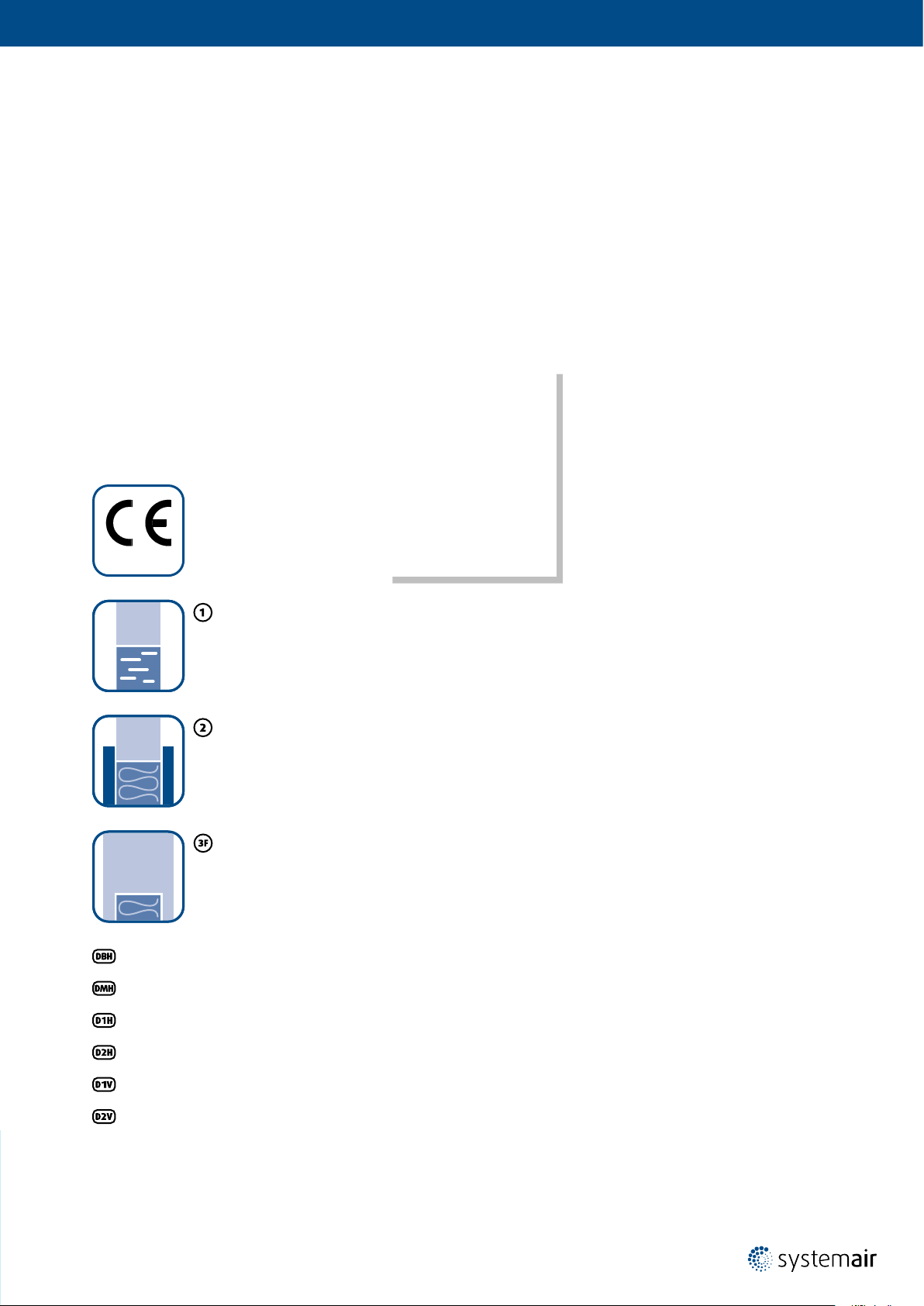
Wet Installation
Maximum performance up to EI120S
Using Plaster/Mortar/Concrete Filling
Dry Installation
Maximum performance up to EI120S
Using Mineral Wool and Cover Boards
Fit Installation
Maximum performance up to EI120S
Wall Installation Using Mineral Wool
Installation in the Duct Made of Promatect Boards
Installation in the Duct Made of Sheet Metal
Installation on the Horizontal Duct - Flush with Edges
Installation on the Horizontal Duct - Surface
Installation on the Vertical Duct - Flush with Edges
Installation on the Vertical Duct - Surface
NOTE: *Fire resistivity depends on the type of installation.
Page 4

4/48 | User Manual S-BM2 | 202010
Warnings
Some damper parts may have sharp edges – therefore, to protect yourself from harm, please use gloves during
damper installation and manipulation. In order to prevent electric shock, re or any other damage which could result
from incorrect damper usage and operation, it is important to:
1. ensure that installation is performed by a trained person.
2. follow the written and depicted instructions provided within this User Manual closely.
3. perform damper inspection in accordance with this User Manual.
4. check the damper’s functionality as per the
install the smoke control damper. This procedure prevents the installation of a damper that has been damaged
during transportation or handling.
IMPORTANT: Do not install non-functioning dampers!
“Smoke Control Damper Functionality Check” chapter before you
Operating Conditions
S-BM2 smoke control damper is intended:
• for installation in places which are protected against weather disruptions.
• for ducts distributing air without any mechanical or chemical contamination.
• for maximum air ow velocity 12 m/s.
• for storage temperature minimum -20°C and maximum 50°C.
Accessory:
• K1-S-BM2: Kit for Duct Installation
Page 5

Installation
• The duct connected to the smoke control damper must be supported or hung in such a way that the damper does
not carry its weight. The damper must not support any part of the surrounding construction or wall which could
cause damage and consequent damper failure.
• Easy access to mechanism and internal parts during inspection must be considered during damper placement.
• According to the standard EN 1366-2, the distance between the smoke control damper bodies must be at least 200 mm.
• The distance between smoke control damper and the adjacent wall/ceiling and the smoke control damper must be
at least 75 mm.
• When the S-BM2 smoke control damper is installed into a smoke and re partition structure, it must be placed
so that the damper blades in its closed position are located inside this structure.
• The gap in the installation opening between the smoke control damper and the wall/ceiling can be increased
by up to 50% of the gap area or decreased to the smallest amount possible that still provides sufcient space
for the installation of the seal.
• When using non-original grilles, the gap between the damper blade in open position and the self-standing grill,
mesh, louvre must be at least 200 mm according to EN 1366-10.
• The smoke control damper must be earthed after being installed into or onto the duct.
• Lists of all permitted installation methods are provided on following pages.
Page 6
6/48 | User Manual S-BM2 | 202010
Installation Methods
S-BM2 Smoke control dampers are CE certied following the Construction Products Regulation according to EN 12101-8:2011.
Tested according to EN 1366-10:2011 + A1:2017, EN 1366-2:2015 and classied according to EN 13501-4:2016.
The smoke control damper together with its installation form an inseparable part of the re resistivity rating.
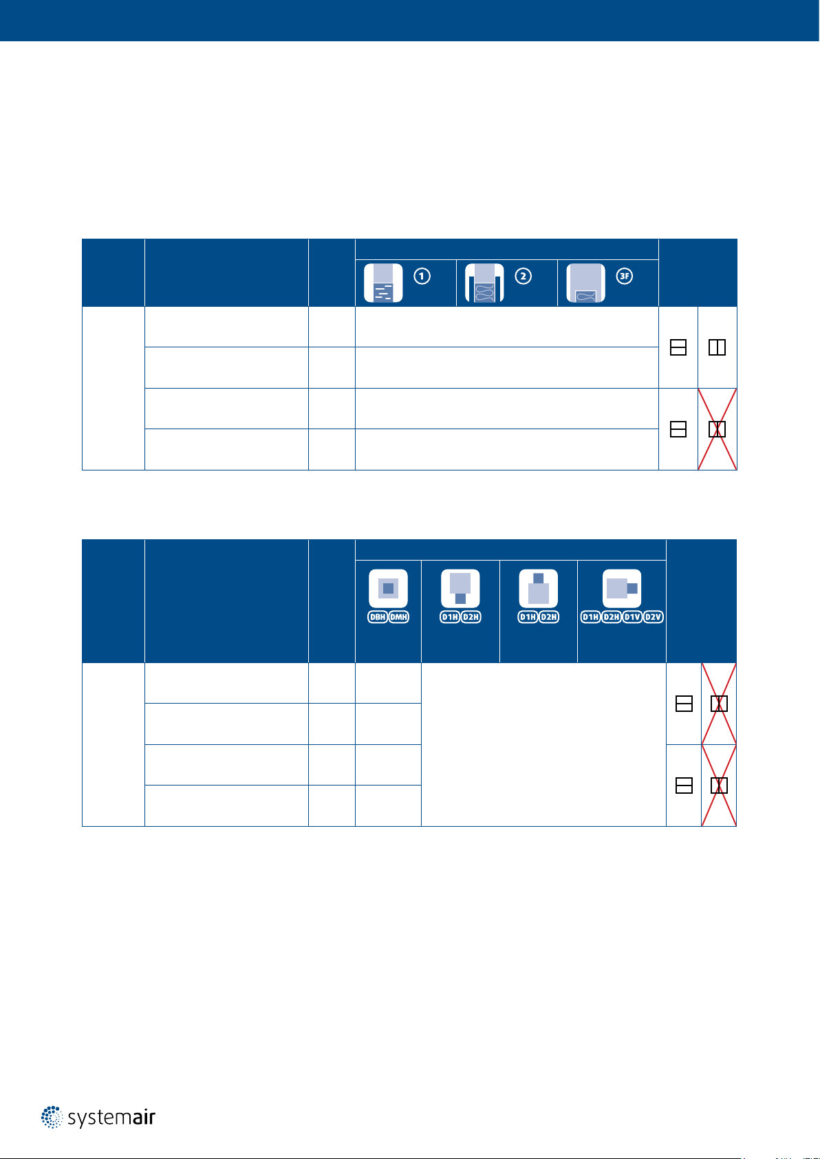
Tab. 1: Fire resistivity of S-BM2 - wall mounted
Dimension
Range
Classication
(mm)
200 × 425
i ↔ o) S1000 C
EI90 (v
ew
EI90 (how i ↔ o) S1000 C
MAmulti Wall
mod
MAmulti
mod
up to
1000 × 1225
i ↔ o) S1000 C
EI120 (v
ew
EI120 (how i ↔ o) S1000 C
MAmulti Wall
mod
MAmulti
mod
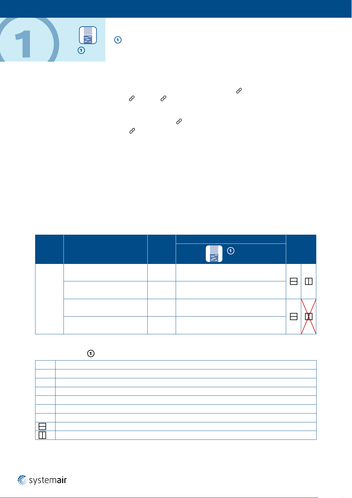
Tab. 2: Fire resistivity of S-BM2 - duct mounted
Dimension
Range
Classication
(mm)
Supporting
Construction
Floor/
ceiling
Floor/
ceiling
Duct Orientation
In the Duct
Construction Type/Minimal Thickness (mm)
Wet Dry Fit
Rigid/125
Flexible/125
-
Rigid/125
Flexible/125
-
Applicable Duct Tested per Standard
On the Duct/
Bottom Mounted
On the Duct/
Top Mounted
On the Duct/
Side Mounted
Allowed
Blade Axis
Orientation
Allowed
Blade Axis
Orientation
200 × 425
up to
1000 × 1225
i ↔ o) S1000 C
EI90 (v
ed
EI90 (hod i ↔ o) S1000 C
i ↔ o) S1000 C
EI120 (v
ed
EI120 (hod i ↔ o) S1000 C
MAmulti
mod
MAmulti
mod
MAmulti
mod
MAmulti
mod
Horizontal
duct
Vertical
duct
Horizontal
duct
Vertical
duct
EN 1366-9,
EN 1366-8
-
EN 1366-9,
EN 1366-8
-
EN 1366-9,
EN 1366-8
Page 7

Legend
Wet Installation
Dry Installation
Fit Installation
Damper placed on duct surface, bottom side of the duct
Damper placed on duct surface, top side of the duct
Damper placed on duct surface, left and right side of the duct
Damper placed within the duct canal, outside of supporting construction
Installation in the duct made of promatect boards
Installation in the duct made of sheet metal
Installation on the horizontal duct - ush with edges
Installation on the horizontal duct - surface
Installation on the vertical duct - ush with edges
Installation on the vertical duct - surface
Horizontal blade axis orientation of the damper
Vertical blade axis orientation of the damper
Page 8
8/48 | User Manual S-BM2 | 202010
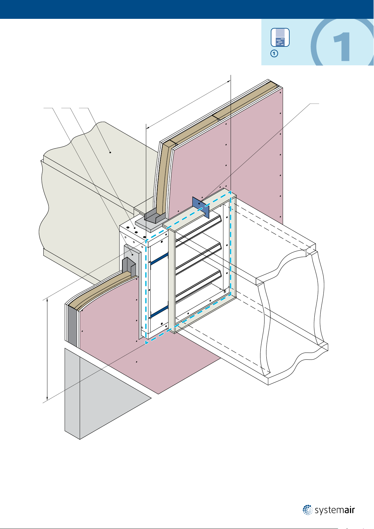
Opening Preparation for S-BM2 Installation
The S-BM2 smoke control damper can be installed in a supporting construction between zones classied
as “multi-multi”, “multi-single” and “single-multi”.
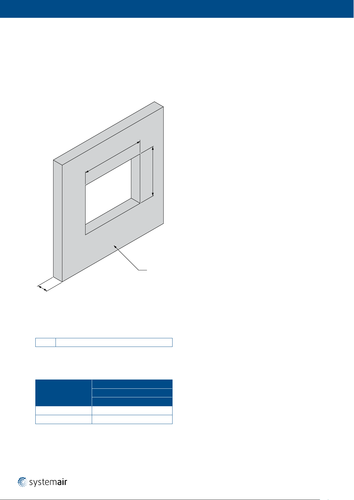
Opening Preparation for a Rigid Wall
1
W
H
1
s
Fig. 1: Rigid wall/ceiling with a rectangular opening
NOTE: Dimensions W
and H1 are dened in every installation
1
Legend
1 Concrete/Masonry/Cellular Concrete
Tab. 3: Thickness of tested wall
Minimum s (mm)
Fire Resistivity
Concrete/Masonry/Cellular Concrete
90 125 ± 10
120 150 ± 10
1
Wall
Page 9
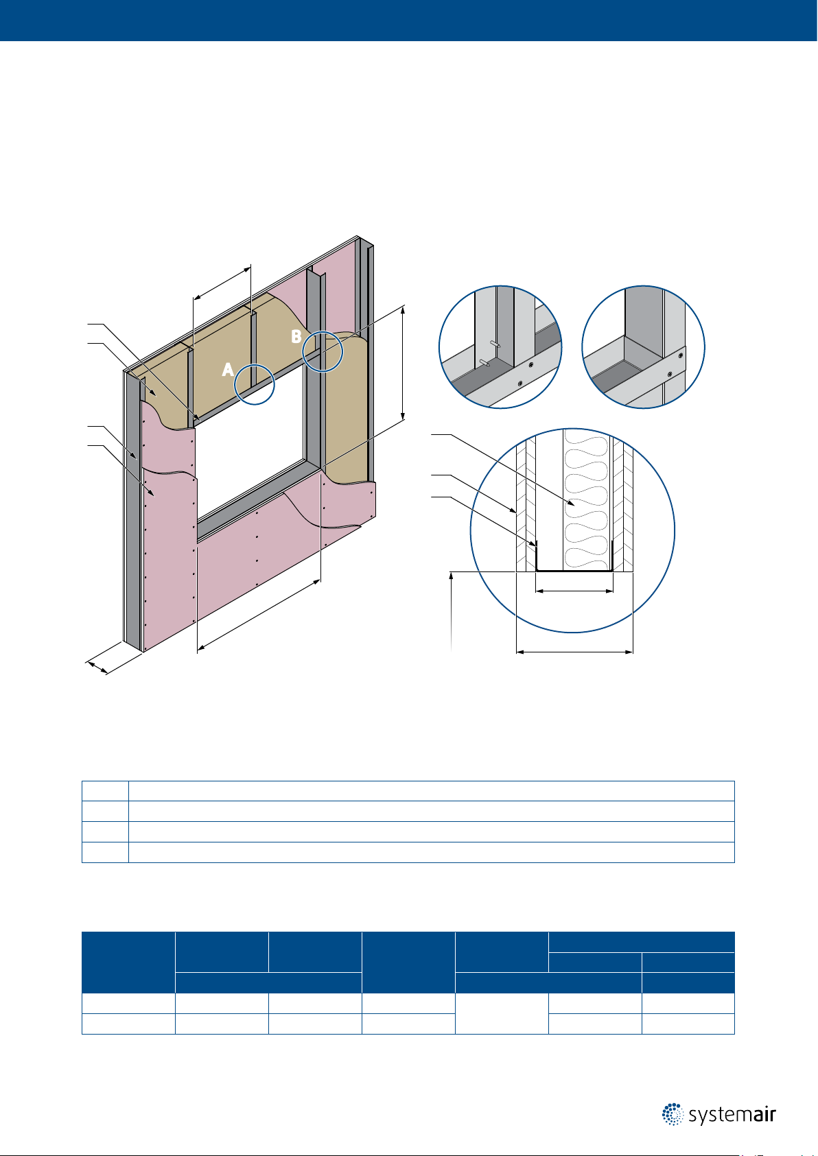
Opening Preparation for a Flexible Wall
25
6
.
x
ma
3
4
B
A
A
H
1
B
2
1
4
1
3
W
1
× W
H
1
1
s
Fig. 2: Flexible (plasterboard) wall with a rectangular opening and vertical cross-section (right)
Legend
1 On each side - 2 layers of plasterboard reproof plate type F, EN 520 (thickness see Tab. 4)
2 Vertical CW-proles (proles with s
3 Horizontal UW-proles (prole with s
4 Mineral wool; thickness/cubic density see Tab. 4)
based on re resistivity, see Tab. 4)
CW
based on re resistivity, see Tab. 4)
CW
s
CW
s
Tab. 4: Thickness of tested wall
Fire Resistivity
90 125 75 B, C
120 150 100 C 60 ... 70 85 ... 115
Minimum s Minimum s
(mm) (mm) (kg/m
CW
Allowed Metal
Stud Group
Thickness
of Plasterboards
12,5
Thickness Cubic Density
40 ... 50 80 ... 115
Insulation
3
)
Page 10
10/48 | User Manual S-BM2 | 202010
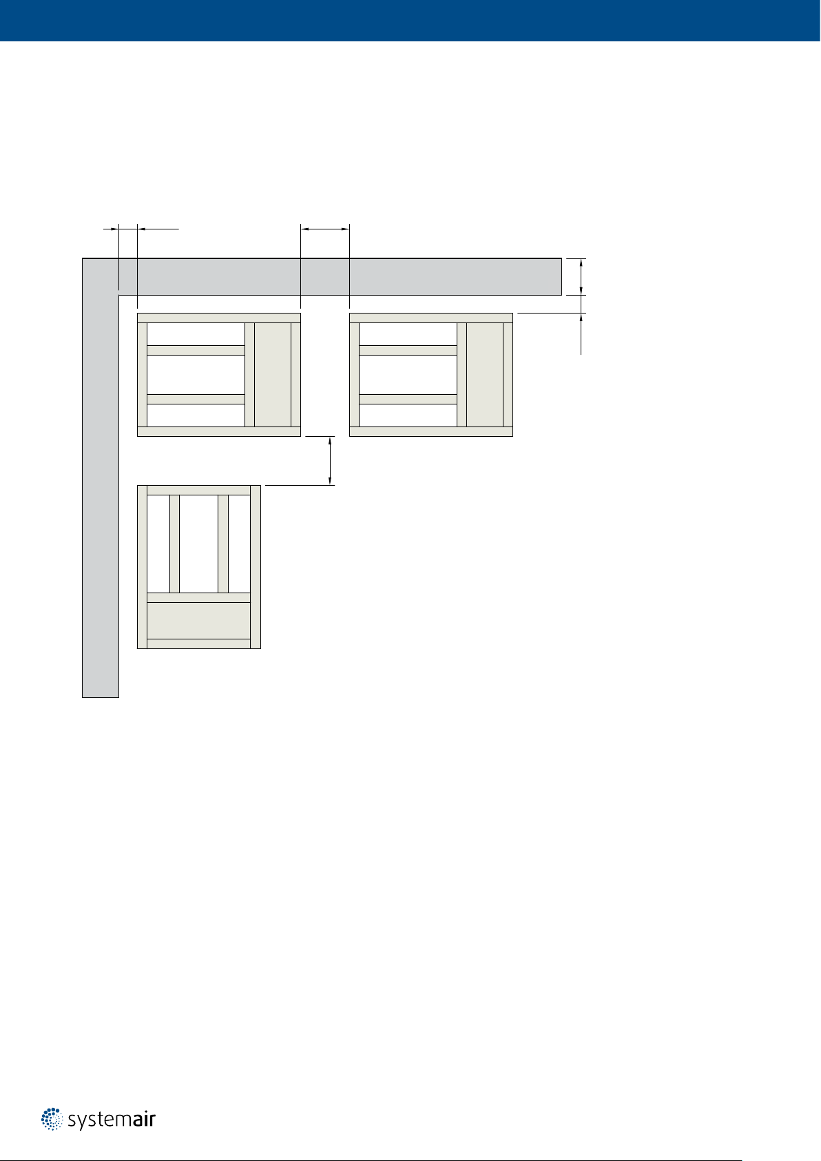
Installation Distances
According to the EN 1366-2 standard, the minimum distance from the wall or ceiling to the damper body is 75 mm.
For multiple crossings through a re resistive wall, the minimum distance between two damper bodies is 200 mm.
This applies for distances between the damper body and a nearby foreign object crossing the re resistive wall.
Damper clearances vary from the type of mechanism and their rotation (see Fig. 3).
≥200≥75
≥75 s
Fig. 3: Installation distances between damper bodies
≥200
Page 11
Manipulation of S-BM2
The S-BM2 is made of boards and can thus be considered fragile. Handling and manipulation must be done with care.
Smaller dimensions can be manipulated and placed in the installation opening by two persons. Bigger dimensions are
supplied with wooden blocks, those serve as support for suitable lifting equipment (forklift, crane).
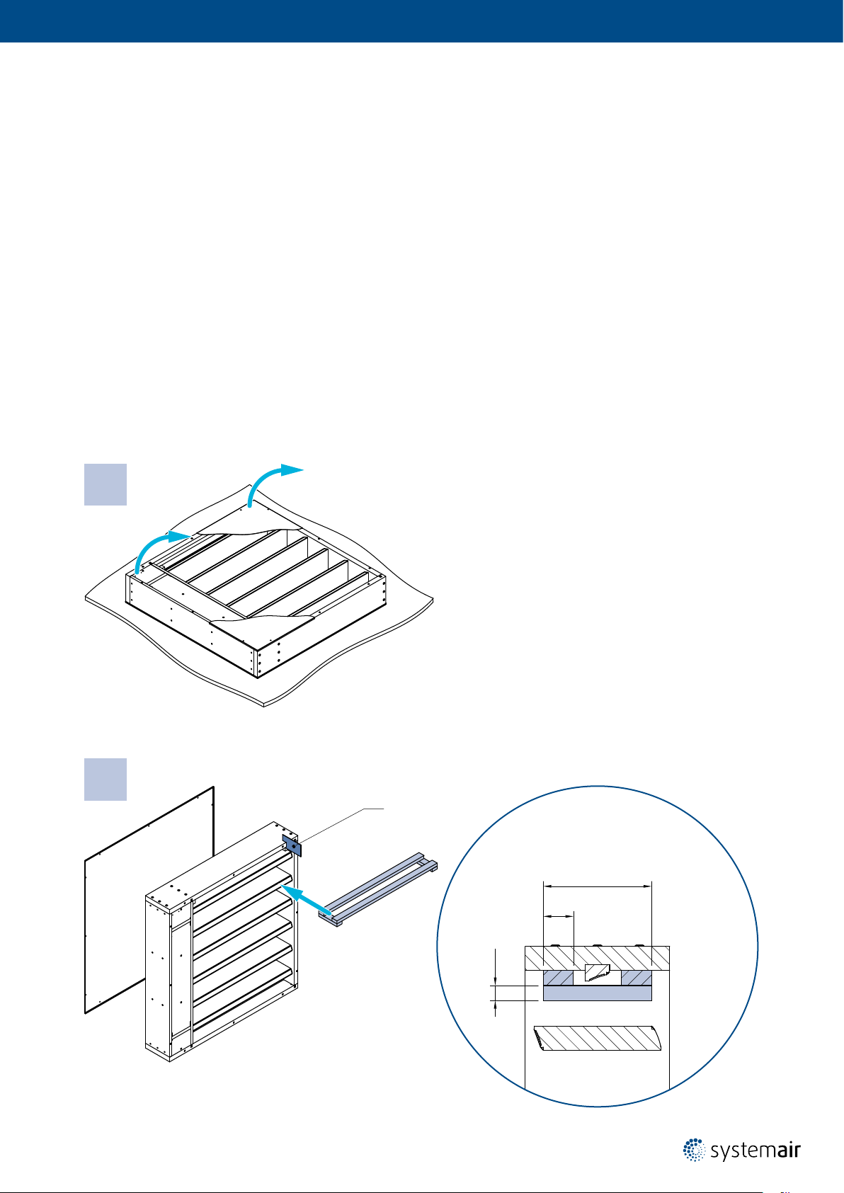
Please follow both textual and graphic instructions (Fig. 4 up to Fig. 10):
1. Unpack the damper and place it in vertical position.
2. Remove grille and place the holder between the upper-most blade and the frame.
3. Carefully lift the smoke control damper with the forklift, crane.
4. Prepare the opening, damper hanger, connection surfaces and/or lling as per the desired installation type.
5. Place the smoke control damper in the opening (wall installation) or on the opening (duct installation).
6. Once the smoke control damper has been placed x the damper to ductwork:
a) For wall installation - insert the lling as per desired installation.
b) For duct installation – x the hangers so that the weight of the damper is supported.
7. Carefully remove the fork.
8. Remove the wooden support.
9. If the ductwork ends with the damper – install a grille or grilles.
1.
Fig. 4: Unpack the damper and place it in vertical position
2.
Y₁
Fig. 5: Remove grille and place the holder between the upper-most blade and the frame.
NOTE: Y1 = Cutting plane
180
50
25
Page 12

12/48 | User Manual S-BM2 | 202010
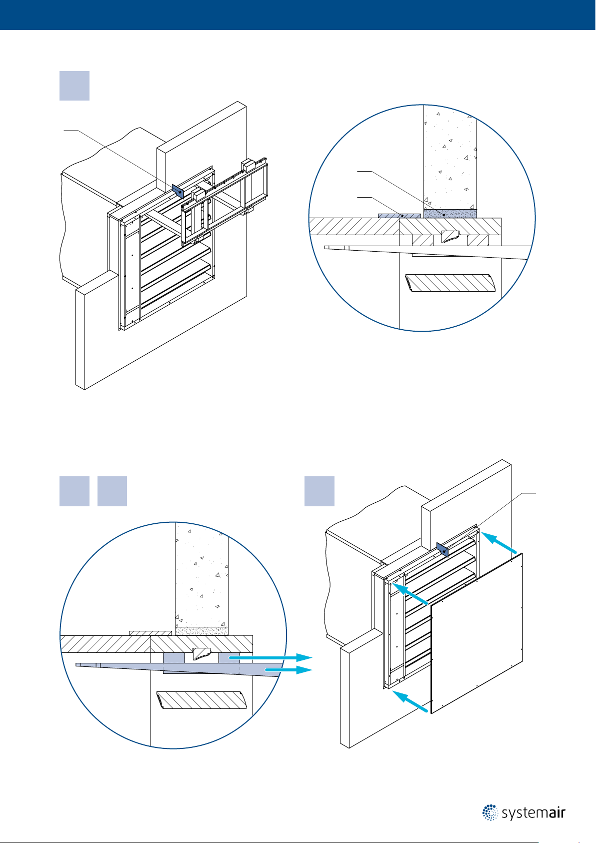
3.
Y₂
Fig. 6: Carefully lift the smoke control damper with the forklift, crane.
= Cutting plane
NOTE: Y
2
4. 5.
Fig. 7: Prepare the opening, damper hanger, connection surfaces and/or lling as per the desired installation type
Place the smoke control damper in the opening (wall installation) or on the opening (duct installation).
Page 13
6.
Y₃
a)
b)
Fig. 8: Once the smoke control damper has been placed x the damper to ductwork:
a) For wall installation - insert the lling as per desired installation.
b) For duct installation – x the hangers so that the weight of the damper is supported.
= Cutting plane
NOTE: Y
3
7. 8. 9.
Y₄
Fig. 9: Carefully remove the fork. Remove the wooden support.
Fig. 10: If the ductwork ends with the damper – install a grille or grilles.
= Cutting plane
NOTE: Y
4
Page 14
14/48 | User Manual S-BM2 | 202010
Wet
1. The supporting construction opening must be prepared in a way depicted in the “Opening Preparation for
S-BM2 Installation” section (as per
The exible wall opening must be reinforced as per the standards for plasterboard walls.
The opening dimensions are driven by the nominal dimensions of the damper with added clearance.
The opening will be with the dimensions of W
2. Insert the closed damper as per the
the damper blade is in the wall. For damper widths greater than 600 mm, it is recommended to use a duct support
inside the damper during installation to avoid any damage caused to the damper housing by the weight of the lling.
3. Fill in the area between the wall and the damper with gypsum plaster or mortar or concrete lling (3)
while paying attention to prevent the fouling of the damper’s functional parts, which could limit its correct
functionality. The best way is to cover the functional parts during installation.
To prevent seepage of the lling material, use of boards is recommended.
First, let the plaster or mortar or concrete lling harden and then perform the next steps.
4. After the lling hardens, remove the duct support from inside of the damper.
5. If needed, uncover and clean the damper after installation.
6. Check the functionality of the damper.
Wet Installation
Wall Installation Using Plaster/Mortar/Concrete Filling
Fig. 1 and Fig. 2). Opening surfaces must be even and cleaned off.
and H1 ( Fig. 11).
1
“Manipulation of S-BM2” section into the middle of the opening so that
Dimension
Range
(mm)
200 × 425
up to
1000 × 1225
Classication
i ↔ o) S1000 C
EI90 (v
ew
EI90 (how i ↔ o) S1000 C
i ↔ o) S1000 C
EI120 (v
ew
EI120 (how i ↔ o) S1000 C
MAmulti Wall
mod
MAmulti Floor/ceiling -
mod
MAmulti Wall
mod
MAmulti Floor/ceiling -
mod
Supporting
Construction
Legend for gures of Wet installation
1 Smoke control damper S-BM2
2 Connected ductwork made of Promatect-L500 boards (min. 500 kg/m
3 Plaster/mortar/concrete lling
4 Grille
5 Nails or pins per ductwork manufacturer instructions
6 Fire resistive coating Promat K84 (Promat)
Y Cutting plane
Horizontal blade axis orientation of the damper
Vertical blade axis orientation of the damper
Construction Type/Minimal Thickness (mm)
Wet
Rigid/125
Flexible/125
Rigid/125
Flexible/125
3
, Promat)
Allowed
Blade Axis
Orientation
Page 15
Wet
13
2
W₁=(W+270)+40
Y
H₁=(H+80)+40
Fig. 11: Wet installation of S-BM2 smoke control damper
Page 16

16/48 | User Manual S-BM2 | 202010
125
Wet
Legend
Y
Y
Y
Y
Y
Y
Y
Y
Y
Y
Cross-section of Wet installation in exible wall (aligned on the outside)
1
Cross-section of Wet installation in rigid wall (aligned on the outside)
2
Cross-section of Wet installation in exible wall (aligned on the inside)
3
Cross-section of Wet installation in rigid wall (aligned on the inside)
4
Cross-section of Wet installation in exible wall ended with grille (aligned on the outside)
5
Cross-section of Wet installation in rigid wall ended with grille (aligned on the outside)
6
Cross-section of Wet installation in exible wall ended with grille (aligned on the inside)
7
Cross-section of Wet installation in rigid wall ended with grille (aligned on the inside)
8
Cross-section of Wet installation in exible wall ended with grille on both sides
9
Cross-section of Wet installation in rigid wall ended with grille on both sides
10
Y₁
12,5
≥50
≥50
3 1
5
6
2
10
≥50
20
Y₂
50
≥50
Y₃
≥10≥10
H₁ × W₁
240
Y₄
Page 17

Wet
125
125
Y₅
50
12,5
43 1
5
6
2
10
≥50
20
≥10≥10
H₁ × W₁
≥50
240
Y₇
Y₆
Y₈
Y₉
12,5
≥50
240
13
4
Y
10
20
≥10≥10
H₁ × W₁
Page 18

18/48 | User Manual S-BM2 | 202010
Dry Installation
Dry
Wall Installation Using Mineral Wool and Cover Boards
1. The supporting construction opening must be prepared in a way depicted in the “Opening Preparation for
S-BM2 Installation” section (as per
Fig. 1 and Fig. 2). Opening surfaces must be even and cleaned off.
The exible wall opening must be reinforced as per the standards for plasterboard walls.
The opening dimensions are driven by the nominal dimensions of the damper with added clearance.
The opening will be with the dimensions of W
2. Insert the damper as per the
“Manipulation of S-BM2” section into the middle of the opening so that the damper
and H1 ( Fig. 12).
1
blade is in the wall. For damper widths greater than 600 mm, it is recommended to use a duct support inside
the damper during installation to avoid any damage caused to the damper housing by the weight of the lling.
3. Fill in the area between the wall and the damper with mineral wool (3) with a density of at least 100 kg/m
3
thoroughly but in such a way that will not deform the duct.
4. Close the gap between the damper and the mounting opening, use gypsum boards (7) with screws (8)
which x the gypsum boards to wall.
5. All the gaps between gypsum boards and the wall and between gypsum boards and the connected ductwork
made of Promatect boards need to be lled with putty for gypsum boards (9; e.g. Rigips Super)
6. Check the functionality of the damper.
Dimension
Range
(mm)
200 × 425
up to
1000 × 1225
Classication
i ↔ o) S1000 C
EI90 (v
ew
EI90 (how i ↔ o) S1000 C
EI120 (v
EI120 (how i ↔ o) S1000 C
i ↔ o) S1000 C
ew
Supporting
Construction
MAmulti Wall
mod
MAmulti Floor/ceiling -
mod
MAmulti Wall
mod
MAmulti Floor/ceiling -
mod
Construction Type/Minimal Thickness (mm)
Legend for gures of Dry installation
1 Smoke control damper S-BM2
3
2 Connected ductwork made of Promatect-L500 boards (min. 500 kg/m
3 Mineral wool lling (min. 100 kg/m³)
4 Grille
5 Nails or pins per ductwork manufacturer instructions
6 Fire resistive coating Promat K84 (Promat)
7 Gypsum boards
8 Screws for xing gypsum boards to: exible wall (TN 3,5×35)/rigid wall (HUS-CR 8×65)
9 Putty for gypsum boards, e.g. Rigips Super
Y Cutting plane
Horizontal blade axis orientation of the damper
Vertical blade axis orientation of the damper
, Promat)
Dry
Rigid/125
Flexible/125
Rigid/125
Flexible/125
Allowed
Blade Axis
Orientation
Page 19

Dry
713
2
W₁=(W+270)+40
Y
H₁=(H+80)+40
Fig. 12: Dry installation of S-BM2 smoke control damper
Page 20

20/48 | User Manual S-BM2 | 202010
12,5
Dry
Legend
Y
Y
Y
Y
Y
Y
Y
Y
Y
Y
Cross-section of Dry installation in exible wall (aligned on the outside)
1
Cross-section of Dry installation in rigid wall (aligned on the outside)
2
Cross-section of Dry installation in exible wall (aligned on the inside)
3
Cross-section of Dry installation in rigid wall (aligned on the inside)
4
Cross-section of Dry installation in exible wall ended with grille (aligned on the outside)
5
Cross-section of Dry installation in rigid wall ended with grille (aligned on the outside)
6
Cross-section of Dry installation in exible wall ended with grille (aligned on the inside)
7
Cross-section of Dry installation in rigid wall ended with grille (aligned on the inside)
8
Cross-section of Dry installation in exible wall ended with grille on both sides
9
Cross-section of Dry installation in rigid wall ended with grille on both sides
10
125
Y₁
8
7 9
12,5
≥50
13
5
6
Y₂
2
10
10020
50
Y₃
≥50
≥10
≥10
H₁ × W₁
240
Y₄
Page 21

Dry
12,5
125
12,5
Y₅
50
125
12,5
7
8
5
6
2
10
9 13
≥50
≥50
≥50
240
≥10≥10
Y₇
Y₆
10020
H₁ × W₁
Y₈
Y₉
12,5
≥50
≥50
240
13
4978
Y
10
10020
≥10≥10
H₁ × W₁
Page 22

22/48 | User Manual S-BM2 | 202010
Fit Installation
Fit
Wall Installation Using Mineral Wool
1. The supporting construction opening must be prepared in a way depicted in the “Opening Preparation for
S-BM2 Installation” section (as per
Fig. 1 and Fig. 2). Opening surfaces must be even and cleaned off.
The exible wall opening must be reinforced as per the standards for plasterboard walls. The opening dimensions
are driven by the nominal dimensions of the damper with added clearance. The opening will be with the
dimensions of W
2. Insert the closed damper as per the
and H1 ( Fig. 13).
1
“Manipulation of S-BM2” section into the middle of the opening so that
the damper blade is in the wall. For damper widths greater than 600 mm, it is recommended to use a duct support
inside the damper during installation to avoid any damage caused to the damper housing by the weight of the lling.
3. Fill in the area between the wall and the damper with mineral wool (3) with a density of at least 100 kg/m
3
thoroughly but in such a way that will not deform the duct.
4. All the gaps between the wall and the damper and between wall and the connected ductwork made
of Promatect boards need to be lled with putty for gypsum boards (9) (e.g. Rigips Super).
5. Check the functionality of the damper.
Dimension
Range
(mm)
Classication
Supporting
Construction
Construction Type/Minimal Thickness (mm)
Fit
Allowed
Blade Axis
Orientation
200 × 425
up to
1000 × 1225
i ↔ o) S1000 C
EI90 (v
ew
EI90 (how i ↔ o) S1000 C
EI120 (v
EI120 (how i ↔ o) S1000 C
i ↔ o) S1000 C
ew
MAmulti Wall
mod
MAmulti Floor/ceiling -
mod
MAmulti Wall
mod
MAmulti Floor/ceiling -
mod
Legend for gures of Fit installation
1 Smoke control damper S-BM2
2 Connected ductwork made of Promatect-L500 boards (min. 500 kg/m
3 Mineral wool lling (min. 100 kg/m³)
4 Grille
5 Nails or pins per ductwork manufacturer instructions
6 Fire resistive coating Promat K84 (Promat)
15 Self-tapping screw size 4, length 45 mm (e.g. DIN 7981 C-H)
Y Cutting plane
Horizontal blade axis orientation of the damper
Vertical blade axis orientation of the damper
3
, Promat)
Rigid/125
Flexible/125
Rigid/125
Flexible/125
Page 23

Fit
2
W₁=W+270
13
Y
H₁=H+80
Fig. 13: Fit installation of S-BM2 smoke control damper
Page 24

24/48 | User Manual S-BM2 | 202010
125
Fit
Legend
Y
Y
Y
Y
Y
Cross-section of Fit installation in exible wall (aligned on the outside)
1
Cross-section of Fit installation in exible wall (aligned on the inside)
2
Cross-section of Fit installation in exible wall ended with grille (aligned on the outside)
3
Cross-section of Fit installation in exible wall ended with grille (aligned on the inside)
4
Cross-section of Fit installation in exible wall ended with grille on both sides
5
Y₁
12,5
≥50 13
≥50
15
5
6
2
10
≥50
20
Y₂
15
50
≥10≥10
H₁ × W₁
max. 25
max. 25
≥50
240
Page 25

125
125
Fit
Y₃
50
12,5
≥50
≥50
5
6
2
10
≥50
≥50
240
12,5
≥50
≥50
≥10≥10
15
15
13
13
4
20
H₁ × W₁
max. 25
4
Y₄
15
max. 25
Y₅
240
20
≥10≥10
H₁ × W₁
max. 25
Page 26

26/48 | User Manual S-BM2 | 202010
DBH
Installation in the Duct Made of Promatect Boards
S-BM2 smoke control damper can be installed on “single” (tested according to EN 1366-9) or “multi” (tested according
to EN 1366-8) ductwork. If mounted on a duct classied with lover re resistivity, the re resistivity of S-BM2 smoke
control damper will be decreased to the duct level. This section does not depict duct hanger rules as those are
dependent on the weight of the duct itself and must be statically approved. Smoke control dampers must be suspended
from solid ceiling slabs using adequately sized threaded rods. When using anchors in the ceiling, use re rated anchor
(with suitable re rating certicate). Suspension systems longer than 1,5 m require reresistant insulation.
IMPORTANT:
The suspension of the damper must be loaded only with the weight of the damper
The interior of the S-BM2 smoke control damper must remain accessible for maintenance,
it may be necessary to create additional inspection panels in the connecting ducts.
The maximum resistivity for in duct installation is EI120S with pressure level 2 (-1000 Pa … 300 Pa)
Dimension
Range
(mm)
EI90 (v
200 × 425
up to
1000 × 1225
EI90 (hod i ↔ o) S1000 C
EI120 (v
EI120 (hod i ↔ o) S1000 C
Legend for gures of
1 Smoke control damper S-BM2
2 Connected ductwork made of Promatect-L500 boards (min. 500 kg/m
5 Nails or pins per ductwork manufacturer instructions
6 Fire resistive coating Promat K84 (Promat)
13 Cover plate made of Promatect (Promat)
14 Accessory K1-S-BM2-W×H (size of damper: W = nominal width; H = nominal height)
X, Y Cutting planes
Horizontal blade axis orientation of the damper
Vertical blade axis orientation of the damper
Classication
i ↔ o) S1000 C
ed
i ↔ o) S1000 C
ed
Installation
MAmulti
mod
MAmulti
mod
MAmulti
mod
MAmulti
mod
Supporting
Construction
Horizontal
duct
Vertical
duct
Horizontal
duct
Vertical
duct
Construction Type/Minimal Thickness (mm)
3
, Promat)
In the Duct
EN 1366-9,
EN 1366-8
-
EN 1366-9,
EN 1366-8
-
Allowed
Blade Axis
Orientation
Page 27

DBH
Y
X
Fig. 14: Connection of the S-BM2 smoke control damper to board made duct
Page 28

28/48 | User Manual S-BM2 | 202010
DBH
Follow the instructions and perform the installation as depicted in the
gures and the details section.
1. Prepare the duct connection or opening, clean and atten the connecting surface.
2. Apply re resistive coat (6) on the connection surfaces.
3. Connect the damper to ductwork
4. From boards (13) create collars and overlap the connection.
5. Fix the collar covering to the damper and ductwork with nails or pins as per duct system manufacturer instructions.
Legend
X
Y
Y
Y
Cross-section of duct connection in the mechanism area
1
Cross-section of connection to 30 mm thick board duct
1
Cross-section of connection to 40 mm thick board duct
2
Cross-section of connection to 50 mm thick board duct with the K1-S-BM2 accessory
3
Page 29

X₁
230
10
DBH
5
2
240 ≥50
Y₂
13
≥30
1
6
H × W
40 10
Y₁
5
2
240
113
6
30
≥50≥50
(H+20) × (W+20)
Y₃
5
5
2
6113
10
2
13
6
114
10
≥50 ≥50
240
40 10
H × W
50
≥50 ≥50≥50≥50
H × W
240
Page 30

30/48 | User Manual S-BM2 | 202010
DMH
S-BM2 smoke control damper can be installed on “single” (tested according to EN 1366-9) or “multi” (tested according
to EN 1366-8) ductwork. If mounted on a duct classied with lover re resistivity, the re resistivity of S-BM2 smoke
control damper will be decreased to the duct level. This section does not depict duct hanger rules as those are
dependent on the weight of the duct itself and must be statically approved. Smoke control dampers must be suspended
from solid ceiling slabs using adequately sized threaded rods. When using anchors in the ceiling, use re rated anchor
(with suitable re rating certicate). Suspension systems longer than 1,5 m require reresistant insulation.
IMPORTANT:
Flexible connection between duct and S-BM2 is needed, when connected to metal duct.
The suspension of the damper must be loaded only with the weight of the damper.
The interior of the S-BM2 smoke control damper must remain accessible for maintenance,
it may be necessary to create additional inspection panels in the connecting ducts.
The maximum resistivity for in duct installation is EI120S with pressure level 2 (-1000 Pa … 300 Pa)
Installation in the Duct Made of Sheet Metal
Dimension
Range
(mm)
EI90 (v
200 × 425
up to
1000 × 1225
EI90 (hod i ↔ o) S1000 C
EI120 (v
EI120 (hod i ↔ o) S1000 C
Legend for gures of
1 Smoke control damper S-BM2
3 Mineral wool lling (min. 100 kg/m³)
4 Grille
5 Nails or pins per ductwork manufacturer instructions
6 Fire resistive coating Promat K84 (Promat)
10
Connected sheet metal ductwork tested according to EN
1366-8 or EN 1366-9
Classication
i ↔ o) S1000 C
ed
i ↔ o) S1000 C
ed
Installation
MAmulti
mod
MAmulti
mod
MAmulti
mod
MAmulti
mod
Supporting
Construction
Horizontal
duct
Vertical
duct
Horizontal
duct
Vertical
duct
Construction Type/Minimal Thickness (mm)
In the Duct
EN 1366-9,
EN 1366-8
-
EN 1366-9,
EN 1366-8
-
11 Screw M8×35, maximum xing torque is 8 Nm ...12 Nm
12
13 Cover plate made of Promatect (Promat)
Y Cutting plane
Mineral wool lling; thickness of mineral wool (t) depends on
the desired re resistivity
Horizontal blade axis orientation of the damper
Vertical blade axis orientation of the damper
Allowed
Blade Axis
Orientation
Page 31

DMH
Y
Fig. 15: Connection of the S-BM2 smoke control damper to sheet metal ductwork
Page 32

32/48 | User Manual S-BM2 | 202010
DMH
Follow the instructions and perform the installation as depicted in the gures and the details section.
1. Prepare the duct connection, clean and atten the connecting surface.
2. Apply re resistive coat (6) on the connection surfaces.
3. Connect the damper to ductwork.
4. From boards (13) create collars and overlap the connection.
5. Fix the collar covering to the damper and ductwork with nails or pins as per duct system manufacturer instructions.
Legend
Y
Y
Y
Y
Cross-section of connection with sheet metal ductwork
1
Cross-section of connection with sheet metal ductwork and on one side ended with grille
2
Cross-section of connection to mineral wool insulated sheet metal duct
3
Cross-section of connection to mineral wool insulated sheet metal duct and on one side ended with grille
4
Page 33

DMH
Y₁
11110
40
H × W
240
Y₃
12
t
61151310
10
40
Y₂
11110
4
40
H × W
240
Y₄
5
1110
12
t
13
6
4
10
40
≥50 ≥50
1
240
H × W
≥50
1
H × W
≥10
240
Page 34

34/48 | User Manual S-BM2 | 202010
D1H
D2 H
S-BM2 smoke control damper can be installed on “single” (tested according to EN 1366-9) or “multi” (tested according
to EN 1366-8) ductwork. If mounted on a duct classied with lover re resistivity, the re resistivity of S-BM2 smoke
control damper will be decreased to the duct level. This section is not depicting duct hanger rules as those are
dependent on the weight of the duct itself and must be statically approved.
Smoke control dampers can be suspended from solid ceiling slabs using adequately sized threaded rods.
When using anchors in the ceiling, use re rated
IMPORTANT:
The suspension of the damper must be loaded only with the weight of the damper.
The connection surfaces must be attened and clean before the re resistive coat is applied.
Suspension systems longer than 1,5 m require re-resistant insulation.
Installation on the Horizontal Duct
anchor (with suitable re rating certicate).
Dimension
Range
(mm)
EI90 (v
200 × 425
up to
1000 × 1225
EI90 (hod i ↔ o) S1000 C
EI120 (v
EI120 (hod i ↔ o) S1000 C
Legend for gures of
1 Smoke control damper S-BM2
2 Connected ductwork made of Promatect-L500 boards (min. 500 kg/m
4 Grille
5 Nails or pins per ductwork manufacturer instructions
6 Fire resistive coating Promat K84 (Promat)
13 over plate made of Promatect (Promat)
X, Y Cutting planes
Horizontal blade axis orientation of the damper
Vertical blade axis orientation of the damper
Classication
i ↔ o) S1000 C
ed
i ↔ o) S1000 C
ed
Installation
MAmulti
mod
MAmulti
mod
MAmulti
mod
MAmulti
mod
Supporting
Construction
Horizontal
duct
Vertical
duct
Horizontal
duct
Vertical
duct
Applicable Duct Tested per Standard
On the Duct/
Bottom Mounted
3
, Promat)
On the Duct/
Top Mounted
EN 1366-9,
EN 1366-8
On the Duct/
Side Mounted
Allowed
Blade Axis
Orientation
Page 35

D1H
D2H
Fig. 16: Installation of the S-BM2 smoke control damper
on the horizontal duct (ush with edges)
Y
X
Fig. 17: Installation of the S-BM2 smoke control damper
on the horizontal duct (surface)
Z
X
Page 36

36/48 | User Manual S-BM2 | 202010
D1H
D2 H
Follow the instructions and perform the installation as depicted in the gures and the details section.
1. Prepare the duct connection or opening, clean and atten the connecting surface.
2. Apply re resistive coat (6) on the connection surfaces.
3. Connect the damper to ductwork.
4. From boards (13) create collars and overlap the connection.
5. Fix the collar covering to the damper and ductwork with nails or pins as per duct system manufacturer instructions.
IMPORTANT:
Dimension of opening must be created according to details of each type and thickness of connected duct.
The re resistivity of S-BM2 smoke control damper must be decreased to the duct performance.
The maximum resistivity for D1H, D2H installation is EI120S with pressure level 2 (-1000 Pa … 300 Pa)
Legend
X
Y
Y
Y
Cross-section of connection to variable thick board duct ended with grille
1
Cross-section of connection to variable thick board duct (aligned on the outside) ended with grille
1
Cross-section of connection to 50 mm thick board duct (aligned on the inside) ended with grille
2
Cross-section of connection to variable thick board duct ended with grille
3
Page 37

D1H
D2H
X₁ (D1H, D2H)
≥30
150
240
H × W
Y₂ (D1H)
5
6
2
40
10
Y₁ (D1H)
6
2
13
5
1
4
5
6
2
150
10
≥30
≥50
240
413 1
40
(H+80) × (W+80)
Y3 (D2H)
4113
5
2
6
150
13
1
4
50
10
≥50
≥50
240
40
H × W
35
≥30
35
240
10
40
H × W
Page 38

38/48 | User Manual S-BM2 | 202010
D1V
D2V
S-BM2 smoke control damper can be installed on “single” (tested according to EN 1366-9) or “multi” (tested according
to EN 1366-8) ductwork. If mounted on a duct classied with lover re resistivity, the re resistivity of S-BM2 smoke
control damper will be decreased to the duct level. This section is not depicting duct hanger rules as those are
dependent on the weight of the duct itself and must be statically approved.
Smoke control dampers can be suspended from solid ceiling slabs using adequately sized threaded rods.
When using anchors in the ceiling, use re rated anchor (with suitable re rating certicate).
IMPORTANT:
The suspension of the damper must be loaded only with the weight of the damper
The connection surfaces must be attened and clean before the re resistive coat is applied.
Suspension systems longer than 1,5 m require re-resistant insulation.
Installation on the Vertical Duct
Dimension
Range
(mm)
EI90 (v
200 × 425
up to
1000 × 1225
EI90 (hod i ↔ o) S1000 C
EI120 (v
EI120 (hod i ↔ o) S1000 C
Legend for gures of
1 Smoke control damper S-BM2
2 Connected ductwork made of Promatect-L500 boards (min. 500 kg/m
4 Grille
5 Nails or pins per ductwork manufacturer instructions
6 Fire resistive coating Promat K84 (Promat)
13 Cover plate made of Promatect (Promat)
X, Y Cutting planes
Horizontal blade axis orientation of the damper
Vertical blade axis orientation of the damper
Classication
i ↔ o) S1000 C
ed
i ↔ o) S1000 C
ed
Installation
MAmulti
mod
MAmulti
mod
MAmulti
mod
MAmulti
mod
Supporting
Construction
Horizontal
duct
Vertical
duct
Horizontal
duct
Vertical
duct
Applicable Duct Tested per Standard
On the Duct/Side Mounted
EN 1366-9,
EN 1366-8
3
, Promat)
Allowed
Blade Axis
Orientation
Page 39

D1V
D2V
Fig. 18: Installation of the S-BM2 smoke control damper
on the vertical duct (ush with edges)
Y
X
Fig. 19: Installation of the S-BM2 smoke control damper
on the vertical duct (surface)
Y
X
Page 40

40/48 | User Manual S-BM2 | 202010
D1V
D2V
Follow the instructions and perform the installation as depicted in the gures and the details section.
1. Prepare the duct connection or opening, clean and atten the connecting surface.
2. Apply re resistive coat (6) on the connection surfaces.
3. Connect the damper to ductwork.
4. From boards (13) create collars and overlap the connection.
5. Fix the collar covering to the damper and ductwork with nails or pins as per duct system manufacturer instructions.
IMPORTANT:
Dimension of opening must be created according details of each type and thickness of connected duct.
The re resistivity of S-BM2 smoke control damper must be decreased to the duct performance.
The maximum resistivity for D1V, D2V installation is EI120S with pressure level 2 (-1000 Pa … 300 Pa)
Legend
X
X
X
Y
Cross-section of connection to variable thick board duct (aligned on the outside) ended with grille
1
Cross-section of connection to 50 mm thick board duct (aligned on the inside) ended with grille
2
Cross-section of connection to variable thick board duct ended with grille
3
Cross-section of connection to variable thick board duct ended with grille
1
Page 41

D1V
D2V
X₁ (D1V)
150
240
(H+80) × (W+80)
X3 (D2V)
≥50
≥30
40 10
X₂ (D1V)
40
10
1050
6
2
13
5
1
4
6
2
13
5
1
4
150
240
H × W
≥50 ≥50
Y₁ (D1V, D2V)
6
2
≥30
240
150
H × W
40
10
13
5
1
4
5
2
6
35
≥30
150
35
240
13
1
4
10
40
H × W
Page 42

42/48 | User Manual S-BM2 | 202010
Electrical Connections
IMPORTANT: Danger of electric shock!
Switch off the power supply before working on any electrical equipment.
Only qualied electricians are allowed to work on the electrical system.
Tab. 5: Electric parameters of Belimo mechanism types (B230; B24) for S-BM2 based on the size
Consumption per: Type/
In Operation/In Rest/
Wire Sizing/Voltage
425
625
H (mm)
NOTE: For Belimo „Bxxx-ST“ versions add 4 W and 10 VA.
825
1025
1225
200 250 300 350 400 450 500 550 600 650 700 750 800 850 900 950 1000
B24 = 7,5 W/0,5 W/9 VA (AC/DC 24 V)
B230 = 5 W/1 W/12 VA (AC 230 V)
W (mm)
Belimo BLE
B24 = 12 W/0,5 W/18 VA (AC/DC 24 V)
B230 = 8 W/0,5 W/15 VA (AC 230 V)
Belimo BE
Page 43

AC 230 V
L1
N
AC/DC 24 V
⊥ ~
+
–
1
2 3
Fig. 20: B230 connection scheme; actuator BELIMO Fig. 21: B24 connection scheme; actuator BELIMO
NOTES:
• Caution! Main power supply voltage!
• Parallel connection of several actuators possible.
• Power consumption and switching thresholds must be observed!
• When power supply is connected to wires 1 and 3,
actuator drives to position OPEN.
• When power supply is connected to wires 1 and 2,
actuator drives to position CLOSED.
• Circuit switch between wires 2 and 3 is not part
of the damper delivery.
AC/DC 24 V (B24)
AC 230 V (B230)
⊥ ~
+
–
S1 S2 S3 S4 S5 S6
<3°
NOTES:
• Caution! Main power supply voltage!
• Supply via isolation transformer.
• Power consumption and switching thresholds
must be observed!
<87°
1
2 3
S1 S2 S3 S4 S5 S6
<3°
NOTES:
• When power supply is connected to wires 1 and 3,
actuator drives to position OPEN.
• When power supply is connected to wires 1 and 2,
actuator drives to position CLOSED.
• Circuit switch between wires 2 and 3 is not part
of the damper delivery.
• When power supply is connected to wires 1 and 3, actuator drives
to position OPEN.
• When power supply is connected to wires 1 and 2, actuator drives
to position CLOSED.
• Circuit switch between wires 2 and 3 is not part of the damper delivery.
<87°
1
2 3
Fig. 22: Parallel connection of two coupled BELIMO actuators on one smoke control damper
S1 S2 S3 S4 S5 S6
<3°
<87°
1
2 3
<3°
1)
L (+) N (-)
AC 230 V
1
2
3
N
L
L
⊥
~
~
-
+
+
BKNE230-24
4 5 6 71 2 3
a
b
S1 S2 S3 S4 S5 S6
<3° <87°
2)
Legend
1) Supply voltage
2) 2-wire cable
NOTES:
• The actuator and the control module are factory wired.
• Connect the supply voltage to the connecting cable (approx. 1 m,
with ferrules). 2-wire cable for signals (terminals 6 and 7).
B(L)E 24-12-ST
Fig. 23: BST connection scheme; communication unit wit BELIMO actuator
S1 S2 S3 S4 S5 S6
<87°
Page 44

44/48 | User Manual S-BM2 | 202010
Operation Manual
After installation, it is necessary to adjust the damper into its operating position “closed”.
In case, that the damper is used for extraction of pollutants, adjust the damper into its operating position “open”.
Connect the actuator to the relevant electric power supply (
The electromotor is activated and adjusts the damper into its operating position.
Fig. 20 up to Fig. 23)
Smoke Control Damper Functionality Check
Switching the damper to the “open” position:
• The blade must come to the fully open position within 60 seconds and must remain locked.
• After reaching the end position of the blade, the appropriate signaling circuit must switch on
– wires S1 and S2 must be connected.
Switching damper to the “closed” position:
• The blade must come up to the fully closed position within 60 seconds and must remain locked.
• After reaching the end position of the blade, the appropriate signaling circuit must switch on
– wires S4 and S6 must be connected.
Smoke Control Damper Inspection
The actuator keeps the dampers on stand-by during their entire life cycle in accordance with this manual issued by
the manufacturer. It is not permitted to alter the dampers in any way or to perform any changes to their structure
without the manufacturer’s consent.
The operator performs regular checks of the dampers as per established regulations and standards at least once
every 3 months.
The check needs to be performed by an employee who has been specically trained for this purpose by the
manufacturer. The current damper condition evaluated during the inspection must be entered into the
Journal” along with the date of the inspection, the legible name, surname and signature of the employee who
performed the inspection. The Operating Journal includes a copy of the employee’s authorization. If any discrepancies
are discovered, these need to be entered in the Operating Journal along with a proposal for their removal.
The Operating Journal can be found
Immediately after the installation and activation of the damper, it must be checked under the identical conditions
as apply to the above mentioned 3-month inspections.
movement are checked. Due to the need to perform a visual check of the damper’s internal parts, it is possible
to dismount the grille, which will enable access inside the damper or open
the inspection lid installed in the duct close to the damper.
The damper’s internal casing, sealings, foaming substance, the damper blade condition and accuracy of its closure
during its leaning against the backstop in the closed position must all be checked. There must not be any strange
objects or a layer of impurities from the air distribution systems inside the damper.
on page 46 of this user manual.
On its external side, the damper housing and the actuator
“Operating
NEVER OPEN THE INSPECTION LID WHEN THERE IS AIR FLOWING IN THE DUCT CONNECTED TO THE SMOKE
CONTROL DAMPER.
Page 45

Recommended Course of Action and Inspection Log as per EN 12 101:
1. Identication of damper
2. Date of inspection
3. Check actuator wiring for damage
4. Check the wiring of the end switches for damage
5. Check the damper cleanliness and clean where necessary
6. Check the inspection lid, cover tightness
7. Check the blade and sealings and correct and record where necessary (where applicable)
8. Check the damper functionality (open and close) as per the
chapter and conrm operation by using the control system, tracking the physical behavior of the damper
and signalization of the end positions, and correct and record where necessary (where applicable).
9. The damper is part of the SHEVS. Therefore, the complete system must be checked as specied in its operational
and maintenance requirements.
10. Set into the operating position – as per the
11. Record the result into the
“Operating Journal” with the name and signature of the Inspection Technician.
“Operation Manual” chapter.
“Smoke Control Damper Functionality Check”
Warranty Conditions
For warranty conditions, contact your local Systemair representative.
Functionality of every S-BM2 smoke control damper is tested in the production factory before being shipped.
Before you can install the re damper, its functionality must be tested as per the
Functionality Check” chapter.
DO NOT INSTALL NON-FUNCTIONING SMOKE CONTROL DAMPERS.
Changes of smoke control damper functionality caused by transport or installation are not reclaimable after installation
(deformation, damages, mechanical damage of the sealing material, foreign objects which may constrain the blade
movement, incorrect handling of the activation mechanism, etc.).
“Smoke Control Damper
Page 46

46/48 | User Manual S-BM2 | 202010
Operating Journal
Activation of the Damper
Mark the Applied Installation Method with a Cross:
Wet Dry Fit
In the Duct In the Duct
On the Duct On the Duct On the Duct
Date Description of the Discovered Defects and the Date of the Following Inspection
after the Elimination of Deciencies.
On the Duct
Inspection Technician’s Signature
Page 47

Periodic Damper Inspections – at Least Once Every 3 Months
Date Description of the Discovered Defects and the Date of the Following Inspection
after the Elimination of Deciencies
Inspection Technician’s Signature
Page 48

48/48 | User Manual S-BM2 | 202010
1396
Damper Identication
Systemair Production a.s.
19
1396-CPR-0157
EN 12101-8:2011
Smoke control damper
Multi compartment
S-BM2
Nominal activation conditions/
sensitivity
Closure/opening during test at correct
time and in allowable time
Response delay/closure time: Manual intervention - passed
Operational reliability: 10 000 operations
Fire resistance:
- Integrity E EI120(v
Damper with vertically oriented blades:
EI90(v
ew
- Insulation I
- Smoke leakage S
- Mechanical stability (under E)
- Maintenance of cross section (under E)
Durability:
- of response delay
- of operational reliability
Manual intervention - passed
0° to 90° - passed
45° to 60° - passed
-i↔o)S1000C
ew-ved-hod
i↔o)S1000C
mod
MAmulti
MAmulti
mod
Pass
Pass
Building Object
Placement
Room No.
Position No.
Identication
Signalization
Warranty Service
Date of Warranty
Repair Notication
Systemair Produ c ti on a. s. · O c tob er 2020 · UserManu al _S-BM2 _EN _ 202010
Date of Warranty
Repair Finalization
Description of Warranty Repair Performed Representative of the Manufacturer
(Stamp, Signature)
 Loading...