

Page 1

S-BM2
Smoke Control Damper - MA multi
Page 2

2/108 | S-BM2
Table of Contents
Overview .........................................................3
Technical Parameters ..................................................5
Diagrams .........................................................9
Dimensions ........................................................18
Ordering Code ......................................................24
Installation ........................................................25
Electrical parameters ...................................................89
Operation manual ....................................................102
Page 3
3/108 | S-BM2
Smoke Control Damper - MA multi
Description
Smoke control dampers are designed for mechanical or natural smoke and heat extract systems. Its function is to
extract toxic gases, smoke and fire or provide a supply of fresh air to fire compartments. Smoke control dampers are
fitted with an actuator without a spring; therefore, they have two safety positions, “open” and “closed” and require
power even in the event of fire. S-BM2 smoke control damper is designed for the installations listed in the “Installation
Methods” section of its Handbook.
Highlights
• Battery installation of up to 4 dampers
• MA – manual intervention (can be used also as an AA classified smoke control damper)
The safety position can be adjusted up to first 25 minutes during smoke extraction
• Multi - usage in compartments classified as "multi"
Can be used also in compartments classified as "single"
• Pressure level 2 (-1000 Pa ... 300 Pa)
• Casing leakage according to EN 1751, class C
• Blade leakage according to EN 1751, class 3
• Exceptional free area and low pressure drop
• Installed into walls or ducts
Fire Resistivity
S-BM2 Smoke control dampers are CE certified following the Construction Products Regulation according to EN
12101-8:2011. Tested according to EN 1366-10:2011 + A1:2017, EN 1366-2:2015 and classified according to EN
13501-4:2016. The smoke control damper together with its installation form an inseparable part of the fire resistivity
rating.
• Damper with horizontally oriented blades: EI120(vew - ved - hod - how - i↔o)S1000C
• Damper with vertically oriented blades: EI90(vew i↔o)S1000C
MAmulti
mod
HOT400/30MAmulti
mod
Product types
Depending on the S-BM2 installation assembly this damper has two main product types:
• Standalone installation - grille types 00, 01, 02, 11, 22
• Battery installation - grille types M0, M1
Page 4

4/108 | S-BM2
Accessories
Detailed information about accessories is available in design.systemair.com
• K1-S-BM2: Cover boards for in-duct installation.
• H1-S-BM2: Hanger for horizontal damper mounting.
Design
S-BM2 has a casing and blades made from calcium silicate board. The closed damper is sealed by silicate wool sealing
to avoid the spread of heat and smoke. Front board surfaces are fitted with threaded inserts for sheet metal duct
flanges. If the damper is ordered with grille, both sides are fitted with threaded inserts for grille placement. S-BM2 has
mechanism and actuator enclosed by the dampers casing and two covers on each side for easy access and connection.
Material Composition
The product contains galvanized sheet metal, calcium silicate board, fireproof carbon fiberglass, polyurethane foam and
alkaline earth silicate wool. These are processed in accordance with local regulations. The product contains no
hazardous substances.
Tightness of the Blade and the Casing
S-BM2 smoke control damper standardly have class C casing tightness and class 3 blade tightness according to EN
1751.
Page 5

5/108 | S-BM2
Technical Parameters
Durability Test
10000 cycles, actuator controlled (0 … 90 degrees rotation) – with no change of the required properties
10000 cycles, actuator controlled for "MOD" classification (45 ... 60 degrees rotation) - with no change of the required
properties
Testing Pressure
Underpressure up to 300 Pa, overpressure up to 1000 Pa
Safe Position
Open or Closed
Possible Installations
Vertically supported construction, rigid/flexible wall, wet/dry/soft-cross (see classification table on the page 6)
Airflow Direction
Both directions
Allowed Air Velocity
Max. 12 m/s
Side with Fire Protection
Depending on installation classification: From both sides (i <-> o)
Repeated Opening
Suitable for daily check procedure in suitable environment
Closing/Opening Time
< 60 s
Indicator Closed/Open
Indication with microswitches that are part of mechanism actuator
Environment Suitability
Only indoor environment, T > 0 °C and Rha < 95% (3K5 according to EN 60721-3-3)
Inspection Possibility
Through grille. Inspection door for connection and actuator access.
Duct inspection opening/lid where needed is not part of damper or delivery.
Maintenance
Not required/dry cleaning if demanded by law in the country in which the dampers are installed
Revisions
Determined by law in the country in which the dampers are installed, or minimally every 6 months
Page 6

6/108 | S-BM2
Allowed Pressure
1000 Pa
Blade Tightness (EN 1751)
Class 3 as standard
Tightness of the Housing (EN 1751)
Class C as standard
Conformity with EC Directives
2006/42/ES Machinery Directive
2014/35/EU Low Voltage Directive
2014/30/EU Electromagnetic Compatibility Directive
Driving Actuator Types
Belimo BEN24, BEN230, BEN24-ST, BEN24-SR; BEE24, BEE230, BEE24-ST, BEE24-SR; BE24, BE230, BE24-ST; BLE24,
BLE230, BLE24-ST
Transport and Storage
Dry indoor conditions with a temperature range of -20 °C to +50 °C. The damper blade is transported in closed position.
Page 7
7/108 | S-BM2
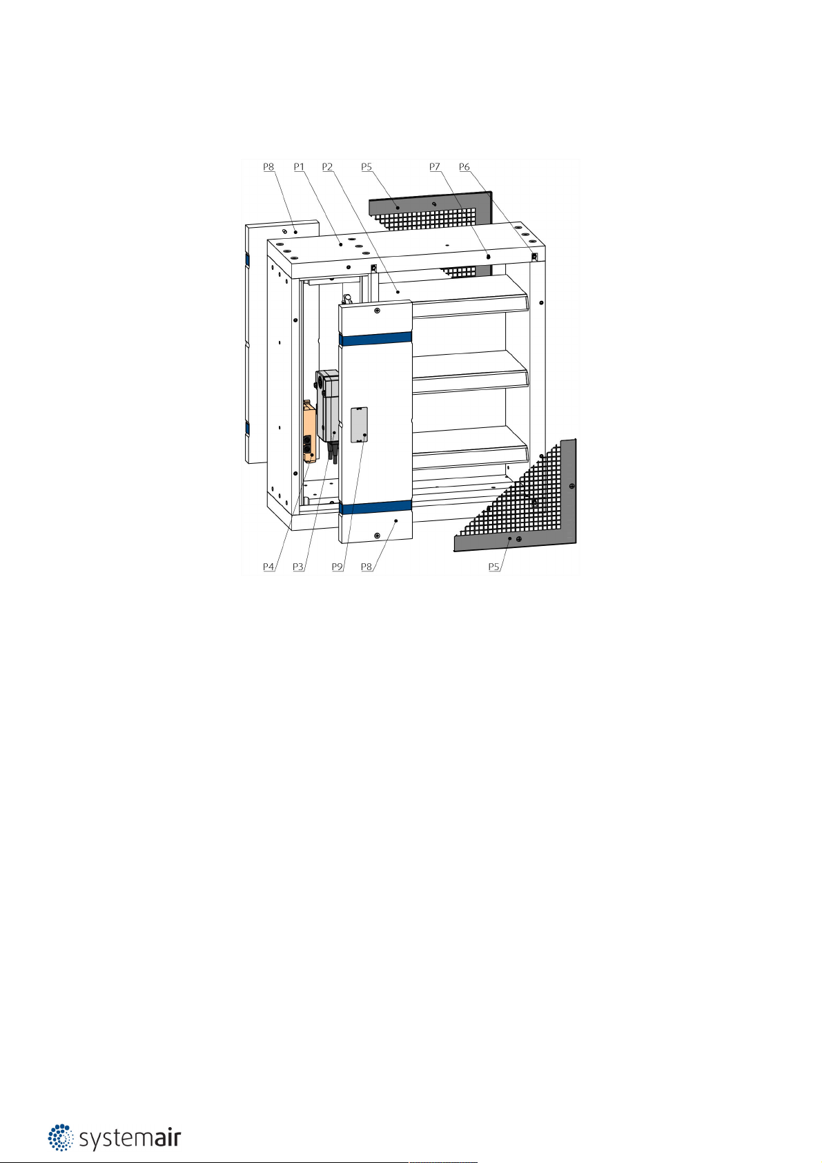
Product Parts
The S-BM2 packaging for selected sizes also includes wooden manipulation jig.
Legend:
P1 - Damper casing
P2 - Damper blade
P3 - Actuator
P4 - Supply and communication unit (BST)
P5 - Sheet metal Grille
P6 - Threaded inserts for duct connection
P7 - Threaded inserts for the grille
P8 - Mechanism cover
P9 - Product label
Page 8

8/108 | S-BM2
Assessed Performance
19 CE 1396
Systemair Production a.s.
90043 Kalinkovo 371, Slovakia
19
1396-CPR-0157
EN 12101-8:2011
Smoke control damper
Multi compartment
S-BM2
Nominal activation conditions/sensitivity
• Manual intervention - passed
Closure/opening during test at correct time and in allowable time
Response delay/closure time - Manual intervention - passed
Operational reliability
10 000 operations: 0° to 90° - passed and 45° to 60° - passed
HOT 400/30 - passed
Fire resistance:
• Integrity E
• EI120(vew-ved-hod-how-i↔o)S1000C
• Damper with vertically oriented blades: EI90(vewi↔o)S1000C
• Insulation I
• Smoke leakage S
• Mechanical stability (under E)
• Maintenance of cross section (under E)
HOT400/30MAmulti
mod
MAmulti
mod
Durability:
• of response delay - Pass
• of operational reliability - Pass
Page 9

9/108 | S-BM2
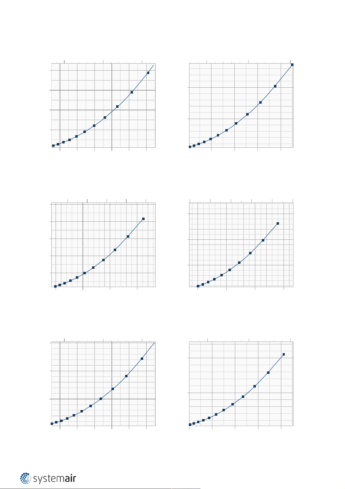
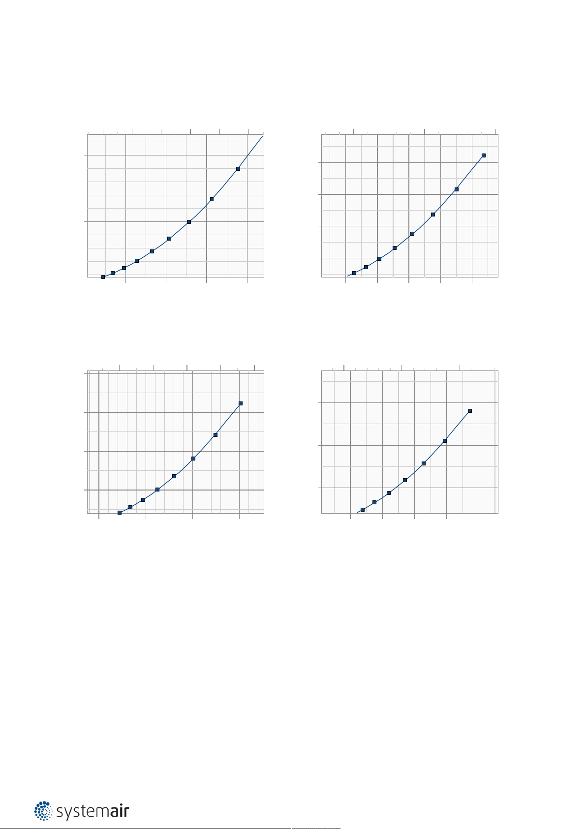
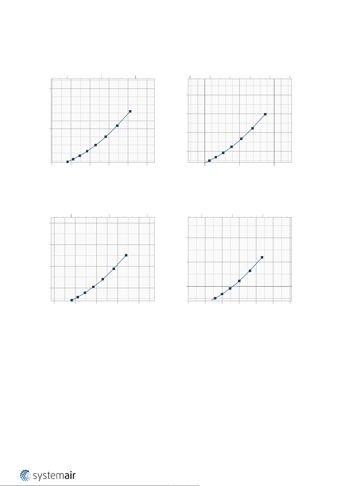
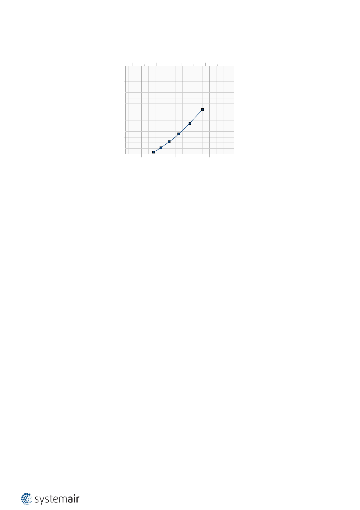
Diagrams of S-BM2 for extract air
Accessories K1-S-BM2 and H1-S-BM2 do not affect the pressure drop and A-weighted total discharged sound power
level.
The pressure drop and A-weighted total discharged sound power level depend on the nominal width and height of the
S-BM2 and air flow volume at different duct pressures.
S-BM2 Grille Types 00, 01, 11, 22
S-BM2-200x425-00-
Pressure drop & sound power level (A-weighted)
250 500 750 l/s
Pa
50
65 dB(A)
60 dB(A)
25
45 dB(A)
40 dB(A)
35 dB(A)
30 dB(A)
800 1200 1600 2000 2400 2800 m³/h
55 dB(A)
50 dB(A)
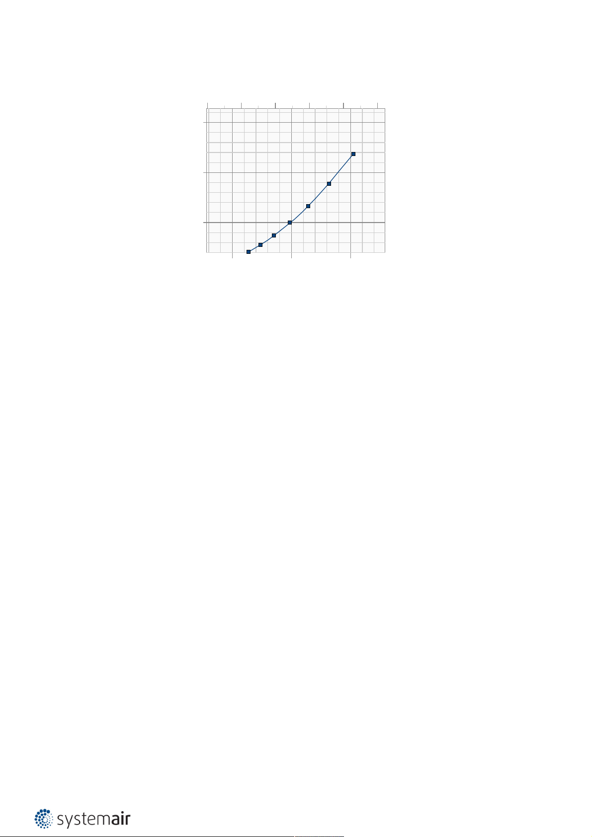
S-BM2-800x825-00-
Pressure drop & sound power level (A-weighted)
Pa
2000 3000 4000 5000 6000 l/s
70 dB(A)
S-BM2-500x625-00-
Pressure drop & sound power level (A-weighted)
800 1200 1600 2000 2400 2800 l/s
Pa
40
30
20
10
40 dB(A)
4000 6000 8000 10000 m³/h
60 dB(A)
55 dB(A)
50 dB(A)
45 dB(A)
70 dB(A)
65 dB(A)
S-BM2-1000x1225-00-
Pressure drop & sound power level (A-weighted)
Pa
4000 6000 8000 10000 12000 l/s
75 dB(A)
30
75 dB(A)
20
10
5000 10000 15000 20000 m³/h
50 dB(A)
45 dB(A)
55 dB(A)
70 dB(A)
65 dB(A)
60 dB(A)
80 dB(A)
20
10
10000 20000 30000 40000 m³/h
65 dB(A)
60 dB(A)
55 dB(A)
50 dB(A)
75 dB(A)
70 dB(A)
Page 10
10/108 | S-BM2
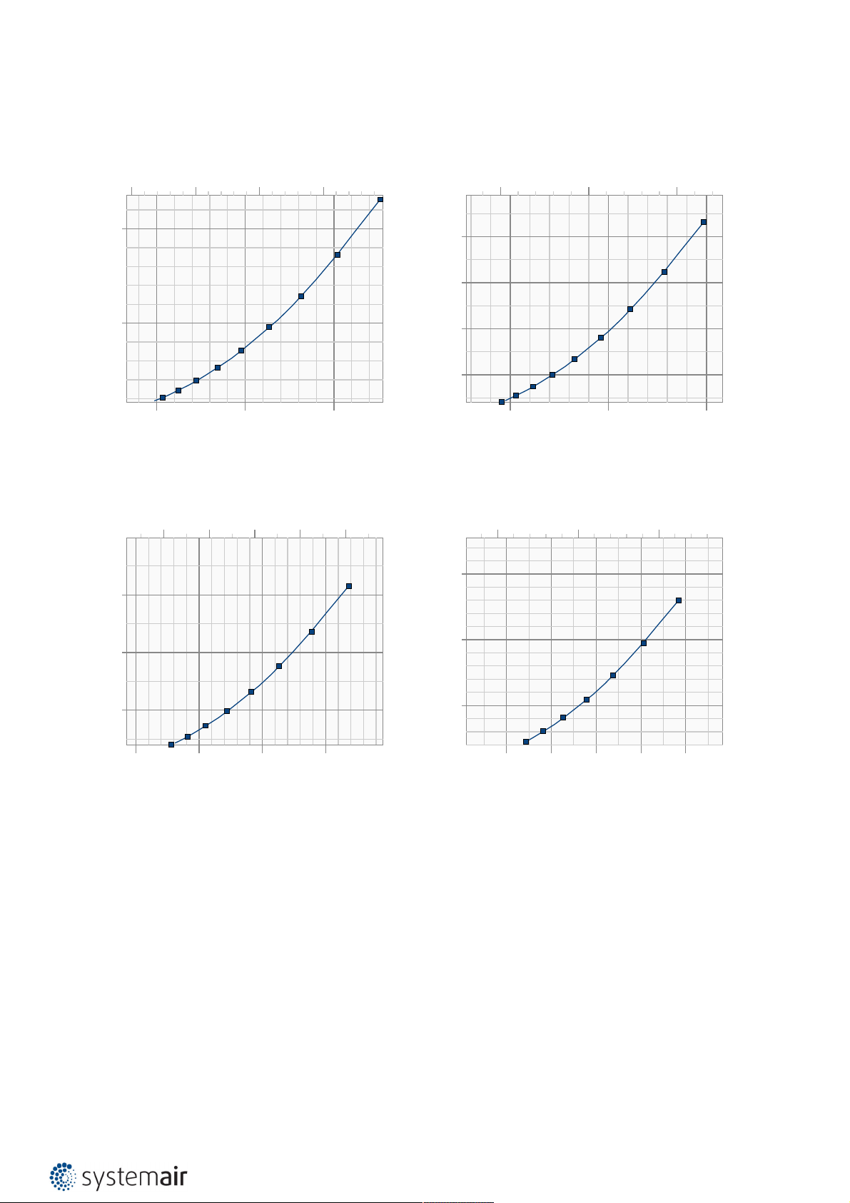
S-BM2-200x425-01-
Pressure drop & sound power level (A-weighted)
Pa
160
120
250 500 750 l/s
70 dB(A)
80
40
30 dB(A)
25 dB(A)
800 1200 1600 2000 2400 2800 m³/h
40 dB(A)
35 dB(A)
45 dB(A)
60 dB(A)
55 dB(A)
50 dB(A)
65 dB(A)
S-BM2-800x825-01-
Pressure drop & sound power level (A-weighted)
Pa
100
80
2000 3000 4000 5000 6000 l/s
75 dB(A)
80 dB(A)
S-BM2-500x625-01-
Pressure drop & sound power level (A-weighted)
Pa
100
50
1000 2000 3000 l/s
75 dB(A)
70 dB(A)
65 dB(A)
60 dB(A)
55 dB(A)
30 dB(A)
35 dB(A)
25 dB(A)
50 dB(A)
45 dB(A)
40 dB(A)
4000 6000 8000 10000 m³/h
S-BM2-1000x1225-01-
Pressure drop & sound power level (A-weighted)
2000 4000 6000 8000 10000 12000 l/s
Pa
75
80 dB(A)
80 dB(A)
60
40
60 dB(A)
20
35 dB(A)
40 dB(A)
30 dB(A)
5000 10000 15000 20000 m³/h
55 dB(A)
50 dB(A)
45 dB(A)
75 dB(A)
70 dB(A)
65 dB(A)
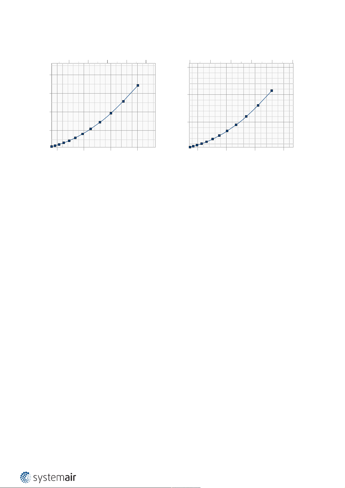
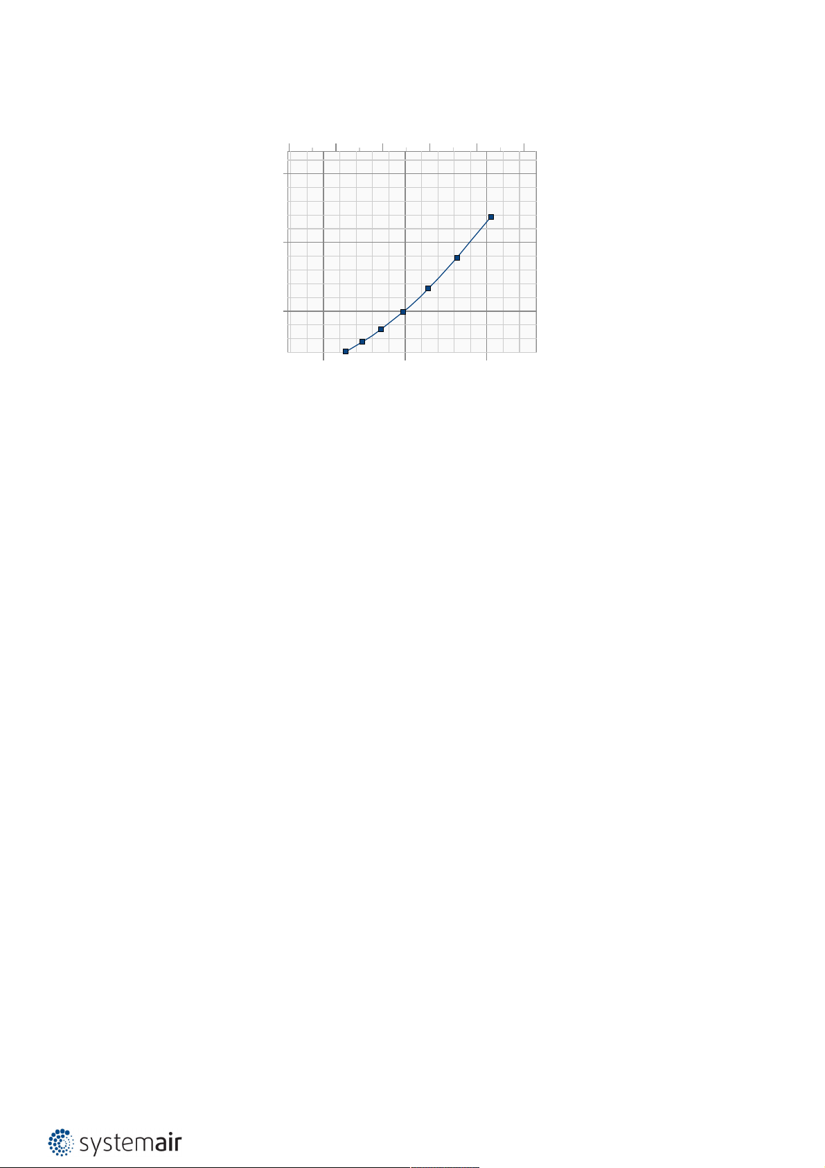
S-BM2-200x425-11-
Pressure drop & sound power level (A-weighted)
Pa
300
200
100
250 500 750 l/s
75 dB(A)
70 dB(A)
65 dB(A)
60 dB(A)
55 dB(A)
30 dB(A)
35 dB(A)
25 dB(A)
800 1200 1600 2000 2400 2800 m³/h
45 dB(A)
40 dB(A)
50 dB(A)
50
25
45 dB(A)
40 dB(A)
35 dB(A)
10000 20000 30000 40000 m³/h
60 dB(A)
55 dB(A)
50 dB(A)
75 dB(A)
70 dB(A)
65 dB(A)
S-BM2-500x625-11-
Pressure drop & sound power level (A-weighted)
Pa
200
100
2000 4000 6000 8000 10000 m³/h
1000 2000 3000 l/s
80 dB(A)
75 dB(A)
70 dB(A)
65 dB(A)
60 dB(A)
55 dB(A)
50 dB(A)
40 dB(A)
35 dB(A)
45 dB(A)
30 dB(A)
25 dB(A)
Page 11
11/108 | S-BM2
S-BM2-800x825-11-
Pressure drop & sound power level (A-weighted)
Pa
160
120
80
40
2000 3000 4000 5000 6000 l/s
80 dB(A)
75 dB(A)
70 dB(A)
65 dB(A)
40 dB(A)
30 dB(A)
45 dB(A)
35 dB(A)
25 dB(A)
5000 10000 15000 20000 m³/h
55 dB(A)
50 dB(A)
60 dB(A)
Legend:
ps (Pa) - Pressure drop
qv (m3^/h), (l/s) - Air flow volume
±Δ (%) - Deviation from measured value
Lwa (dB(A)) - A-weighted total sound power level
v (m/s) - Air face velocity
S-BM2-1000x1225-11-
Pressure drop & sound power level (A-weighted)
2000 4000 6000 8000 10000 12000 l/s
Pa
150
100
70 dB(A)
50
30 dB(A)
25 dB(A)
10000 20000 30000 40000 m³/h
40 dB(A)
35 dB(A)
45 dB(A)
50 dB(A)
60 dB(A)
55 dB(A)
65 dB(A)
80 dB(A)
75 dB(A)
Page 12
12/108 | S-BM2
S-BM2 Grille Types M0, M1 - 2 dampers vertically assembled into battery
S-BM2-200x1530-M0-
Pressure drop & sound power level (A-weighted)
800 1200 1600 2000 2400 2800 l/s
Pa
50
70 dB(A)
55 dB(A)
50 dB(A)
65 dB(A)
60 dB(A)
25
45 dB(A)
40 dB(A)
35 dB(A)
4000 6000 8000 10000 m³/h
S-BM2-600x2130-M0-
Pressure drop & sound power level (A-weighted)
Pa
40
4000 6000 8000 10000 12000 l/s
75 dB(A)
S-BM2-400x1930-M0-
Pressure drop & sound power level (A-weighted)
Pa
40
30
20
10
2500 5000 7500 l/s
75 dB(A)
70 dB(A)
65 dB(A)
60 dB(A)
55 dB(A)
50 dB(A)
45 dB(A)
8000 12000 16000 20000 24000 m³/h
S-BM2-800x2330-M0-
Pressure drop & sound power level (A-weighted)
5000 10000 15000 l/s
Pa
80 dB(A)
30
20
10
50 dB(A)
45 dB(A)
10000 20000 30000 40000 m³/h
60 dB(A)
55 dB(A)
70 dB(A)
65 dB(A)
80 dB(A)
75 dB(A)
30
80 dB(A)
20
10
55 dB(A)
50 dB(A)
20000 30000 40000 50000 60000 m³/h
75 dB(A)
70 dB(A)
65 dB(A)
60 dB(A)
Page 13
13/108 | S-BM2
S-BM2-1000x2530-M0-
Pressure drop & sound power level (A-weighted)
Legend:
4000 8000 12000 16000 20000 24000 l/s
Pa
30
80 dB(A)
20
10
55 dB(A)
50 dB(A)
25000 50000 75000 m³/h
75 dB(A)
70 dB(A)
65 dB(A)
60 dB(A)
ps (Pa) - Pressure drop
qv (m3^/h), (l/s) - Air flow volume
±Δ (%) - Deviation from measured value
Lwa (dB(A)) - A-weighted total sound power level
v (m/s) - Air face velocity
Page 14
14/108 | S-BM2
S-BM2 Grille Types M0, M1 - 2 dampers horizontally assembled into battery
S-BM2-1180x425-M0-
Pressure drop & sound power level (A-weighted)
1000 2000 3000 4000 l/s
Pa
50
75 dB(A)
70 dB(A)
25
45 dB(A)
40 dB(A)
5000 10000 15000 m³/h
65 dB(A)
60 dB(A)
55 dB(A)
50 dB(A)
S-BM2-1680x825-M0-
Pressure drop & sound power level (A-weighted)
Pa
4000 6000 8000 10000 12000 l/s
80 dB(A)
S-BM2-1430x625-M0-
Pressure drop & sound power level (A-weighted)
Pa
2500 5000 7500 l/s
40
30
20
10
45 dB(A)
40 dB(A)
10000 20000 30000 m³/h
55 dB(A)
50 dB(A)
65 dB(A)
60 dB(A)
75 dB(A)
70 dB(A)
S-BM2-1880x1025-M0-
Pressure drop & sound power level (A-weighted)
5000 10000 15000 l/s
Pa
80 dB(A)
30
20
10
50 dB(A)
45 dB(A)
10000 20000 30000 40000 m³/h
60 dB(A)
55 dB(A)
70 dB(A)
65 dB(A)
80 dB(A)
75 dB(A)
30
80 dB(A)
20
10
55 dB(A)
50 dB(A)
20000 30000 40000 50000 60000 m³/h
75 dB(A)
70 dB(A)
65 dB(A)
60 dB(A)
Page 15
15/108 | S-BM2
S-BM2-2080x1225-M0-
Pressure drop & sound power level (A-weighted)
Legend:
4000 8000 12000 16000 20000 24000 l/s
Pa
30
80 dB(A)
20
10
55 dB(A)
50 dB(A)
25000 50000 75000 m³/h
75 dB(A)
70 dB(A)
65 dB(A)
60 dB(A)
ps (Pa) - Pressure drop
qv (m3^/h), (l/s) - Air flow volume
±Δ (%) - Deviation from measured value
Lwa (dB(A)) - A-weighted total sound power level
v (m/s) - Air face velocity
Page 16
16/108 | S-BM2
S-BM2 Grille Types M0, M1 - 4 dampers assembled into battery
S-BM2-1180x1530-M0-
Pressure drop & sound power level (A-weighted)
Pa
50
25
5000 10000 15000 l/s
80 dB(A)
75 dB(A)
70 dB(A)
65 dB(A)
60 dB(A)
55 dB(A)
50 dB(A)
45 dB(A)
10000 20000 30000 40000 50000 60000 m³/h
S-BM2-1680x1930-M0-
Pressure drop & sound power level (A-weighted)
Pa
10000 20000 30000 l/s
S-BM2-1430x1730-M0-
Pressure drop & sound power level (A-weighted)
4000 8000 12000 16000 20000 24000 l/s
Pa
40
30
20
10
25000 50000 75000 m³/h
55 dB(A)
50 dB(A)
70 dB(A)
65 dB(A)
60 dB(A)
80 dB(A)
75 dB(A)
S-BM2-1880x2130-M0-
Pressure drop & sound power level (A-weighted)
10000 20000 30000 l/s
Pa
40
30
80 dB(A)
20
10
55 dB(A)
50 dB(A)
20000 40000 60000 80000 100000 m³/h
65 dB(A)
60 dB(A)
75 dB(A)
70 dB(A)
30
20
10
60 dB(A)
55 dB(A)
20000 40000 60000 80000 100000 120000 140000m³/h
80 dB(A)
75 dB(A)
70 dB(A)
65 dB(A)
Page 17
17/108 | S-BM2
S-BM2-2080x2530-M0-
Pressure drop & sound power level (A-weighted)
10000 20000 30000 40000 50000 l/s
Pa
30
20
10
50000 100000 150000 m³/h
Legend:
ps (Pa) - Pressure drop
qv (m3^/h), (l/s) - Air flow volume
±Δ (%) - Deviation from measured value
Lwa (dB(A)) - A-weighted total sound power level
v (m/s) - Air face velocity
60 dB(A)
55 dB(A)
80 dB(A)
75 dB(A)
70 dB(A)
65 dB(A)
Page 18
18/108 | S-BM2
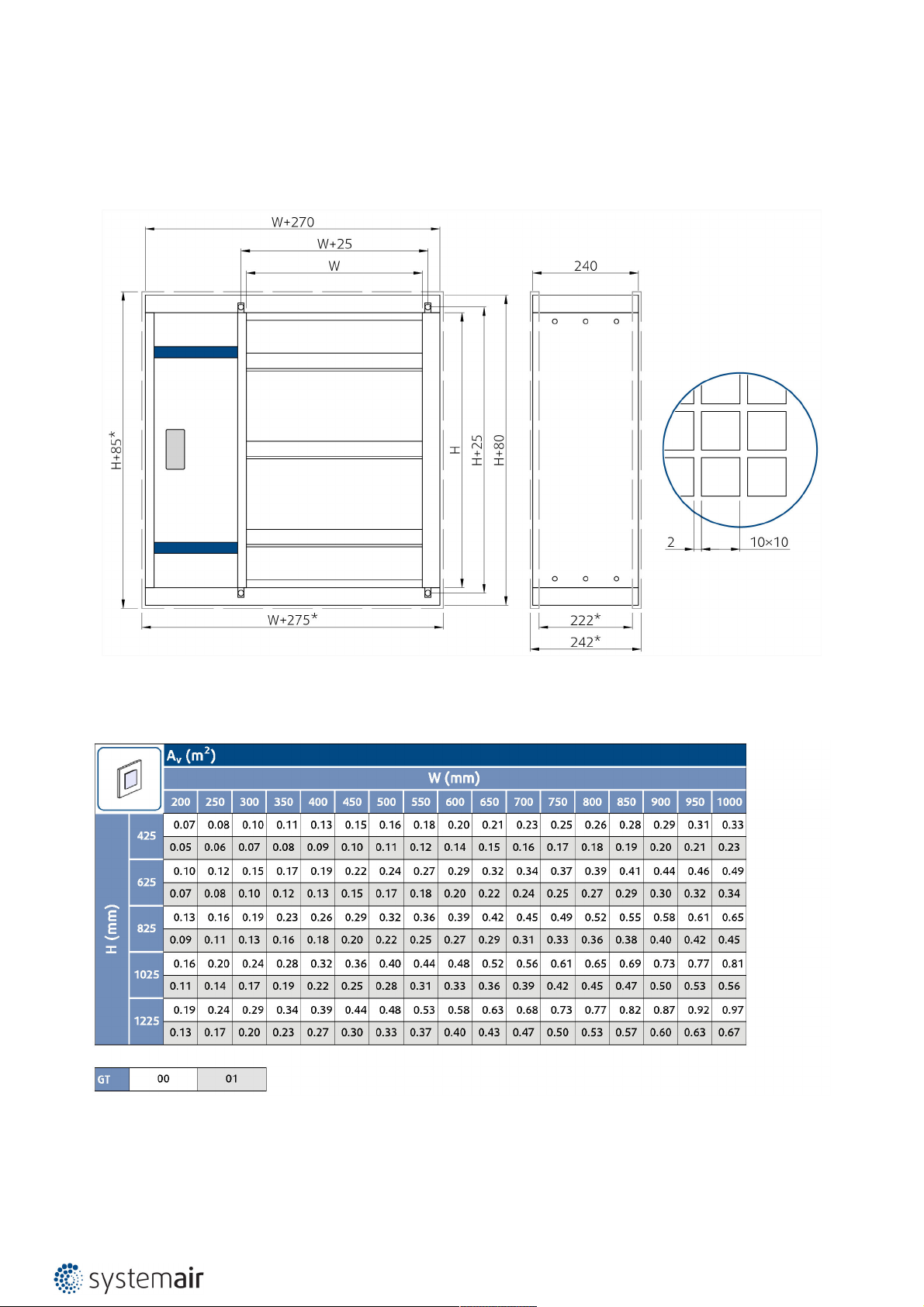
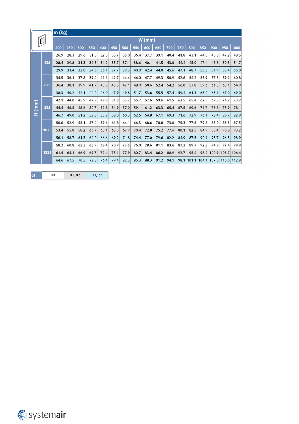
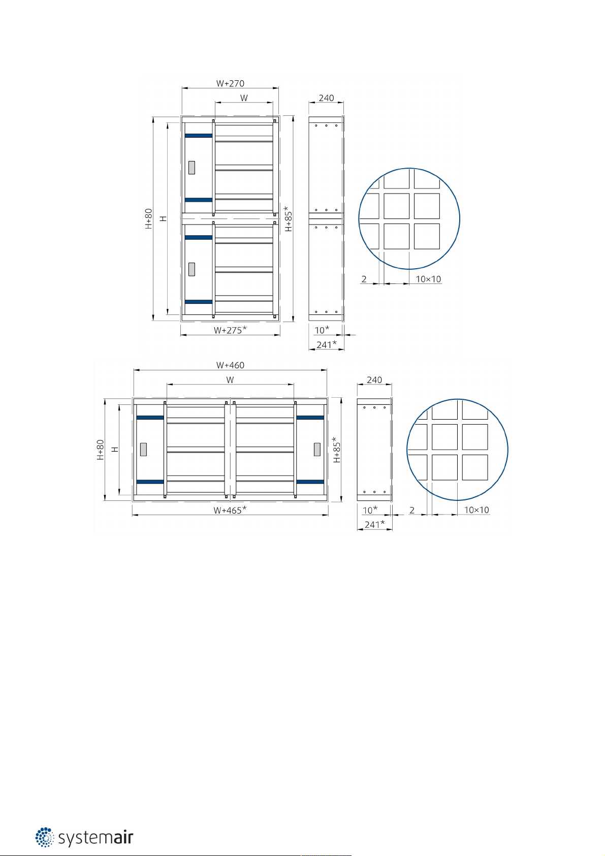
Dimensions & Weights
Dimensions of grille types 00, 01, 11, 02, 22
Note: *Inclusive grille
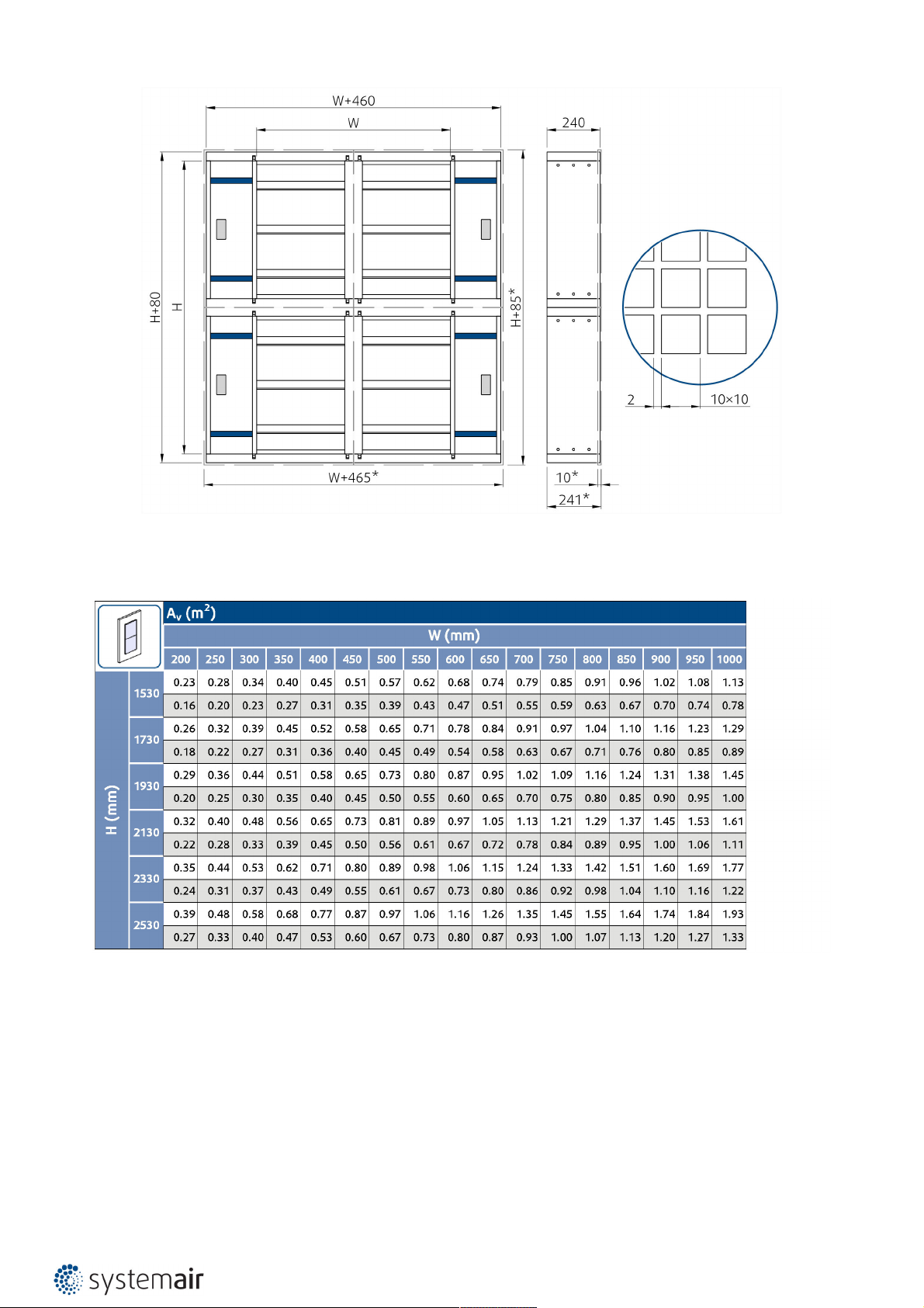
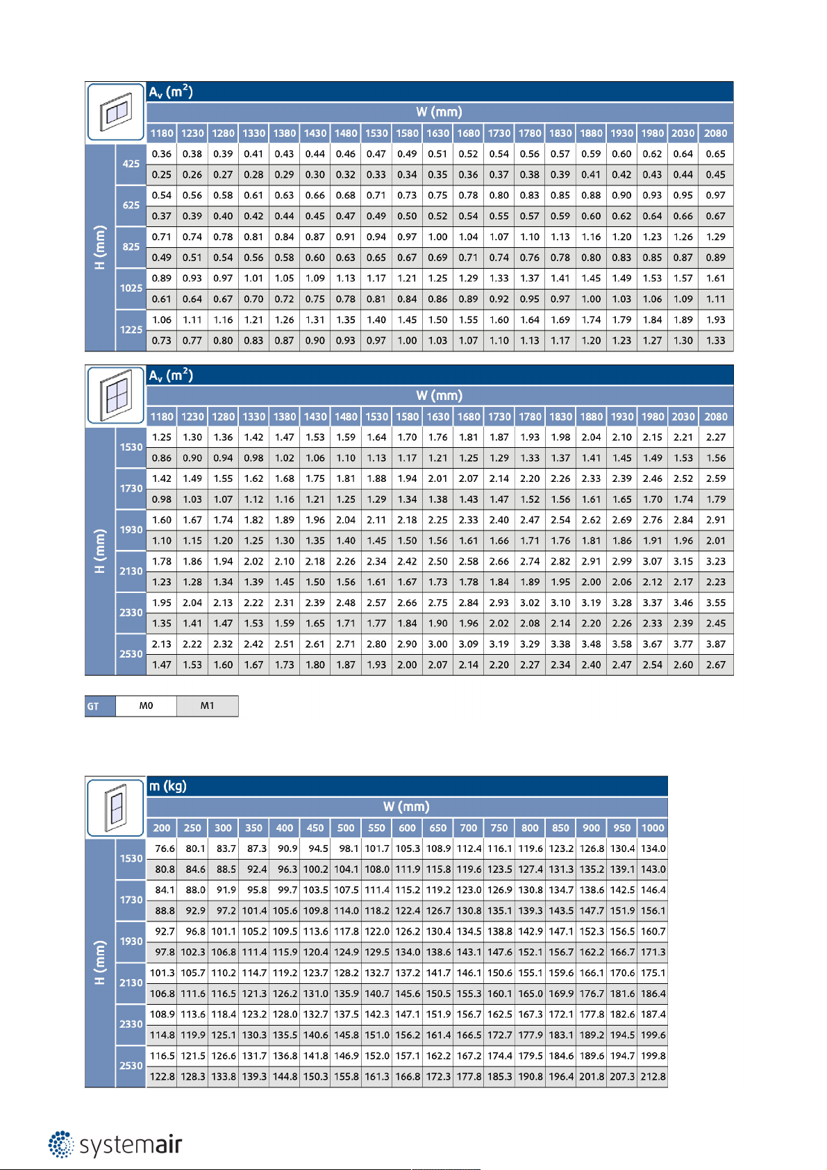
Free area of grille types 00, 01, 11, 02, 22
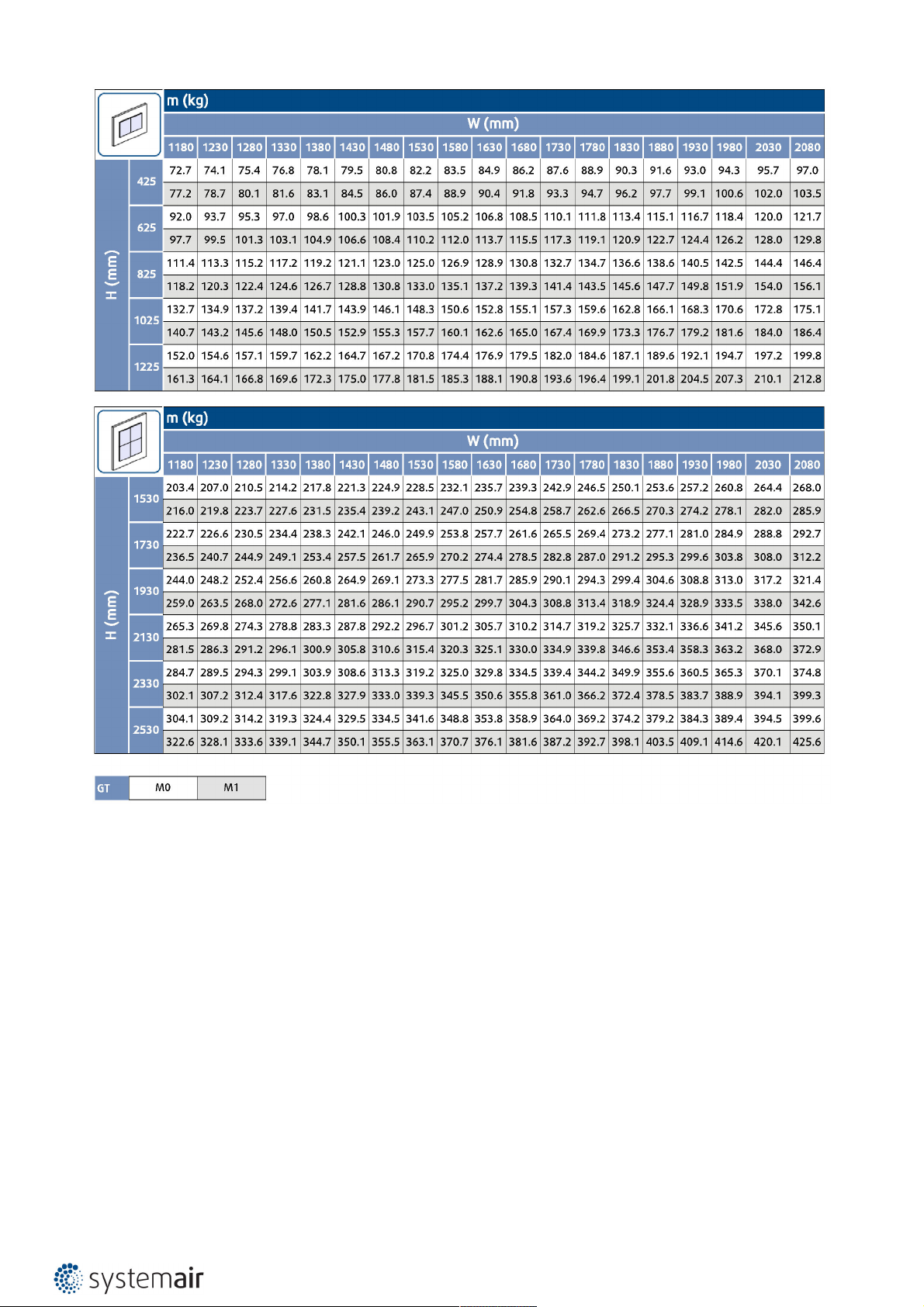
Weights of grille types 00, 01, 11, 02, 22
Page 19
19/108 | S-BM2
Legend:
GT - Grille type
00 - S-BM2 without grille
01, 02 - S-BM2 with one grille
11, 22 - S-BM2 with two grilles
Page 20
20/108 | S-BM2
Dimensions of grille types 00, 01, 11, 02, 22
Page 21
21/108 | S-BM2
Note: *Inclusive grille
Free area of grille type M0, M1 in battery type assembly
Page 22
22/108 | S-BM2
Weights of grille type M0, M1 in battery type assembly
Page 23
23/108 | S-BM2
Legend:
GT - Grille type
M0 - S-BM2 without grille
M1 - S-BM2 with one grille
Page 24
24/108 | S-BM2
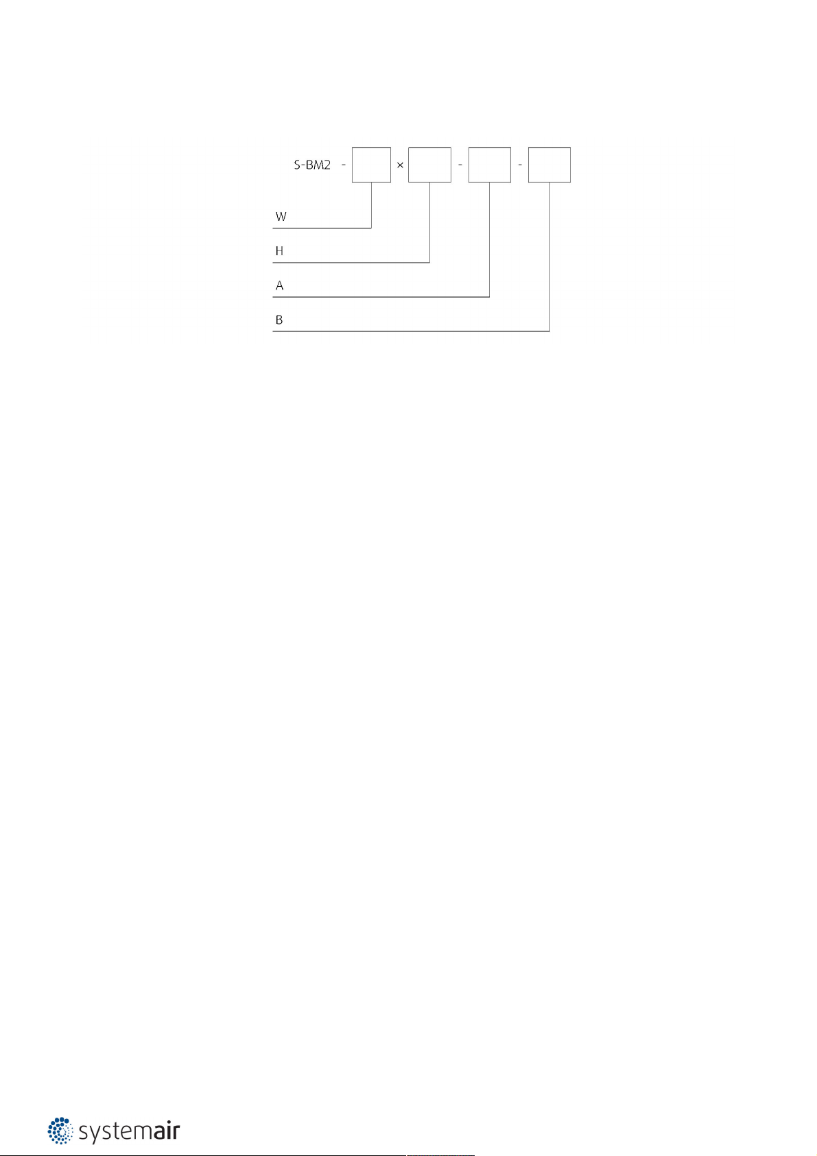
Ordering Codes
W - Width Dimension
200 mm to 1000 mm and battery dimensions 1180 mm to 2080 mm. In step of 50 mm
H - Height Dimensions
425 mm, 625 mm, 825 mm, 1025 mm, 1000 mm and battery dimensions 1530 mm, 1730 mm, 1930 mm, 2130 mm,
2330 mm, 2530 mm.
A - Grille Type
00 - No Grille, duct connectable on both sides
01 - Grille on one side /Zinc/ + connection for duct available on either side
02 - Grille on one side /RAL 9003/ + connection for duct available on either side
11 - Grille on both sides /Zinc/
22 - Grille on both sides /RAL 9003/
M0 - Battery dimensions without Grille
M1 - Battery dimensions with Grille on one side /Zinc/ + connection for duct available on either side
B - Type of Activation
B230 - (230V AC Belimo Actuator)
B24 - (24V AC/DC Belimo Actuator)
B24-W - (24V AC/DC Belimo Actuator & Wire connector for communication unit)
B24-SR - (24V AC/DC Belimo Actuator, modulated 0..10V)
BST - (230V AC Supply comm. unit & 24V AC/DC Belimo Actuator)
Example of the S-BM2 Smoke Control Damper Ordering Code
S-BM2-850×2530-M0-B24-SR
Two Multiblade Smoke control dampers with width of 850 mm and height of 2530 mm, without a grille to be mounted
in battery on top of each other. Activated by a 24 V Modulated Belimo actuator (0..10V).
Page 25
25/108 | S-BM2
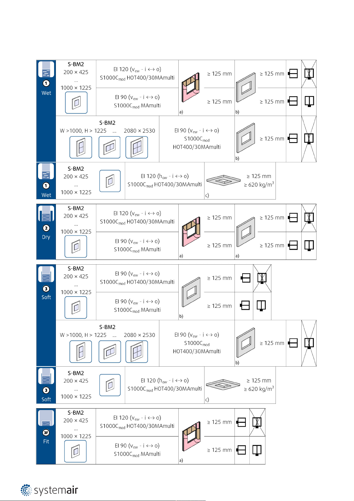
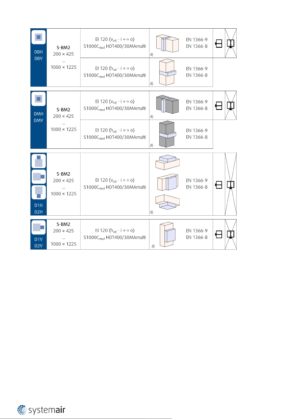
Installation Methods
Page 26
26/108 | S-BM2
Notes:
a) - Flexible (plasterboard) wall
b) - Concrete/masonry/cellular concrete (rigid) wall
c) - Concrete/cellular concrete (rigid) floor/ceiling
d) - Duct per EN 1366-9 or EN 1366-8
vew - Vertical wall placement
how - Horizontal floor/ceiling placement
ved - Horizontal duct, (Vertical wall crossing)
hod - Vertical duct, (Horizontal floor/ceiling crossing)
Installation Rules
• The duct connected to the smoke control damper must be supported or hung in such a way that the damper does not
carry its weight. The damper must not support any part of the surrounding construction or wall which could cause
damage and consequent damper failure.
• Easy access to mechanism and internal parts during inspection must be considered during damper placement.
• According to the standard EN 1366-2, the distance between the smoke control damper bodies must be at least 200
mm.
Page 27

27/108 | S-BM2
• The distance between smoke control damper and the adjacent wall/ceiling and the smoke control damper must be at
least 75 mm.
• When the S-BM2 smoke control damper is installed into a smoke and fire partition structure, it must be placed so that
the damper blades in its closed position are located inside this structure.
• The gap in the installation opening between the smoke control damper and the wall/ceiling can be increased by up to
50% of the gap area or decreased to the smallest amount possible that still provides sufficient space for the
installation of the seal.
• When using non-original grilles, the gap between the damper blade in open position and the self-standing grill, mesh,
louvre must be at least 200 mm according to EN 1366-10.
• The smoke control damper must be earthed after being installed into or onto the duct.
• Lists of all permitted installation methods are provided in User Manual.
Installation, Maintenance & Operation
Some damper parts may have sharp edges – therefore to protect yourself from harm, please use gloves during damper
installation and manipulation. In order to prevent electric shock, fire or any other damage which could result from
incorrect damper usage and operation, it is important to:
1.Ensure that installation is performed by a trained person.
2.Follow the written and depicted instructions provided within Handbook closely.
3.Perform damper inspection in accordance with Handbook.
4.Check the damper’s functionality as per the chapter “Smoke Damper Functionality Check” before you install the fire
damper. This procedure prevents the installation of a damper that has been damaged during transportation or handling.
Information about installation, maintenance and operation is available in the “HandBook_S-BM2” document or more
can be found at design.systemair.com.
Page 28
28/108 | S-BM2
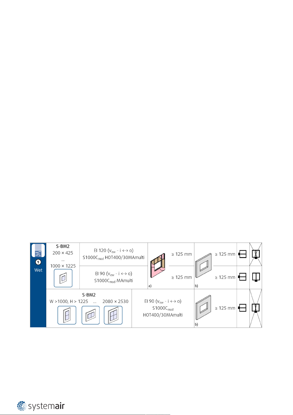
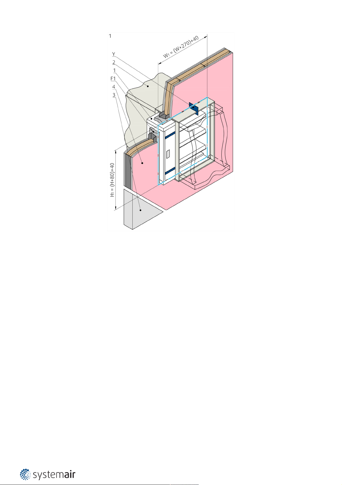
Installation 1. WET - in the Wall
Using Plaster/Mortar/Concrete Filling
1.The supporting construction opening must be prepared as shown on picture. Opening surfaces must be even and
cleaned off. The flexible wall opening must be reinforced as per the standards for plasterboard walls. The opening
dimensions are driven by the nominal dimensions of the damper with added clearance. The opening will be with the
dimensions of W1 and H1.
2.Insert the damper as per the “Manipulation of S-BM2” section into the middle of the opening so that the damper
blade is in the wall. For damper widths greater than 600 mm, it is recommended to use a duct support inside the
damper during installation to avoid any damage caused to the damper housing by the weight of the filling.
For battery assembly:
a. Add the first layer of filling at the bottom of the opening (can be a thin layer)
b. Place the damper(s) on top while fixing them to the sides with screws (F11).
c. Stack the individual dampers on top of each other with caulk (F5) between them and fix together with screws (F12)
and to the wall with screws (F11) as depicted in fixing layout.
3.Fill in the area between the wall and the damper with gypsum plaster or mortar or concrete filling (F1) while paying
attention to prevent the fouling of the damper’s functional parts, which could limit its correct functionality. The best
way is to cover the functional parts during installation. To prevent seepage of the filling material, use of boards is
recommended. First, let the plaster or mortar or concrete filling harden and then perform the next steps.
4.After the filling hardens, remove the duct support from inside of the damper.
5.If needed, uncover and clean the damper after installation.
6.Damper connections to duct and connection with overlap boards must be filled with coating (F5)
7.Check the functionality of the damper.
Installation Distances
According to the EN 1366-2 standard, the minimum distance from the wall or ceiling to the damper body is 75 mm. For
multiple crossings through a fire resistive wall, the minimum distance between two damper bodies is 200 mm. This
applies for distances between the damper body and a nearby foreign object crossing the fire resistive wall.
Notes:
a) - Flexible (plasterboard) wall
b) - Concrete/masonry/cellular concrete (rigid) wall
vew - Vertical wall placement
Page 29
29/108 | S-BM2
Page 30
30/108 | S-BM2
Page 31

31/108 | S-BM2
Page 32

32/108 | S-BM2
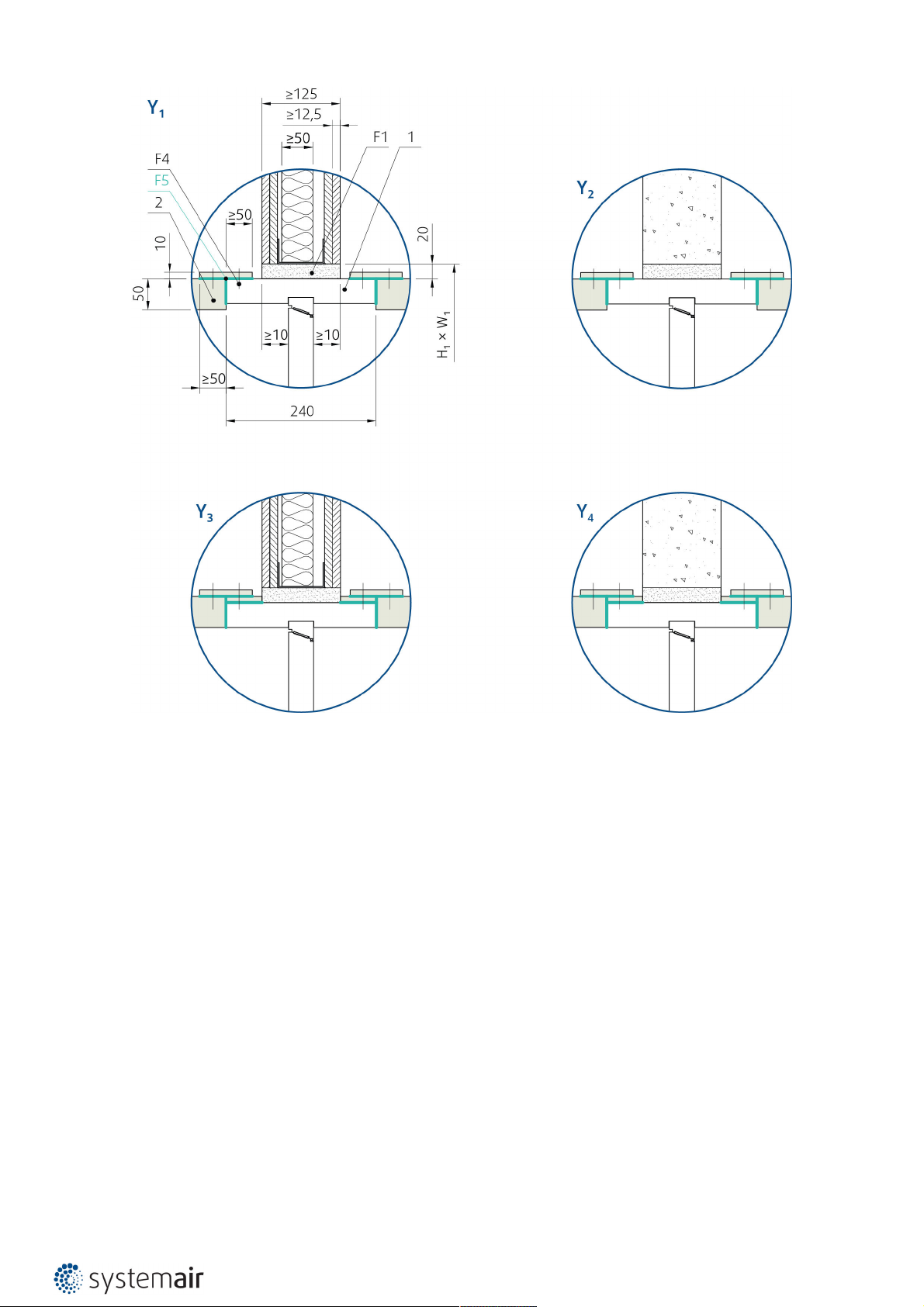
Opening and wall/ceiling preparations
Page 33

33/108 | S-BM2
Damper minimum distances
Page 34

34/108 | S-BM2
Legend for installation 1. WET - in the Wall
1 - Smoke control damper S-BM2
2 - Connected ductwork made of Promatect-L500 boards (min. 500 kg/m3, Promat)
3 - Concrete/masonry/cellular concrete wall or ceiling
4 - Flexible (plasterboard) wall
4a - 2 layers of plasterboard fireproof plate type F, EN 520
4b - Vertical CW – profiles
4c - Horizontal UW – profiles
4d - Mineral wool; thickness/cubic density see picture.
5 - Grille
7 - Connected sheet metal ductwork tested according to EN 1366-8 or EN 1366-9
F1 - Plaster/mortar/concrete filling
F4 - Nails or pins per ductwork manufacturer instructions
F5 - Fire resistive coating Promat K84 (Promat)
F8 - Screw M8×35, maximum fixing torque is 8 Nm ...12 Nm
F11 - Screw M5 × ≥100 mm to concrete/Screw M4,5 × ≥120 mm to cellular concrete
F12 - Screw M5 × 60-70 mm (e.g. DIN 7982)
a) - If connected to a duct, please follow the instructions duct manufacturer (maximum duct size width × height)
b) - Internal stiffener is driven by the duct manufacturer instructions (Make sure to add where needed)
Y - Cutting plane
Page 35

35/108 | S-BM2
Battery Installation, Grille type M0, M1
Page 36

36/108 | S-BM2
Page 37

37/108 | S-BM2
Fixing layout for battery installations
Page 38

38/108 | S-BM2
Opening and wall/ceiling preparations
Damper minimum distances
Page 39

39/108 | S-BM2
Legend for installation 1. WET - in the Wall assembled in battery
1 - Smoke control damper S-BM2
2 - Connected ductwork made of Promatect-L500 boards (min. 500 kg/m3, Promat)
3 - Concrete/masonry/cellular concrete wall or ceiling
5 - Grille
7 - Connected sheet metal ductwork tested according to EN 1366-8 or EN 1366-9
F1 - Plaster/mortar/concrete filling
F4 - Nails or pins per ductwork manufacturer instructions
F5 - Fire resistive coating Promat K84 (Promat)
F8 - Screw M8×35, maximum fixing torque is 8 Nm ...12 Nm
F11 - Screw M5 × ≥100 mm to concrete/Screw M4,5 × ≥120 mm to cellular concrete
F12 - Screw M5 × 60-70 mm (e.g. DIN 7982)
a) - If connected to a duct, please follow the instructions duct manufacturer (maximum duct size width × height)
b) - Internal stiffener is driven by the duct manufacturer instructions (Make sure to add where needed)
Y - Cutting plane
Page 40

40/108 | S-BM2
Installation 1. WET - in the Ceiling
Using Plaster/Mortar/Concrete Filling
1.The supporting construction opening must be prepared as shown on picture. Opening surfaces must be even and
cleaned off. The opening dimensions are driven by the nominal dimensions of the damper with added clearance. The
opening will be with the dimensions of W1 and H1.
2.Mount the hanger plates (A2) on the damper body only on the side which will be flush with the upper ceiling surface.
3.Insert the damper into the middle of the opening so that the damper blade is in the ceiling. On the previously
mounted hanger plates and if there on the prepared connecting duct.
4.Place the hanger plates (A2) flush with the damper body and the supporting construction from below.
5.From both sides of the supporting construction, fix the hanger plates to the damper and the supporting construction
with at least 6 screws per each hanger.
6.Fill in the area between the ceiling and the damper with gypsum plaster or mortar or concrete filling (F1) while
paying attention to prevent the fouling of the damper’s functional parts, which could limit its correct functionality.
The best way is to cover the functional parts during installation. To prevent seepage of the filling material, use of
boards is recommended.
7.First, let the plaster or mortar or concrete filling harden before removing the supporting fixtures.
8.If needed, uncover and clean the damper after installation.
9.Damper connections to duct and connection with overlap boards must be filled with coating (F5).
10.Check the functionality of the damper.
Installation Distances
According to the EN 1366-2 standard, the minimum distance from the wall or ceiling to the damper body is 75 mm. For
multiple crossings through a fire resistive wall, the minimum distance between two damper bodies is 200 mm. This
applies for distances between the damper body and a nearby foreign object crossing the fire resistive wall.
Notes:
c) - Concrete/cellular concrete (rigid) floor/ceiling
how - Horizontal floor/ceiling placement
Page 41

41/108 | S-BM2
Page 42

42/108 | S-BM2
Page 43

43/108 | S-BM2
Page 44

44/108 | S-BM2
Opening and wall/ceiling preparations
Damper minimum distances
Page 45

45/108 | S-BM2
Legend for installation 1. WET - in the Ceiling
1 - Smoke control damper S-BM2
2 - Connected ductwork made of Promatect-L500 boards (min. 500 kg/m3, Promat)
3 - Concrete/masonry/cellular concrete wall or ceiling
4 - Flexible (plasterboard) wall
4a - 2 layers of plasterboard fireproof plate type F, EN 520
4b - Vertical CW – profiles
4c - Horizontal UW – profiles
4d - Mineral wool; thickness/cubic density see picture.
5 - Grille
7 - Connected sheet metal ductwork tested according to EN 1366-8 or EN 1366-9
A2 - Hanger accessory H1-S-BM2 - can be made on site using 3 mm sheet metal plate.
• For sizes W<550 & H<425 use 1 piece on each damper edge. Total 4 pcs for each side of wall.
• For sizes bigger than W=550 & H=425 use 2 piece on each damper edge. Total 8 pcs for each side of wall.
F1 - Plaster/mortar/concrete filling
F4 - Nails or pins per ductwork manufacturer instructions
F5 - Fire resistive coating Promat K84 (Promat)
F8 - Screw M8×35, maximum fixing torque is 8 Nm ...12 Nm
F11 - Screw M5 × ≥100 mm to concrete/Screw M4,5 × ≥120 mm to cellular concrete
F12 - Screw M5 × 60-70 mm (e.g. DIN 7982)
a) - If connected to a duct, please follow the instructions duct manufacturer (maximum duct size width × height)
b) - Internal stiffener is driven by the duct manufacturer instructions (Make sure to add where needed)
Y - Cutting plane
Page 46

46/108 | S-BM2
Installation 2. DRY
Using Mineral Wool and Cover Boards
1.The supporting construction opening must be prepared as shown on picture. Opening surfaces must be even and
cleaned off. The flexible wall opening must be reinforced as per the standards for plasterboard walls. The opening
dimensions are driven by the nominal dimensions of the damper with added clearance. The opening will be with the
dimensions of W1 and H1.
2.Insert the damper as per the “Manipulation of S-BM2” section into the middle of the opening so that the damper
blade is in the wall. For damper widths greater than 600 mm, it is recommended to use a duct support inside the
damper during installation to avoid any damage caused to the damper housing by the weight of the filling.
3.Fill in the area between the wall and the damper with mineral wool (F2) with a density of at least 100 kg/m3
thoroughly but in such a way that will not deform the duct/damper.
4.Cover the gap/filling between the damper and the mounting opening with gypsum boards (6) with applied coating
(F7) and fix them with screws (F6) to the wall.
5.Damper connections to duct and connection with overlap boards must be filled with coating (F5).
6.Check the functionality of the damper.
Installation Distances
According to the EN 1366-2 standard, the minimum distance from the wall or ceiling to the damper body is 75 mm. For
multiple crossings through a fire resistive wall, the minimum distance between two damper bodies is 200 mm. This
applies for distances between the damper body and a nearby foreign object crossing the fire resistive wall.
Notes:
a) - Flexible (plasterboard) wall
b) - Concrete/masonry/cellular concrete (rigid) wall
vew - Vertical wall placement
Page 47

47/108 | S-BM2
Page 48

48/108 | S-BM2
Page 49

49/108 | S-BM2
Page 50

50/108 | S-BM2
Opening and wall/ceiling preparations
Page 51

51/108 | S-BM2
Damper minimum distances
Page 52

52/108 | S-BM2
Legend for Installation 2. DRY
1 - Smoke control damper S-BM2
2 - Connected ductwork made of Promatect-L500 boards (min. 500 kg/m3, Promat)
3 - Concrete/masonry/cellular concrete wall or ceiling
4 - Flexible (plasterboard) wall
4a - 2 layers of plasterboard fireproof plate type F, EN 520
4b - Vertical CW – profiles
4c - Horizontal UW – profiles
4d - Mineral wool; thickness/cubic density see picture.
5 - Grille
6 - Gypsum boards
F2 - Mineral wool filling (min. 100 kg/m³)
F4 - Nails or pins per ductwork manufacturer instructions
F5 - Fire resistive coating Promat K84 (Promat)
F6 - Screws for fixing gypsum boards to: flexible wall (TN 3,5×35)/rigid wall (HUS-CR 8×65)
F7 - Putty for gypsum boards, e.g. Rigips Super
Y - Cutting plane
Page 53

53/108 | S-BM2
Installation 3. SOFT - in the Wall
Using Mineral Wool filing
1.The supporting construction opening must be prepared as shown on picture. Opening surfaces must be even and
cleaned off. The flexible wall opening must be reinforced as per the standards for plasterboard walls. The opening
dimensions are driven by the nominal dimensions of the damper with added clearance. The opening will be with the
dimensions of W1 and H1.
2.Insert the damper as per the “Manipulation of S-BM2” section into the middle of the opening so that the damper
blade is in the wall. For damper widths greater than 600 mm, it is recommended to use a duct support inside the
damper during installation to avoid any damage caused to the damper housing by the weight of the filling.
For battery assembly:
a .Add the first layer of filling at the bottom of the opening - can be very thin.
b. Place the damper(s) on top while fixing them to the sides with screws (F11).
c. Stack the individual dampers on top of each other with caulk (F5) between them and fix together with screws (F12)
and to the wall with screws (F11) as depicted in fixing layout.
3.Fill in the area between the wall and the damper with mineral wool (F2) with a density of at least 100 kg/m3
thoroughly but in such a way that will not deform the duct/damper.
4.All the gaps around the filling and ceiling surface area at least 40 mm from the damper body must be covered by fire
resistive coating (F10).
5.Damper connections to duct and connection with overlap boards must be filled with coating (F5).
6.Check the functionality of the damper.
Installation Distances
According to the EN 1366-2 standard, the minimum distance from the wall or ceiling to the damper body is 75 mm. For
multiple crossings through a fire resistive wall, the minimum distance between two damper bodies is 200 mm. This
applies for distances between the damper body and a nearby foreign object crossing the fire resistive wall.
Notes:
b) - Concrete/masonry/cellular concrete (rigid) wall
vew - Vertical wall placement
Page 54

54/108 | S-BM2
Page 55

55/108 | S-BM2
Page 56

56/108 | S-BM2
Opening and wall/ceiling preparations
Damper minimum distances
Page 57

57/108 | S-BM2
Legend for installation 3. SOFT - in the Wall
1 - Smoke control damper S-BM2
2 - Connected ductwork made of Promatect-L500 boards (min. 500 kg/m3, Promat)
3 - Concrete/masonry/cellular concrete wall or ceiling
4 - Flexible (plasterboard) wall
4a - 2 layers of plasterboard fireproof plate type F, EN 520
4b - Vertical CW – profiles
4c - Horizontal UW – profiles
4d - Mineral wool; thickness/cubic density see picture.
5 - Grille
7 - Connected sheet metal ductwork tested according to EN 1366-8 or EN 1366-9
F2 - Mineral wool filling (min. 100 kg/m³)
F4 - Nails or pins per ductwork manufacturer instructions
F5 - Fire resistive coating Promat K84 (Promat)
F8 - Screw M8×35, maximum fixing torque is 8 Nm ...12 Nm
F10 - Fireproof coating HILTY CSF-CT min. 2 mm
F11 - Screw M5 × ≥100 mm to concrete/Screw M4,5 × ≥120 mm to cellular concrete
F12 - Screw M5 × 60-70 mm (e.g. DIN 7982)
a) - If connected to a duct, please follow the instructions duct manufacturer (maximum duct size width × height)
b) - Internal stiffener is driven by the duct manufacturer instructions (Make sure to add where needed)
Y - Cutting plane
Page 58

58/108 | S-BM2
Battery Installation, Grille type M0, M1
Page 59

59/108 | S-BM2
Page 60

60/108 | S-BM2
Fixing layout for battery installations
Page 61

61/108 | S-BM2
Opening and wall/ceiling preparations
Damper minimum distances
Page 62

62/108 | S-BM2
Legend for installation 3. SOFT - in the Wall assembled in battery
1 - Smoke control damper S-BM2
2 - Connected ductwork made of Promatect-L500 boards (min. 500 kg/m3, Promat)
3 - Concrete/masonry/cellular concrete wall or ceiling
4 - Flexible (plasterboard) wall
4a - 2 layers of plasterboard fireproof plate type F, EN 520
4b - Vertical CW – profiles
4c - Horizontal UW – profiles
4d - Mineral wool; thickness/cubic density see picture.
5 - Grille
7 - Connected sheet metal ductwork tested according to EN 1366-8 or EN 1366-9
F2 - Mineral wool filling (min. 100 kg/m³)
F4 - Nails or pins per ductwork manufacturer instructions
F5 - Fire resistive coating Promat K84 (Promat)
F8 - Screw M8×35, maximum fixing torque is 8 Nm ...12 Nm
F10 - Fireproof coating HILTY CSF-CT min. 2 mm
F11 - Screw M5 × ≥100 mm to concrete/Screw M4,5 × ≥120 mm to cellular concrete
F12 - Screw M5 × 60-70 mm (e.g. DIN 7982)
a) - If connected to a duct, please follow the instructions duct manufacturer (maximum duct size width × height)
b) - Internal stiffener is driven by the duct manufacturer instructions (Make sure to add where needed)
Y - Cutting plane
Page 63

63/108 | S-BM2
Installation 3. SOFT - in the Ceiling
Using Mineral Wool filing
1.The supporting construction opening must be prepared as shown on picture. Opening surfaces must be even and
cleaned off. The opening dimensions are driven by the nominal dimensions of the damper with added clearance. The
opening will be with the dimensions of W1 and H1.
2.Mount the hanger plates (A2) on the damper body only on the side which will be flush with the upper ceiling surface.
3.Insert the damper into the middle of the opening so that the damper blade is in the ceiling. On the previously
mounted hanger plates and if there on the prepared connecting duct.
4.Place the hanger plates (A2) flush with the damper body and the supporting construction from below.
5.From both sides of the supporting construction, fix the hanger plates the supporting construction and to the damper
with at least 6 screws per each hanger.
6.Fill in the area between the ceiling and the damper with mineral wool (F2) with a density of at least 100 kg/m3
thoroughly but in such a way that will not deform the body of the damper.
7.All the gaps around the filling and ceiling surface area at least 100 mm from the damper body must be covered by
fire resistive coating (F10).
8.Damper connections to duct and connection with overlap boards must be filled with coating (F5).
9.Check the functionality of the damper.
Installation Distances
According to the EN 1366-2 standard, the minimum distance from the wall or ceiling to the damper body is 75 mm. For
multiple crossings through a fire resistive wall, the minimum distance between two damper bodies is 200 mm. This
applies for distances between the damper body and a nearby foreign object crossing the fire resistive wall.
Notes:
c) - Concrete/cellular concrete (rigid) floor/ceiling
how - Horizontal floor/ceiling placement
Page 64

64/108 | S-BM2
Page 65

65/108 | S-BM2
Page 66

66/108 | S-BM2
Page 67

67/108 | S-BM2
Opening and wall/ceiling preparations
Damper minimum distances
Page 68

68/108 | S-BM2
Legend for installation 3. SOFT - in the Ceiling
1 - Smoke control damper S-BM2
2 - Connected ductwork made of Promatect-L500 boards (min. 500 kg/m3, Promat)
3 - Concrete/masonry/cellular concrete wall or ceiling
4 - Flexible (plasterboard) wall
4a - 2 layers of plasterboard fireproof plate type F, EN 520
4b - Vertical CW – profiles
4c - Horizontal UW – profiles
4d - Mineral wool; thickness/cubic density see picture.
5 - Grille
7 - Connected sheet metal ductwork tested according to EN 1366-8 or EN 1366-9
A2 - Hanger accessory H1-S-BM2 - can be made on site using 3 mm sheet metal plate.
• For sizes W<550 & H<425 use 1 piece on each damper edge. Total 4 pcs for each side of wall.
• For sizes bigger than W=550 & H=425 use 2 pieces on each damper edge. Total 8 pcs for each side of wall.
F2 - Mineral wool filling (min. 100 kg/m³)
F4 - Nails or pins per ductwork manufacturer instructions
F5 - Fire resistive coating Promat K84 (Promat)
F8 - Screw M8×35, maximum fixing torque is 8 Nm ...12 Nm
F10 - Fireproof coating HILTY CSF-CT min. 2 mm
F11 - Screw M5 × ≥100 mm to concrete/Screw M4,5 × ≥120 mm to cellular concrete
F12 - Screw M5 × 60-70 mm (e.g. DIN 7982)
a) - If connected to a duct, please follow the instructions duct manufacturer (maximum duct size width × height)
b) - Internal stiffener is driven by the duct manufacturer instructions (Make sure to add where needed)
Y - Cutting plane
Page 69

69/108 | S-BM2
Installation 3F. Fit
Wall build around the damper, filled with mineral wool
With this installation the wall is closed off by gypsum board layers around the damper after the insertion of the damper.
1.The opening dimensions are driven by the nominal dimensions of the damper with added clearance. The opening will
be with the dimensions of W1 and H1.
2.Mount the bottom horizontal metal profile (4c) 20 mm below the destined bottom damper edge.
3.Place mineral wool segment (F2) with height 20 mm on one vertical profile and the bottom profile.
4.Place the damper as per the “Manipulation of S-BM2” section onto the sides gently pressing the mineral wool
segments.
Make sure the damper blades in closed position will be situated above the horizontal metal profile.
5.Fix the damper with screws (F9) through the metal sides fitted with mineral wool segments.
6.Fill in the area between the metal profile (4b) on the remaining side with mineral wool segment (F2).
7.Place a mineral wool segment (F2) on top of the damper and cover it with horizontal metal profile (4c).
8.Fix the profile with screws (F9) through the mineral wool segment to the damper and then on both sides to the wall
vertical profiles.
9.Cover both sides with 2 layers of gypsum boards (4a) on each side without a gap between the damper and the
boards.
10.Damper connections to duct and connection with overlap boards must be filled with coating (F5).
11.Check the functionality of the damper.
Installation Distances
According to the EN 1366-2 standard, the minimum distance from the wall or ceiling to the damper body is 75 mm. For
multiple crossings through a fire resistive wall, the minimum distance between two damper bodies is 200 mm. This
applies for distances between the damper body and a nearby foreign object crossing the fire resistive wall.
Notes:
a) - Flexible (plasterboard) wall
vew - Vertical wall placement
Page 70

70/108 | S-BM2
Page 71

71/108 | S-BM2
Page 72

72/108 | S-BM2
Opening and wall/ceiling preparations
Page 73

73/108 | S-BM2
Damper minimum distances
Legend for installation 3F. Fit
1 - Smoke control damper S-BM2
2 - Connected ductwork made of Promatect-L500 boards (min. 500 kg/m3, Promat)
3 - Concrete/masonry/cellular concrete wall or ceiling
4 - Flexible (plasterboard) wall
4a - 2 layers of plasterboard fireproof plate type F, EN 520
4b - Vertical CW – profiles
4c - Horizontal UW – profiles
4d - Mineral wool; thickness/cubic density see picture.
5 - Grille
F2 - Mineral wool filling (min. 100 kg/m³)
F4 - Nails or pins per ductwork manufacturer instructions
F5 - Fire resistive coating Promat K84 (Promat)
F9 - Self-tapping screw size 4, length 45 mm (e.g. DIN 7981 C-H)
Y - Cutting plane
Page 74

74/108 | S-BM2
Installation DBH, DBV - in the Board Duct
S-BM2 smoke control damper can be installed on “single” (tested according to EN 1366-9) or “multi” (tested according
to EN 1366-8) ductwork. This section does not depict duct hanger rules as those are dependent on the weight of the
duct itself and must be statically approved. Smoke control dampers must be suspended from solid ceiling slabs using
adequately sized threaded rods. When using anchors in the ceiling, use fire rated anchor (with suitable fire rating
certificate).
1.Prepare the duct connection or opening, clean and flatten the connecting surface.
2.Apply fire resistive coat (F5) on the connection surfaces.
3.Place the damper against the ductwork connection surfaces.
For vertical duct orientation: a. Fix the hangers (A2) to the damper body or on the accessory (A1) or cover boards (8).
b. If the duct is not yet installed place the damper with the hangers (A2) onto the load bearing hanger profile.
4.From boards (8) create collars and overlap the connection.
5.Fix the collar covering to the damper and ductwork with nails or pins as per duct system manufacturer instructions.
IMPORTANT
• The suspension of the damper must be loaded only with the weight of the damper.
• Suspension systems longer than 1,5 m require fire-resistant insulation.
• The interior of the S-BM2 smoke control damper must remain accessible for maintenance, it may be necessary to
create additional inspection panels in the connecting ducts.
• The fire resistivity of S-BM2 smoke control damper must be decreased to the duct performance.
• The maximum resistivity for in duct installation is EI120S with pressure level 2 (-1000 Pa … 300 Pa)
Installation Distances
According to the EN 1366-2 standard, the minimum distance from the wall or ceiling to the damper body is 75 mm. For
multiple crossings through a fire resistive wall, the minimum distance between two damper bodies is 200 mm. This
applies for distances between the damper body and a nearby foreign object crossing the fire resistive wall/duct.
Notes:
d) - Duct per EN 1366-9 or EN 1366-8
ved - Horizontal duct, (Vertical wall crossing)
hod - Vertical duct, (Horizontal floor/ceiling crossing)
Page 75

75/108 | S-BM2
Page 76

76/108 | S-BM2
Damper minimum distances
Legend for installation DBH, DBV - in the Board Duct
1 - Smoke control damper S-BM2
2 - Connected ductwork made of Promatect-L500 boards (min. 500 kg/m3, Promat)
8 - Cover plate made of Promatect (min. 500 kg/m3, Promat)
F4 - Nails or pins per ductwork manufacturer instructions
F5 - Fire resistive coating Promat K84 (Promat)
A1 - Accessory K1-S-BM2-W×H (size of damper: W = nominal width; H = nominal height)
A2 - Hanger accessory H1-S-BM2 - can be made on site using 3 mm sheet metal plate.
• For sizes W<550 or H<425 use 2 pieces on two damper edge. Total 4 pcs.
• For sizes bigger than W=550 or H=425 use 3 pieces on each damper edge. Total 6 pcs.
X, Y - Cutting planes
Page 77

77/108 | S-BM2
Installation DMH, DMV - in the Metal Duct
S-BM2 smoke control damper can be installed on “single” (tested according to EN 1366-9) or “multi” (tested according
to EN 1366-8) ductwork. This section does not depict duct hanger rules as those are dependent on the weight of the
duct itself and must be statically approved. Smoke control dampers must be suspended from solid ceiling slabs using
adequately sized threaded rods. When using anchors in the ceiling, use fire rated anchor (with suitable fire rating
certificate).
1.Prepare the duct connection or opening, clean the connecting surface.
2.Apply fire resistive coating on the connection surface and flange.
3.Connect the damper to ductwork with screws (F8).
4.From boards (8) create collars, apply coating (F5) on the connection surfaces and overlap the damper and connection.
5.Fix the collar covering to the damper with nails or pins (F4).
IMPORTANT
• The suspension of the damper must be loaded only with the weight of the damper.
• Suspension systems longer than 1,5 m require fire-resistant insulation.
• The forces from thermal expansion of the duct must be avoided using flexible connections or duct bends.
• The interior of the S-BM2 smoke control damper must remain accessible for maintenance, it may be necessary to
create additional inspection panels in the connecting ducts.
• The fire resistivity of S-BM2 smoke control damper must be decreased to the duct performance.
• The maximum resistivity for in duct installation is EI120S with pressure level 2 (-1000 Pa … 300 Pa)
Installation Distances
According to the EN 1366-2 standard, the minimum distance from the wall or ceiling to the damper body is 75 mm. For
multiple crossings through a fire resistive wall, the minimum distance between two damper bodies is 200 mm. This
applies for distances between the damper body and a nearby foreign object crossing the fire resistive wall/duct.
Notes:
d) - Duct per EN 1366-9 or EN 1366-8
ved - Horizontal duct, (Vertical wall crossing)
hod - Vertical duct, (Horizontal floor/ceiling crossing)
Page 78

78/108 | S-BM2
Page 79

79/108 | S-BM2
Damper minimum distances
Legend for installation DMH, DMV - in the Metal Duct
1 - Smoke control damper S-BM2
5 - Grille
7 - Connected sheet metal ductwork tested according to EN 1366-8 or EN 1366-9
8 - Cover plate made of Promatect (min. 500 kg/m3, Promat)
A2 - Hanger accessory H1-S-BM2 - can be made on site using 3 mm sheet metal plate.
• For sizes W<550 or H<425 use 2 pieces on two damper edge. Total 4 pcs.
• For sizes bigger than W=550 or H=425 use 3 pieces on each damper edge. Total 6 pcs.
F3 - Mineral wool filling; thickness of mineral wool (t) depends on the desired fire resistivity
F4 - Nails or pins per ductwork manufacturer instructions
F5 - Fire resistive coating Promat K84 (Promat)
F8 - Screw M8×35, maximum fixing torque is 8 Nm ...12 Nm
Y - Cutting plane
Page 80

80/108 | S-BM2
Installation D1H, D2H - on the Horizontal
Duct
S-BM2 smoke control damper can be installed on “single” (tested according to EN 1366-9) or “multi” (tested according
to EN 1366-8) ductwork. If mounted on a duct classified with lover fire resistivity, the fire resistivity of S-BM2 smoke
control damper will be decreased to the duct level. This section does not depict duct hanger rules as those are
dependent on the weight of the duct itself and must be statically approved. Smoke control dampers must be
suspended from solid ceiling slabs using adequately sized threaded rods. When using anchors in the ceiling, use fire
rated anchor (with suitable fire rating certificate). Suspension systems longer than 1,5 m require fireresistant insulation.
1.Prepare the duct connection or opening - clean and flatten the connecting surface.
For under the duct orientation:
a. Fix the hangers (A2) to the damper body or on the accessory (A1) or cover boards (8).
b. Place the damper with the hangers (A2) onto the load bearing hanger profile.
2.Apply fire resistive coat (F5) on the connection surfaces.
3.Place the damper on the profile hanger.
4.Connect the damper to ductwork with boards (8) create collars and overlap the connection.
5.Fix the collar covering to the damper and ductwork with nails or pins (F4) as per duct system manufacturer
instructions.
IMPORTANT
• The suspension of the damper must be loaded only with the weight of the damper.
• Dimension of opening must be created according to details of each type and thickness of connected duct.
• The fire resistivity of S-BM2 smoke control damper must be decreased to the duct performance.
• The maximum resistivity for in duct installation is EI120S with pressure level 2 (-1000 Pa … 300 Pa)
Installation Distances
According to the EN 1366-2 standard, the minimum distance from the wall or ceiling to the damper body is 75 mm. For
multiple crossings through a fire resistive wall, the minimum distance between two damper bodies is 200 mm. This
applies for distances between the damper body and a nearby foreign object crossing the fire resistive wall/duct.
Notes:
d) - Duct per EN 1366-9 or EN 1366-8
ved - Horizontal duct, (Vertical wall crossing)
Page 81

81/108 | S-BM2
Page 82

82/108 | S-BM2
Page 83

83/108 | S-BM2
Page 84

84/108 | S-BM2
Damper minimum distances
Legend for installation D1H, D2H - on the Horizontal Duct
1 - Smoke control damper S-BM2
2 - Connected ductwork made of Promatect-L500 boards (min. 500 kg/m3, Promat)
5 - Grille
8 - Cover plate made of Promatect (min. 500 kg/m3, Promat)
A2 - Hanger accessory H1-S-BM2 - can be made on site using 3 mm sheet metal plate.
• For sizes W<550 or H<425 use 2 pieces on two damper edge. Total 4 pcs.
• For sizes bigger than W=550 or H=425 use 3 pieces on each damper edge. Total 6 pcs.
F4 - Nails or pins per ductwork manufacturer instructions
F5 - Fire resistive coating Promat K84 (Promat)
X, Y - Cutting planes
Page 85

85/108 | S-BM2
Installation D1V, D2V - on the Vertical Duct
S-BM2 smoke control damper can be installed on “single” (tested according to EN 1366-9) or “multi” (tested according
to EN 1366-8) ductwork. If mounted on a duct classified with lover fire resistivity, the fire resistivity of S-BM2 smoke
control damper will be decreased to the duct level. This section does not depict duct hanger rules as those are
dependent on the weight of the duct itself and must be statically approved. Smoke control dampers must be
suspended from solid ceiling slabs using adequately sized threaded rods. When using anchors in the ceiling, use fire
rated anchor (with suitable fire rating certificate). Suspension systems longer than 1,5 m require fireresistant insulation.
1.Prepare the duct connection or opening - clean and flatten the connecting surface.
2.Apply fire resistive coat (F5) on the connection surfaces.
3.Place the damper on the profile hanger.
4.Connect the damper to ductwork with boards (8) create collars and overlap the connection.
5.Fix the collar covering to the damper and ductwork with nails or pins (F4) as per duct system manufacturer
instructions.
IMPORTANT
• The suspension of the damper must be loaded only with the weight of the damper.
• Dimension of opening must be created according to details of each type and thickness of connected duct.
• The fire resistivity of S-BM2 smoke control damper must be decreased to the duct performance.
• The maximum resistivity for in duct installation is EI120S with pressure level 2 (-1000 Pa … 300 Pa)
Installation Distances
According to the EN 1366-2 standard, the minimum distance from the wall or ceiling to the damper body is 75 mm. For
multiple crossings through a fire resistive wall, the minimum distance between two damper bodies is 200 mm. This
applies for distances between the damper body and a nearby foreign object crossing the fire resistive wall/duct.
Notes:
d) - Duct per EN 1366-9 or EN 1366-8
hod - Vertical duct, (Horizontal floor/ceiling crossing)
Page 86

86/108 | S-BM2
Page 87

87/108 | S-BM2
Page 88

88/108 | S-BM2
Damper minimum distances
Legend for installation D1V, D2V - on the Vertical Duct
1 - Smoke control damper S-BM2
2 - Connected ductwork made of Promatect-L500 boards (min. 500 kg/m3, Promat)
5 - Grille
8 - Cover plates made of Promatect (min. 500 kg/m3, Promat)
A2 - Hanger accessory H1-S-BM2 - can be made on site using 3 mm sheet metal plate.
• For sizes W<550 or H<425 use 2 pieces on two damper edge. Total 4 pcs.
• For sizes bigger than W=550 or H=425 use 3 pieces on each damper edge. Total 6 pcs.
F4 - Nails or pins per ductwork manufacturer instructions
F5 - Fire resistive coating Promat K84 (Promat)
X, Y - Cutting planes
Page 89

89/108 | S-BM2
Electrical Connections
IMPORTANT
• Danger of electric shock!
• Switch off the power supply before working on any electrical equipment.
• Only qualified electricians are allowed to work on the electrical system.
Page 90

90/108 | S-BM2
Page 91

91/108 | S-BM2
Page 92

92/108 | S-BM2
Page 93

93/108 | S-BM2
Page 94

94/108 | S-BM2
Legend
1 - Remove the screws and remove the mechanism lid using the 2 straps.
2 - Drill holes in the predefined cut-outs or on the mechanism side of the damper body.
3 - Slide the power and communication wires through the drilled holes.
4 - Fix the wire to avoid any damage from pulling from the outside.
5, 10 - Connect the wires to the actuator or to the supply and communication unit.
6, 8, 11, 13 - Caulk all wire crossings properly.
7, 12 - Route the wires inside the mechanism so that there will be no damage to them from the moving mechanism.
9 - Close the mechanism lid and fix with screws.
Page 95

95/108 | S-BM2
Electrical parameters per activation and actuator type
Actuator size map of S-BM2
Page 96

96/108 | S-BM2
Page 97

97/108 | S-BM2
Type of activation B230
• Circuit switch between wires 2 and 3 is not part of the damper delivery.
• When power supply is connected to wires 1 and 3, actuator drives to position OPEN.
• When power supply is connected to wires 1 and 2, actuator drives to position CLOSED.
Notes:
• Caution! Main power supply voltage!
• Parallel connection of several actuators possible.
• Power consumption and switching thresholds must be observed!
Legend for activation type B230
1 - blue
2 - brown
3 - white
S1 - violet
S2 - red
S3 - white
S4 - orange
S5 - pink
S6 - grey
Belimo BE230 actuator has wires without colors.
Page 98

98/108 | S-BM2
Type of activation B24
• Circuit switch between wires 2 and 3 is not part of the damper delivery.
• When power supply is connected to wires 1 and 3, actuator drives to position OPEN.
• When power supply is connected to wires 1 and 2, actuator drives to position CLOSED.
Notes:
• Caution! Main power supply voltage!
• Parallel connection of several actuators possible.
• Power consumption and switching thresholds must be observed!
Legend for activation type B24
1 - black
2 - red
3 - white
S1 - violet
S2 - red
S3 - white
S4 - orange
S5 - pink
S6 - grey
Belimo BE24 actuator has wires without colors.
Page 99

99/108 | S-BM2
Type of activation B24-W
This type of activation is with provided cable connectors for the supply and communication unit (communication unit
not part of the mechanism).
• Circuit switch between wires 2 and 3 is not part of the damper delivery.
• When power supply is connected to wires 1 and 3, actuator drives to position OPEN.
• When power supply is connected to wires 1 and 2, actuator drives to position CLOSED.
Legend for activation type B24-W
The actuator is fitted with connection plugs.
Supply: With 3-pole plug, suitable for e.g. BKNE230-24
Auxiliary switch: 6-pole plug, suitable for e.g. BKNE230-24
Notes:
• Caution! Main power supply voltage!
• Parallel connection of several actuators possible.
• Power consumption and switching thresholds must be observed!
• Combination of power supply voltage and safety extra-low voltage not permitted at the both auxiliary switches.
Page 100

100/108 | S-BM2
Type of activation B24-SR
24V AC/DC Belimo Actuator, modulated 0..10V
• Circuit switch between wires 2 and 3 is not part of the damper delivery.
• When power supply is connected to wires 1 and 3, actuator drives to position OPEN.
• When power supply is connected to wires 1 and 2, actuator drives to position CLOSED.
Legend for activation type B24-SR
1 - black
2 - red
3 - white
5 - orange
S1 - violet
S2 - red
S3 - white
S4 - orange
S5 - pink
S6 - grey
Belimo BE24 actuator not available in SR configuration.
Notes:
• Caution! Main power supply voltage!
• Parallel connection of several actuators possible.
• Power consumption and switching thresholds must be observed!
• Operating range Y - DC (0)2...10 V
• Input Impedance - 100 kΩ
• Position feedback U - DC 2...10 V
• Position feedback U note - Max. 0.5 mA
• Position accuracy - ±5%
 Loading...