

Page 1

SAVEVTR300/B
0
0
0
0
0
0
InstallationandService
Systemairisnotliableorboundbywarrantyiftheseinstructionsarenot
adheredtoduringinstallationorservice.
©2013CopyrightSystemairAB
SystemairABcanacceptnoresponsibilityforpossibleerrorsincatalogues,brochuresandotherprinted
material.SystemairABreservestherighttoalteritsproductswithoutnotice.Thisalsoappliestoproducts
alreadyonorderprovidedthatsuchalterationscanbemadewithoutsubsequentialchangesbeing
necessaryinspecicationsalreadyagreed.
Allrightsreserved.
Documentinoriginallanguage
208348-EN_GB
10-03-2014A002
Page 2

Contents
1DeclarationofConformity...........................................................................................................1
2Warnings...................................................................................................................................2
3Aboutthisdocument..................................................................................................................2
4Productinformation....................................................................................................................2
4.1General...........................................................................................................................2
4.2LeftandRightmodels.......................................................................................................3
4.3Transportandstorage.......................................................................................................3
4.4T echnicaldata..................................................................................................................4
5Installation.................................................................................................................................7
5.1Unpacking........................................................................................................................7
5.2Where/howtoinstall.........................................................................................................7
5.3Installationprocedure.......................................................................................................7
5.4Condensationdrainage.....................................................................................................8
6Commissioning..........................................................................................................................9
6.1Controlpanel...................................................................................................................9
6.2Startupwizard.................................................................................................................11
6.3Systemcurves.................................................................................................................13
6.4Fanspeedsettings...........................................................................................................17
6.5Defrostlevelsettings........................................................................................................19
6.6ProgrammingtheWeekschedule......................................................................................20
6.7Ext/Forcerun...................................................................................................................21
6.8Extrafunctions.................................................................................................................21
6.9Electricalconnections.......................................................................................................22
6.10Externalconnectionsontheunit......................................................................................23
7Beforestartingthesystem..........................................................................................................24
8Operation..................................................................................................................................24
8.1Settingtemperature..........................................................................................................24
8.2Manualsettingoffanspeed..............................................................................................25
8.3Manualandautomaticsummermode................................................................................25
8.4Coolrecovery...................................................................................................................25
8.5Servicemenuoverview.....................................................................................................26
9Service......................................................................................................................................32
9.1Warnings.........................................................................................................................32
9.2Internalcomponents.........................................................................................................33
9.3Componentdescriptions...................................................................................................34
9.4Troubleshooting...............................................................................................................36
9.5Replacingrotordrivebelt..................................................................................................38
9.6Typelabel........................................................................................................................39
Page 3

1DeclarationofConformity
Manufacturer
SystemairAB
Industrivägen3
SE–73930SkinnskattebergSWEDEN
Ofce:+4622244000Fax:+4622244099
www.systemair.com
herebyconrmsthatthefollowingproduct:
Heatrecoveryventilationunit:SAVEVTR300/B
(Thedeclarationappliesonlytoproductintheconditionitwasdeliveredinandinstalledinthefacilityin
accordancewiththeincludedinstallationinstructions.Theinsurancedoesnotcovercomponentsthatare
addedoractionscarriedoutsubsequentlyontheproduct).
Complywithallapplicablerequirementsinthefollowingdirectives:
•MachineryDirective2006/42/EC
•LowVoltageDirective2006/95/EC
•EMCDirective2004/108/EC
Thefollowingharmonizedstandardsareappliedinapplicableparts:
ENISO12100:2010Safetyofmachinery-Generalprinciplesfordesign-Riskassessmentandrisk
reduction
EN13857
EN60335-1
EN60335-2-40
EN60529
EN62233
EN50106
EN61000-6-2
EN61000-6-3
Thecompletetechnicaldocumentationisavailable.
Skinnskatteberg,10-03-2014
Safetyofmachinery–Safetydistancestopreventhazardzonesbeingreached
byupperorlowerlimbs
Householdandsimilarelectricalappliances–SafetyPart1:Generalrequirements
Safetyofhouseholdandsimilarelectricalappliances–Part2-40:Particular
requirementsforelectricalheatpumps,air-conditionersanddehumidiers
Degreesofprotectionprovidedbyenclosures(IPCode)
Measurementmethodsforelectromagneticeldsofhouseholdappliancesand
similarapparatuswithregardtohumanexposure
Safetyofhouseholdandsimilarappliances–Particularrulesforroutinetests
referringtoappliancesunderthescopeofEN60335-1andEN60967
Electromagneticcompatibility(EMC)–Part6-2:Genericstandards–Immunity
forindustrialenvironments
Electromagneticcompatibility(EMC)–Part6-3:Genericstandards–Emission
standardsforresidential,commercialandlight-industrialenvironments
MatsSándor
TechnicalDirector
SAVEVTR300/BInstallationandService
208348
1
SystemairAB
Page 4
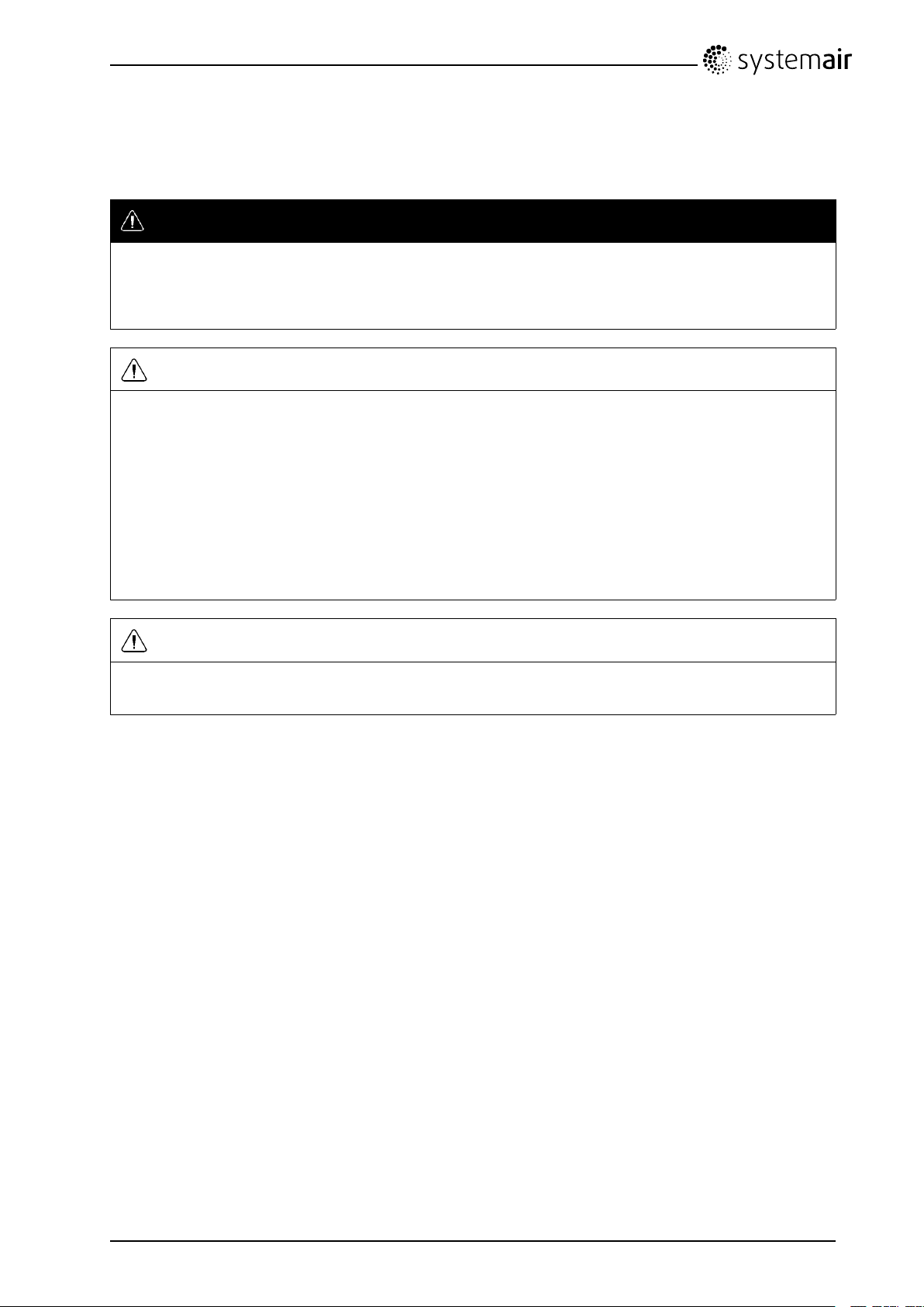
2Warnings
Thefollowingadmonitionswillbepresentedindifferentsectionsofthedocument:
Danger
•Makesurethatthemainssupplytotheunitisdisconnectedbeforeperforminganymaintenanceor
electricalwork!
•Allelectricalconnectionsandmaintenanceworkmustbecarriedoutbyanauthorizedinstallerand
inaccordancewithlocalrulesandregulations.
Warning
•Thesystemshouldoperatecontinuously,andonlybestoppedformaintenance/service.
•Theinstallationoftheunitandcompleteventilationsystemmustbeperformedbyanauthorized
installerandinaccordancewithlocalrulesandregulations.
•Bewareofsharpedgesduringmountingandmaintenance.Useprotectivegloves.
•AlthoughtheMainssupplytotheunithasbeendisconnectedthereisstillriskforinjuryduetorotating
partsthathavenotcometoacompletestandstill.
•Makesurethatltersaremountedbeforestartingtheunit.
•Thisproductmustonlybeoperatedbyapersonwhichhassuitableknowledgeoreducationwithin
thiseldorcarriedoutwiththesupervisionofasuitablyqualiedperson.
Caution
•Donotconnecttumbledryerstotheventilationsystem.
•Ductconnections/ductendsmustbecoveredduringstorageandinstallation.
3Aboutthisdocument
ThisinstallationmanualconcernsairhandlingunittypeSAVEVTR300/BmanufacturedbySystemairAB.
Themanualconsistsofbasicinformationandrecommendationsconcerningthedesign,installation,
start-upandoperation,toensureaproperfail-freeoperationoftheunit.
Thekeytoproperandsafeoperatingoftheunitistoreadthismanualthoroughly ,usetheunitaccordingto
givenguidelinesandadheretoallsafetyrequirements.
4Productinformation
4.1General
TheSAVEVTR300/Bisaheatrecoveryventilationunit,withabuiltinrotatingheatexchanger.TheSA VE
VTR300/Bissuitableforhouseswithupto240m
TheSAVEVTR300/Bsupplieslteredoutdoorairtoresidentialareasandextractairfrombathroom,
kitchenandwetrooms.SAVEVTR300/Bisequippedwitha1670Welectricalre-heaterbattery.
SAVEVTR300/BInstallationandService
208348
2
heatedlivingarea.
2
SystemairAB
Page 5

4.2LeftandRightmodels
Therearetwomodeloptions,right(R)andleft(L)model.Thedifferentmodelsarerecognizedbythe
placingoftheinternalcomponentsandthesupplyairoutlet,whichissituatedonleftsideoftheunitonan
(L)unitandontherighthandsideonan(R)unit.
Note:
Thisdocumentdescribesaleft(L)model.Theinsideofaright(R)modelismirrored.
4.3Transportandstorage
TheSAVEVTR300/Bshouldbestoredandtransportedinsuchawaythatitisprotectedagainstphysical
damagethatcanharmpanelsetc.Itshouldbecoveredsodust,rainandsnowcannotenteranddamage
theunitanditscomponents.
Theapplianceisdeliveredinonepiececontainingallnecessarycomponents,wrappedinplasticona
palletforeasytransportation.
SAVEVTR300/BInstallationandService
208348
3
SystemairAB
Page 6

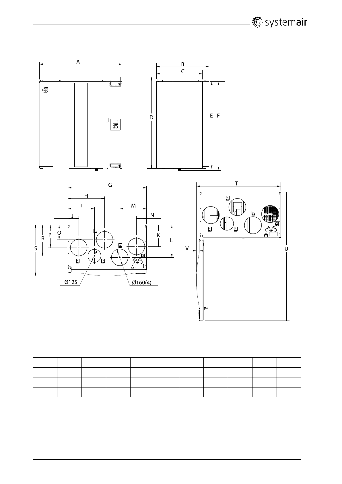
4.4Technicaldata
A
B
C
D E F
G
T
V
U
H
I
J
K
L
M
N
O
P
R
S
Ø160(4)
Ø125
4.4.1DimensionsandWeight,Lmodel
Fig.1Dimensionsandweight,Lmodel
Measuresinmmandweightinkg.
AB
762485
LMN
20625510413621630349078812062766
1.Includinghatch
2.Includingbracket
C
1
423
DEF
2
84280482475840525897121
O
PR
G
S
HIJK
TUVWeight
SAVEVTR300/BInstallationandService
208348
4
SystemairAB
Page 7
4.4.2DimensionsandWeight,Rmodel
Ø160(4)
Ø125
V
T
A
B
G
H
I M
J
N
C
D
E F
R
U
P
O
K
L
S
Fig.2Dimensionsandweight,Rmodel
Measuresinmmandweightinkg.
AB
762486
LMN
C
1
423
DEF
2
842804824758354255104206
O
PR
G
S
HIJK
TUVWeight
1.Includinghatch
2.Includingbracket
SAVEVTR300/BInstallationandService
208348
5
SystemairAB
3112589714121629649078912062866
Page 8
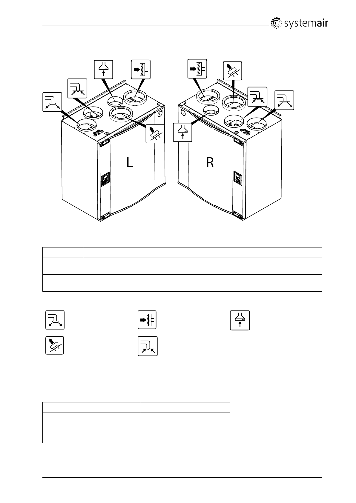
4.4.3Ductconnections
L R
Fig.3Ductconnections
PositionDescription
R
L
Symbol
Righthandmodel(Supplyairconnectionissituatedontherighthandsideoftheunit
viewedfromthefront)
Lefthandmodel(Supplyairconnectionpanelissituatedonthelefthandsideofthe
unitviewedfromthefront)
Description
SupplyairOutdoorairCookerhoodair
ExhaustairExtractair
Symbol
Description
4.4.4Powerconsumptionandfusesize
Re-heater1670W
Symbol
Description
Fans176W
Totalpowerconsumption1846W
Fuse10A
SAVEVTR300/BInstallationandService
208348
6
SystemairAB
Page 9

5Installation
Thissectiondescribeshowtoinstalltheunitcorrectly.Toensureaproperandfail-freeoperation,itis
importantthattheunitisinstalledaccordingtotheseinstructions.
5.1Unpacking
Verifythatallorderedequipmentaredeliveredbeforestartingtheinstallation.Anydiscrepanciesfromthe
orderedequipmentmustbereportedtothesupplierofSystemairproducts.
5.2Where/howtoinstall
TheSAVEVTR300/Bshouldpreferablybeinstalledinaseparateroom(e.g.storeroom,laundryroom
orsimilar .).
Whenchoosingtheinstallationposition,considerationmustbetakenthattheunitrequiresregular
maintenance.Leavefreespaceforopeningofthefronthatchinordertoperformserviceandmaintenance
oncomponentsinsidetheunit.
TheSAVEVTR300/Bissuppliedwithapproximately1mcableandplugfor230V,singlephaseearthed
connectionplacedatthebottomoftheunit.
Recommendedinstallationlocationfortheoutdoorairintakeisthenorthernoreasternsideofthebuilding
andwithadistancetoopeningsfordischargeofstaleventilationair,kitchenventilator,centralvacuum
system,wastewaterdrainageandotherpollutionsourceslikeexhaustfromtrafcetc.Staledischarge
airshouldideallybeledviaaroofunittotheoutsideandwithagooddistancetoanyoutdoorairintake,
windowsetc.
5.3Installationprocedure
Note:
Itisrecommendedtoremovetheheatexchangerbeforetheinstallationtomaketheunitlighter.Theheat
exchangerweighsabout14kg.Howtoremovetheheatexchanger,seechapter5.3.1steps1through3.
1.Preparethesurfacewheretheunitistobemounted.Makesurethatthesurfaceisat,vertical
andthatitsupportstheweightoftheunit.Performtheinstallationinaccordancewithlocalrules
andregulations.
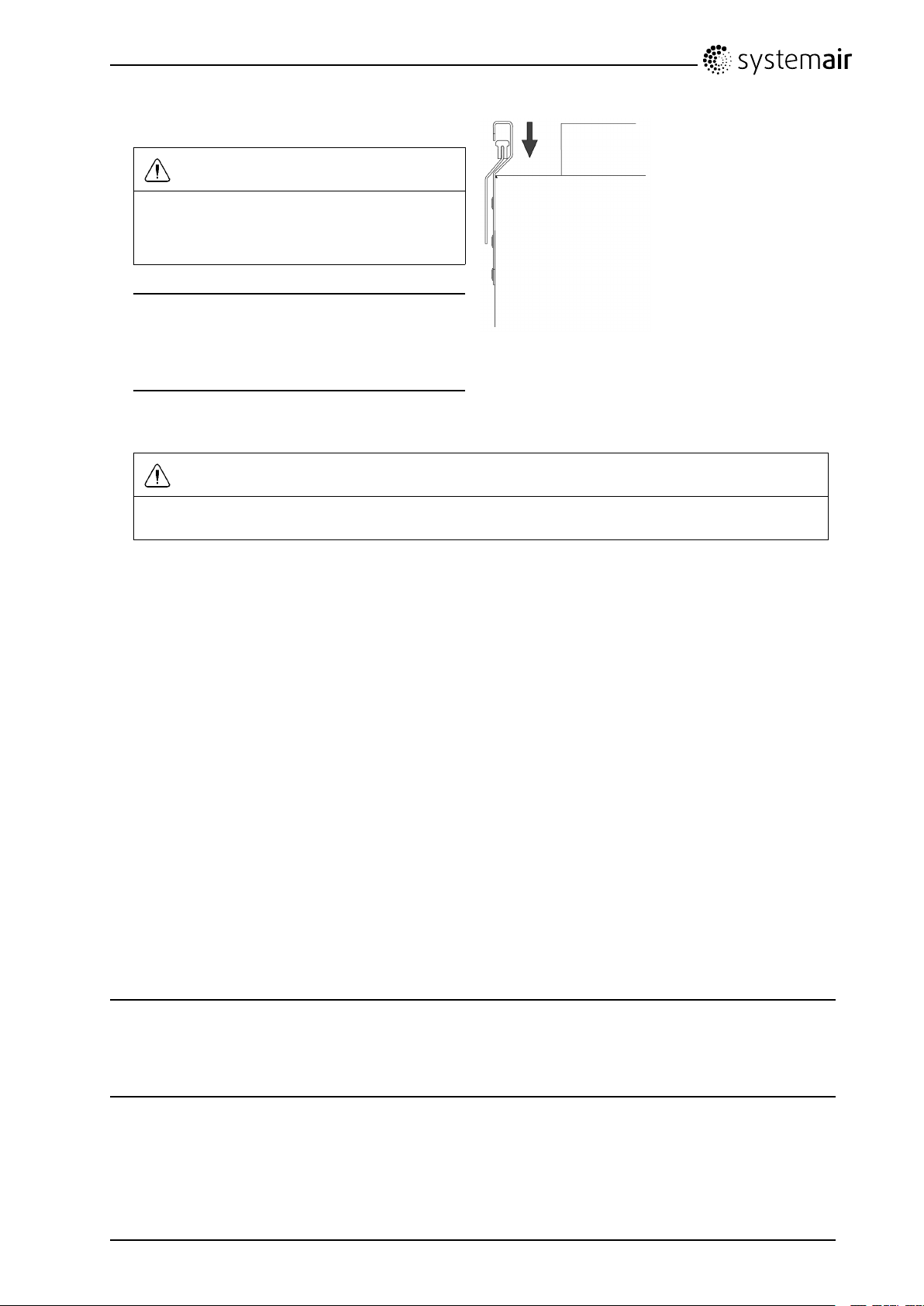
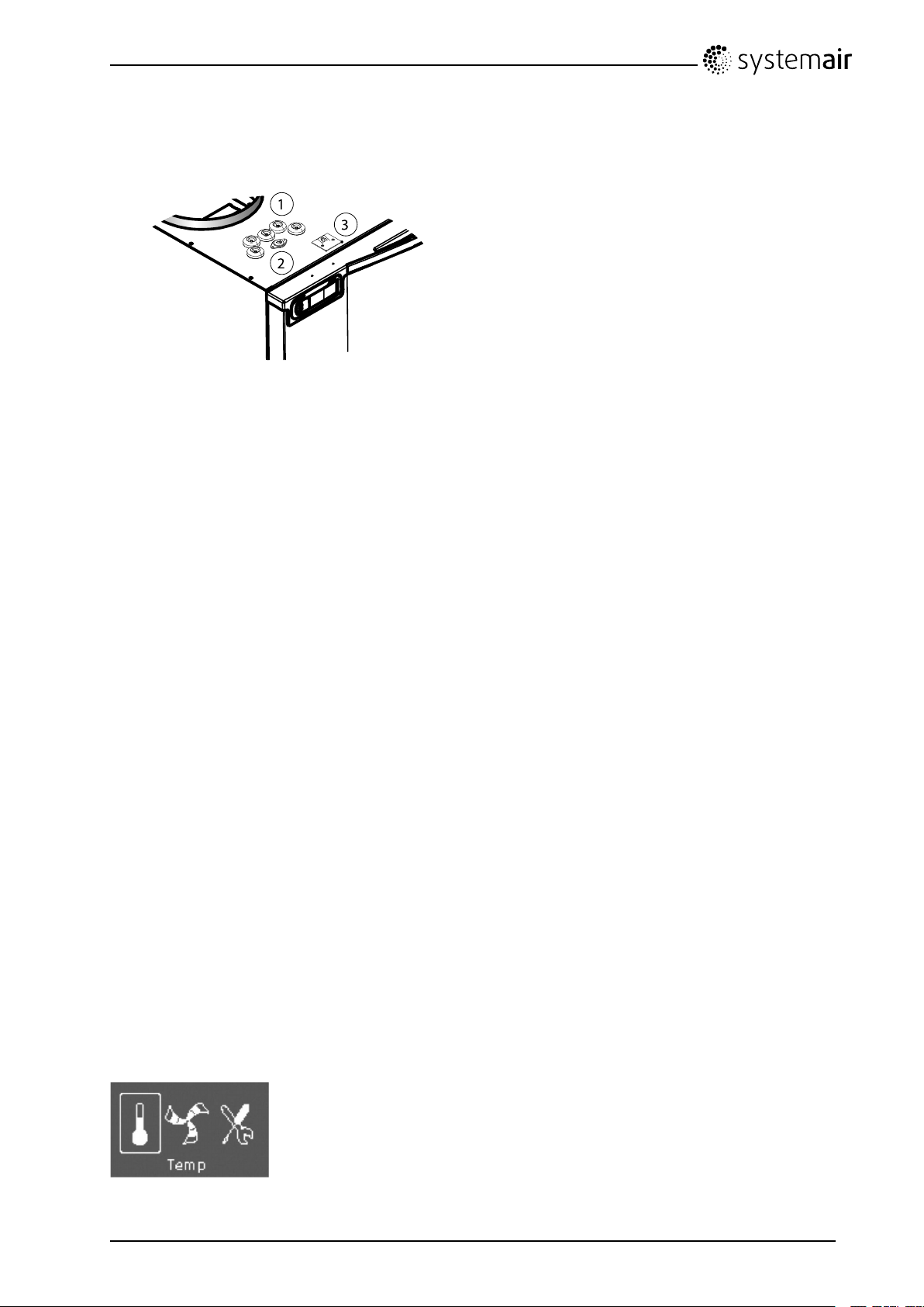
2.Fitthemountingbracket(1)withtheanti-vibration
pad(2)tothewallwithenclosedscrews.Use
appropriateholestoscrewthebracketrmlyto
thewall.Bottomsideofbracketshouldbe40
mm(H)belowtopofunitposition.
Note:
Makesurethatthemountingbracketis
completelyhorizontaloncemountedonthewall.
Checkwithaspiritlevel.
SAVEVTR300/BInstallationandService
208348
7
SystemairAB
Page 10
3.Lifttheunitinplace
Warning
Bewareofsharpedgesduringmountingand
maintenance.Useprotectivegloves.
Considertheunitweightwhenmounting!
Note:
Makesurethattheunitiscompletelyvertical
andhorizontaloncemountedonthewall.Check
withaspiritlevel.
4.Connecttheunittotheductsystem.Makesurethatallnecessaryaccessoriesareusedtocreatea
functionalventilationsolution.
Warning
Theinstallationoftheunitandcompleteventilationsystemmustbeperformedbyanauthorized
installerandinaccordancewithlocalrulesandregulations.
5.Remounttheheatexchangerifitwasremovedbeforetheinstallation.Seechapter5.3.1steps4and5.
5.3.1Howtoremoveandremounttheheatexchanger
1.Openthefronthatch.
2.Disconnecttheheatexchangerpowersupplyandtherotorsensor.Bothcablesarefoundbesidethe
heatexchanger.
3.Pullouttheheatexchanger.Someforcemaybeneeded.
4.Remounttheheatexchanger .Don’tforgettoreconnecttheheatexchangerpowerandsensorcables.
5.Closeandlockthefronthatch.
5.4Condensationdrainage
Ingeneralnocondensationdrainageisneededforrotationalheatexchangersatdryconditions.However,
ifalotofhumidairispresentintheresidence,acondensationdrainagemightbeneeded.Drainage
connectionisavailableasanaccessoryandcanbeorderedseperate.Installationinstructionsforthe
drainageareenclosedinthedrainagepipesdelivery.
Note:
Thedrainageconnectionispluggedinthebottomoftheunitatdelivery.T ousethedrainage:removethe
rubbersealandandconnectthedrainagepipe.Connectthedrainagepipetothesewer.Thewatercan
notbeledstraighttothesewerwithoutawatertrap.
SAVEVTR300/BInstallationandService
208348
8
SystemairAB
Page 11
6Commissioning
1
2
3
4
Connecttheunitelectricallytothemainswiththeenclosedplug.
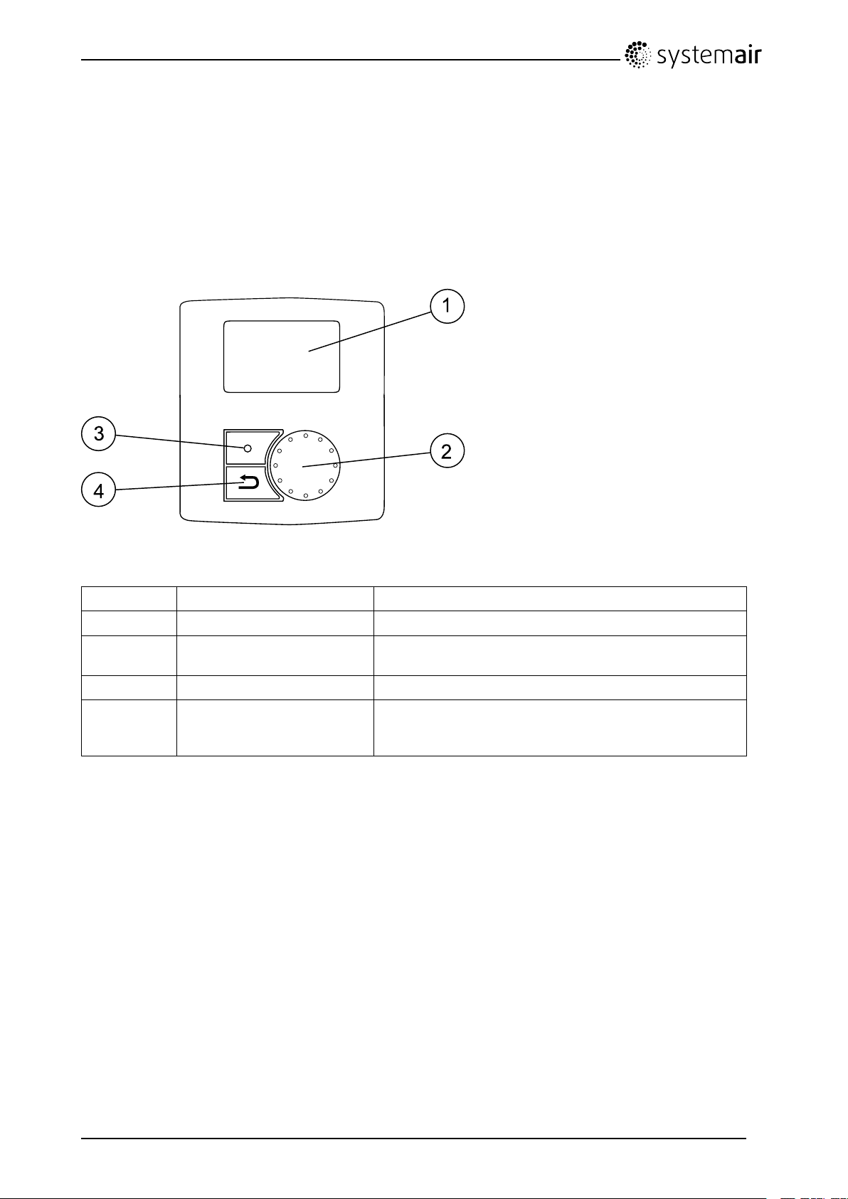
6.1Controlpanel
Thecontrolpanelisusedtomakethenecessaryadjustments.
Fig.4Controlpanel
PositionDescriptionExplanation
1Display
2
3
4
SELECTIONknob
CONFIRMbuttonConrmmenuchoicesorsettingsbypressingthebutton
BACKbuttonStepbackinthemenulevelsandtoabortaninitiated
Showssymbols,menusandsettings
Movethroughthemenulistsorchangesettingsand
valuesbyturningtheknobleftorright
parameterchangeandrestoretheoriginalvalueby
pressingthebutton
SAVEVTR300/BInstallationandService
208348
9
SystemairAB
Page 12

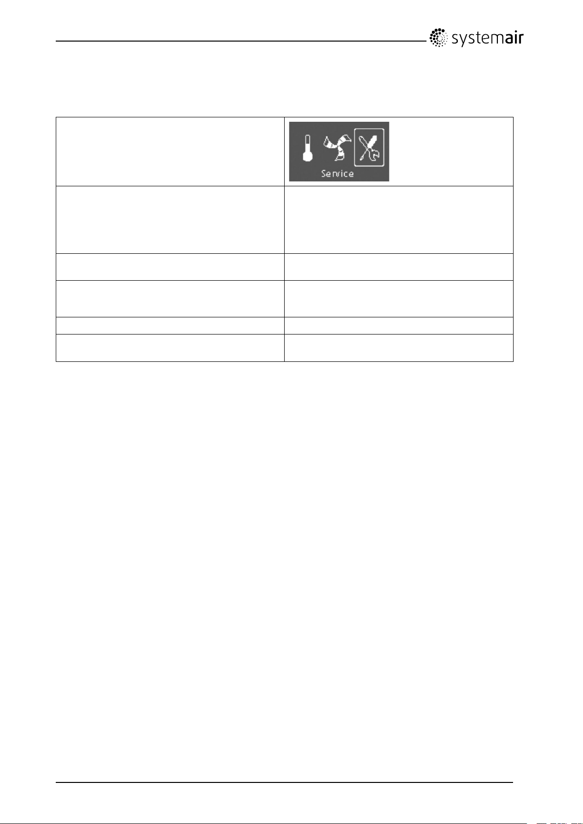
6.1.1Displaysymbols
Symbol
DescriptionExplanation
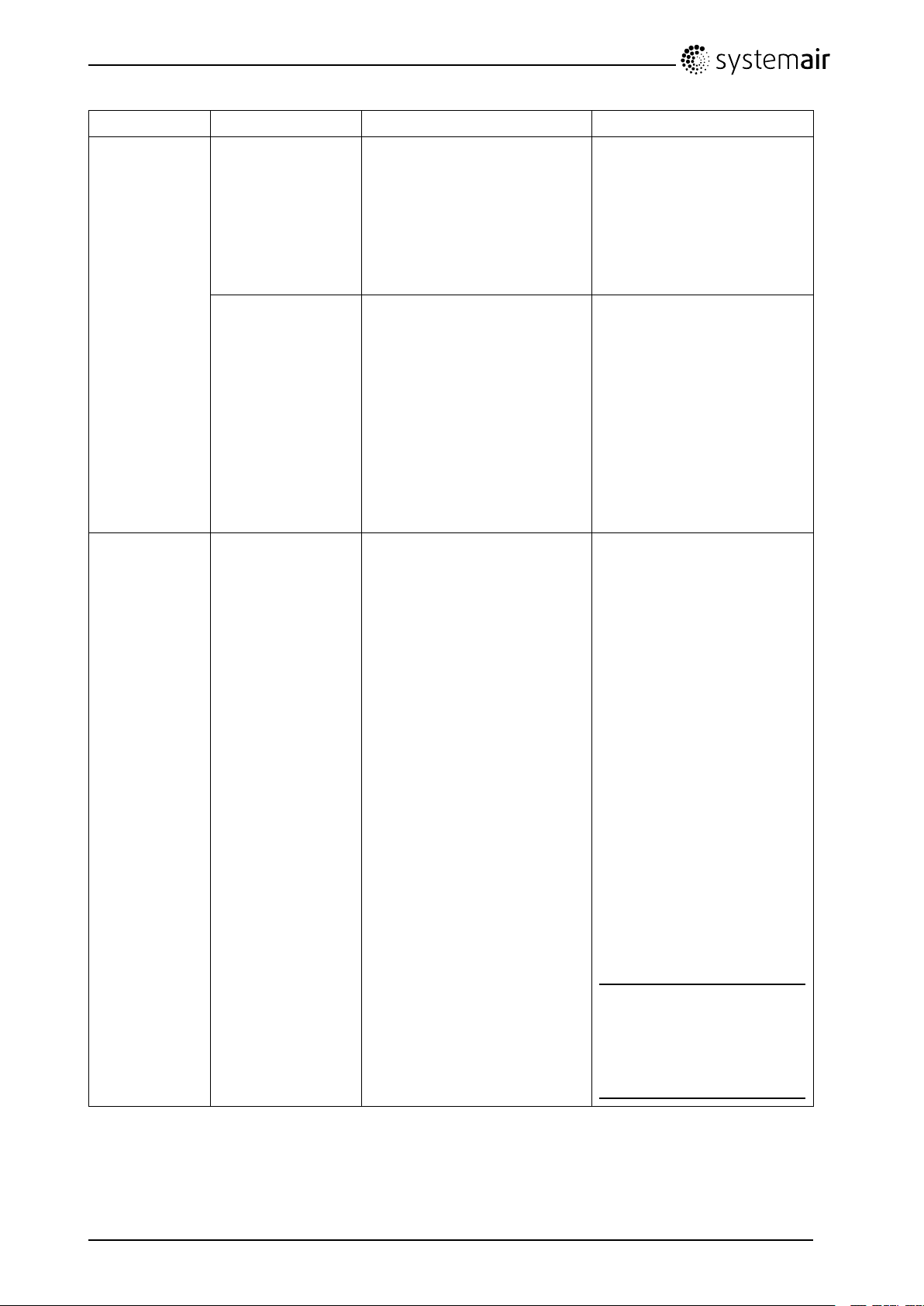
TempIllustratesthecurrentsettemperature.Thetemperature
setpointissetin6steps(fromcompletelyemptytolled
symbol).
TurntheSELECTIONknobtochoosetemperature.
PressCONFIRMtosavethesetting.
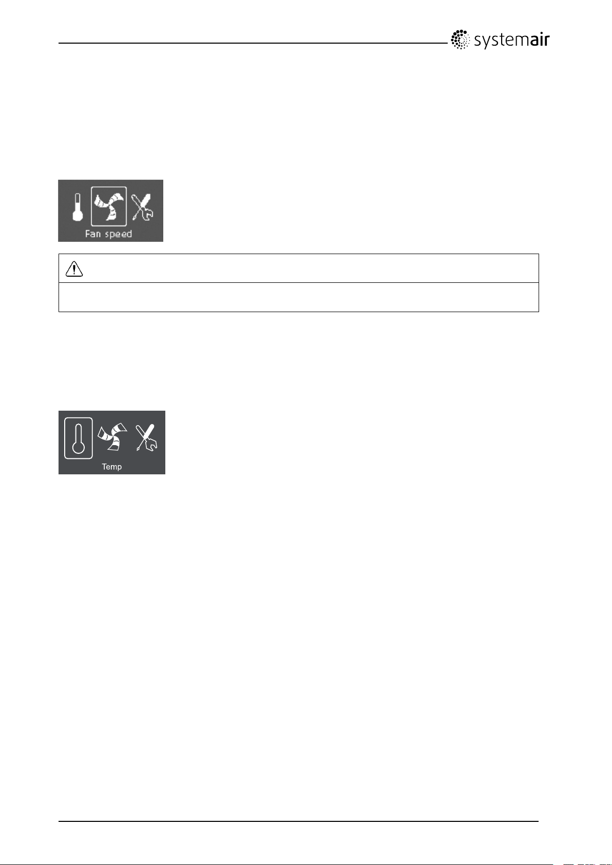
Fanspeed
Illustratesthecurrentfanspeed.Thefanspeedcanbe
setmanuallyin4steps:Off,Low,NomandHigh.
TurntheSELECTIONknobtochoosefanspeed.
PressCONFIRMtosavethesetting.
A.Ventilationoff.
1
B.Lowventilation:Canbeusedwhenleavingthe
buildingforalongerperiod
C.Nominalventilation:Willgiverequiredairchange
undernormalconditions.
D.Maximumventilation:T oincreasetheairowif
necessary.
ServicePressCONFIRMtoaccesstheservicemenu.
Alarm
1.ThefancanbesettoOFFbyactivatingmanualfanstop.Seeservicemenudescriptionunderfunctions.
PressCONFIRMtoaccessthealarmlist.
Note:
Itisnotrecommendedtoactivatemanualfanstop(setfantoOFF)instandardhouseholds.
Ifmanualfanstopisactivated,theunitshouldbeprovidedwithdampersinexhaustandfreshairductsto
avoidcolddraughtandriskofcondensationwhentheunithasbeenstopped.
SAVEVTR300/BInstallationandService
208348
10
SystemairAB
Page 13

6.2Startupwizard
TheStartupWizardisastep-by-stepcongurationtoolthatstartsautomaticallywhentheSAVEVTR
300/Bisstartedforthersttimeorwhen:
•afactoryresetisperformed
•anewprintcardisinstalled(sparepart)
Inthiscasetheunittypemustbeentered(SAVEVTR300/B)
ThefanspeedintheStartupwizardcanbesetbyeitherl/sorapercentagewiththeFancontrol.
•IfAirflowischosen,thesettingswillbeinl/sandsystemcurvesareselected.
•IfSpeedischosen,thesettingswillbeinpercentage.Systemcurvesarenotselectable.
6.2.1Procedure
1.TurntheSELECTIONknobtochooselanguageandpress
CONFIRM
2.Chooseunittype,thischoiceisonlypresentifanewprintcard
isinstalled(sparepart)orwhenafactoryresetisperformed.
3.Setdateandtime
4.Selectheater:None/Electrical/Water
Note:
Thischoiceisavailableonlyafterafactoryreset,seechapter
6.2.2,orwhenanewprintcardisinstalled.
Languages
LanguageENGLISH
Type
SAVEVTR300/B
Time/DateYY/MM/DD
Date:12/09/12
Time:10:00
Weekday:Sat
Heater
Heater:
None/Electrical/Water
SAVEVTR300/BInstallationandService
208348
11
SystemairAB
Page 14

5.Fancontrol.
Fancontrol,Airflow
TurntheSELECTIONknobtoselectthetypeoffancontrolyou
prefer,Airflow(l/s)orSpeed(%)andpressCONFIRM.
Commissionby%,seestep7.
Note:
SystemcurvesarenotselectablewhenSpeedischosen.
Note:
Beforesettingthesystemcurve,seechapter6.3fordetails.
Thisfunctionisimplementedintheunittocompensatetheow
valuesfordifferentsystempressures.
SupplyFan(SF):Totalvaluerange:1–20.ForF7typelter:
1–10,forG3typelter:11–20.
Defaultcurve:2
ExtractFan(EF):Valuerange:1–10
Defaultcurve:2
Note:
Systemcurve
EF:1–10
SF:1–20
ThefactoryinstalledltersareoflterqualityF7forthesupplyair
andG3fortheextractairlter.
Airltersareaccessoriesandcanbeobtainedfromtheinstaller
orwholesaler.
Theltertypeislabelledonthetopofthelter.
6.HereitispossibletochangetheNominal/High/Lowairowon
theExtractandSupplyairfans.Airowinl/s.
Whensettingsaredone,pressCONFIRM.
7.HereitispossibletochangetheNominal/High/Lowfanspeed
ontheExtractandSupplyairfans.Fanspeedin%.System
curvesnotselectable.
Whensettingsaredone,pressCONFIRM.
Airflowl/s
Nom
High100100
Low
Speed%
Nom
High100100
Low
EF
8282
4949
EF
5050
2525
SF
SF
SAVEVTR300/BInstallationandService
208348
12
SystemairAB
Page 15
6.2.2PerformFactoryreset
Howtoperformafactoryresetifnecessary:
1.Entertheservicemenubyselectingtheservice
symbolinthedisplayandpressENTER.
2.Gotopasswordandenterthepassword,
default11 1 1
UsetheSELECTIONknobforeachdigitand
ENTERwiththeENTERbuttonaftereachsetdigit
andchooseNOforthesystemnotbelocked.
3.GotoFunctionsandselectFactoryReset
4.TurntheSELECTIONknobsoYESisshown
andpressENTER.
5.ACCEPTEDisshowninthedisplaywindow
6.TheStartupWizardstartsafterapproximately
10seconds
Password
PasswordXXXX
LockedYES/NO
Functions
Factoryreset
Factoryreset
Reallyreset?YES/NO
ACCEPTED
6.3Systemcurves
Asystemrequiresdifferentpressuresatdifferentairows,whichcanberepresentedbyasystemcurve.
Theintersectionbetweenthesystemlineandthefancurve,istheunit'sworkingpoint.Itisshowingthe
airowthesystemisgoingtohave.Everychangeinthepressureoftheventilationsystem,willgive
risetoanewsystemcurve.
TheK-factorisaconstantthatisthesamethroughoutoneandthesamesystemcurve.IftheK-factorand
thesystempressureisknown,theairowcanbecalculated.Iftherealpressuredropinthesystemis
largerorsmallerthancalculated,theworkingpointandtheairowwillbedifferentthanexpected.
SAVEVTR300/BInstallationandService
208348
13
SystemairAB
Page 16

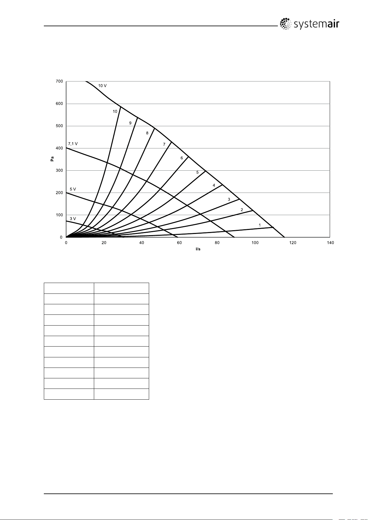
6.3.1Supplyair,F7typelter
0
10 0
20 0
30 0
40 0
50 0
60 0
70 0
0 20 40 60 80 10 0 12 0 14 0
P a
l/s
3 V
5 V
7,1 V
10 V
10
9
8
7
6
5
4
3
2
1
Fig.5Supplyairsystemcurves,F7typelter
SystemcurveK-factor[l/s]
118,03
29,22
37,49
45,82
5
63,70
7
82,28
91,73
101,26
SAVEVTR300/BInstallationandService
208348
4,63
2,93
14
SystemairAB
Page 17

6.3.2Supplyair,G3typelter
10 0
20 0
30 0
40 0
50 0
60 0
70 0
0 20 4 0 6 0 80 10 0 12 0 14 0
P a
l/s
3 V
5 V
7,1 V
20
19
18
17
16
15
14
13
12
11
10 V
Fig.6Supplyairsystemcurves,G3typelter
SystemcurveK-factor[l/s]
1119,03
129,68
137,83
146,02
154,81
163,87
173,05
182,37
191,81
201,32
SAVEVTR300/BInstallationandService
208348
15
SystemairAB
Page 18
6.3.3Extractair,G3typelter
10 0
20 0
30 0
40 0
50 0
60 0
70 0
0 20 40 60 80 1 00 1 20 1 4 0
P a
l/s
3 V
5 V
7,1 V
10 V
10
9
8
7
6
5
4
3
2
1
Fig.7Extractairsystemcurves,G3typelter
SystemcurveK-factor[l/s]
116,47
29,04
37,03
45,40
5
63,41
7
82,12
91,64
101,20
4,29
2,71
SAVEVTR300/BInstallationandService
208348
16
SystemairAB
Page 19

6.4Fanspeedsettings
Thefanspeedcanbesetbyeitherl/s,m
•IfAirflowischosenintheservicemenu,thesettingswillbeinl/sandsystemcurvesareselected.
•IfSpeedischosenintheservicemenu,thesettingswillbeinpercentage.Systemcurvesarenot
selectable.
Thefanspeedmaybeadjustedinfoursteps;off,low,nominalandhigh.Thesesettingscontroltheoutput
signalstothesupply-andextractfans.Thefactorysettingoneachspeedstepsare:
•Off:0l/s
•Low:49l/sor25%.
•Nom:82l/sor50%(atapproximately80Pa).
•High:100l/sor100%.
Theselevelsarepossibletochangeintheservicelevel.Seeservicemenuoverview(chapter8.5)under
functions.
3
/horapercentage.
Note:
Itisnotrecommendedtoactivatemanualfanstop(setfantoOFF)instandardhouseholds.
Ifmanualfanstopisactivated,theunitshouldbeprovidedwithdampersinexhaustandfreshairductsto
avoidcolddraughtandriskofcondensationwhentheunithasbeenstopped.
ThefancanbesettoOFFbyactivatingmanualfanstop.Seeservicemenuoverview(chapter8.5)
underfunctions.
SAVEVTR300/BInstallationandService
208348
17
SystemairAB
Page 20

6.4.1Settingthefanspeed
1.GototheservicemenubyusingtheSELECTIONknob
2.Entertheservicelevelbytypingthepassword,default11 1 1.
UsetheSELECTIONknobforeachdigitandconrmwiththe
CONFIRMbuttonaftereachsetdigitandchoose"NO"forthe
systemnotbelocked.
3.Goto:Functions
Choose:Fancontrol
4.TurntheSELECTIONknobtoselectthetypeoffancontrolyou
prefer,Airflow(l/sorm
3
/h)orSpeed(%)andpressCONFIRM.
Fancontrolbyspeed,seestep7.
5.FancontrolbyAirflowl/s.
Whensettingsaredone,pressCONFIRM.
Choosesystemcurve.
6.PressBACKoncethesystemcurveshasbeensetandgoto
Airflow%.
Whensettingsaredone,pressCONFIRM.
7.FancontrolbySpeed%
Whensettingsaredone,pressCONFIRM.
Password
PasswordXXXX
LockedYES/NO
Functions
—>Fancontrol
Fancontrol
Airflow
Speed
Fancontrol
Airflowsystemcurve
SF:4EF:4
Airflow
EF
l/s
Nom
8282
High100100
Low
Speed%
Nom
4949
EF
5050
High100100
Low
2525
SF
SF
SAVEVTR300/BInstallationandService
208348
18
SystemairAB
Page 21

6.5Defrostlevelsettings
Theunitisequippedwithanautomaticdefrostfunctionthatisactivatedwhenthereisriskoficinginthe
areaaroundtheheatexchanger.Thesetting0-5(table1)determineshowaggressivethedefrostingwill
be.Defaultfactorysettingismode0.
Note:
Theheatexchangershouldwithstandlowoutdoortemperatures,butinthosecaseswhereicingcan
occurpleasebeawareofthatthedefrostsettingwillgenerateanunderpressureinthebuilding.Using
areplace,beawarethatthereisapossibleriskofsmokebeingextractedintothelivingareasdueto
underpressureifdefrostingisactivated.
Table1:Defrostlevels
Defrost
mode
0
1
2
3
4
5
1.Relativehumidityintheextractairatcoldoutdoortemperatures.
2.Innewlyconstructedhousesitmightbenecessarywithahigherdefrostlevelduringtherstwinterperiod.
Relativehumidityindoors
Minimum<20%Dryareas,suchaswarehousebuildingswithfewpeopleor
Low30%-40%Ofcebuildings
Medium40%-60%
High60%-80%
Extremelyhigh>80%
1
Description
Defrostingisturnedoff
industrialbuildingsthatdon’tusewaterintheirproduction
process.
Apartmentsorhouseswithnormalhumidity
Apartmentsorhouseswithhighhumidity
Buildingswithveryhighhumiditylevel.
6.5.1Settingthedefrostlevel
1.Gototheservicemenubyusingthe
SELECTIONknob.
2
2.Entertheservicelevelbytypingthepassword,
default1111.UsetheSELECTIONknobforeach
digitandconrmwiththeCONFIRMbuttonafter
eachsetdigitandchoose"NO"forthesystemnot
belocked.
3.Goto:Functions
Choose:Defrosting
4.Setthemode,0–5
SAVEVTR300/BInstallationandService
208348
Password
PasswordXXXX
LockedYES/NO
Functions
Defrosting
Defrosting
Mode0–5
19
SystemairAB
Page 22

6.6ProgrammingtheWeekschedule
Settheweekscheduleaccordingtobelowprocedure:
1.Gototheservicemenubyusingthe
SELECTIONknob.
2.Entertheservicelevelbytypingthepassword,
default1111.UsetheSELECTIONknobforeach
digitandconrmwiththeCONFIRMbuttonafter
eachsetdigitandchoose"NO"forthesystemnot
belocked.
3.Goto:Weekprogram
4.ChooseWeekprogramagain.
5.Setweekdayandtimeyouwanttheunitto
beinONlevel.Twoperiodsperdaycanbe
programmed.Therestofthetimetheunitwillbein
OFFlevel.
6.Gobacktothepreviousdialogueframewiththe
BACKbuttonandgodowntoFanspeed.
7.Setwhichfanspeedthefanissupposedtobe
runningintheONlevel,choosebetweenLow,
NomorHigh.
Setwhichfanspeedthefanissupposedtobe
runningintheOFFlevel,choosebetweenOFF ,
Low,NomorHigh.
Password
PasswordXXXX
LockedYES/NO
Service
Weekprogram
Weekprogram
Fanspeed
Weekprogram
Day:MON
Per1:07:0016:00
Per2:00:0000:00
Weekprogram
Fanspeed
Fanspeed
Onlevel:low/nom/high
Offlevel:off/low/nom/high
Note:
Ifanelectricalre-heaterbatteryisinstalledand
activeandtheunitisshutdownfromthecontrol
panel,forexamplebychoosingOFF.Whenthe
unitisinOFFlevelintheweekprogram,thefans
willcontinuetorunfor3minutes,topreventthe
heaterfromtriggeringtheoverheatprotection
sensor,beforetheystop.
8.StepbackwiththeBACKbuttonuntilyoureach
themainmenudisplay
SAVEVTR300/BInstallationandService
208348
20
SystemairAB
Page 23

6.7Ext/Forcerun
Itispossibletoprogramextendedtimeyouwanttheunittoworkunderoperationconditionsotherthan
determinedbytheweekschedule.
1.Gototheservicemenubyusingthe
SELECTIONknob.
2.Entertheservicelevelbytypingthepassword,
default1111.UsetheSELECTIONknobforeach
digitandconrmwiththeCONFIRMbuttonafter
eachsetdigitandchoose"NO"forthesystemnot
belocked.
3.Goto:Ext/ForceRun
4.Setthetimeinminutestheunitistorunin
extended/forcedrunningmode.Valuerange:
0–240minutes.
Setthefanspeedforthismode.Choosebetween
Low,NomorHigh.
Defaultvalue:Nom.
Password
PasswordXXXX
LockedYES/NO
Service
Ext/ForceRun
Ext/ForceRun
Minutes:0
Fanspeed:Nominal
6.8Extrafunctions
Theunitisequippedwithanumberofextraon/offfunctionswhichcanbeactivatedfromexternalon/off
switchesthatcanbeconnectedtothedigitalinputsonthemainprintcard(seewiringdiagram).
Thefollowingpossibilitiesareavailable:
•Digitalinputs1–3:Byconnectingon/offswitchestotheseinputsit’spossibletochoose3individual
fanspeedsettingsinthecontrolpaneldependingonatemporaryneedforthebuilding(forexample
loweringtheextractairfanspeedwhenanopenreplaceisused).Seechapter8.5.
DI3,ispreparedandalreadyconnectedinternallyforeasyaccessontheunit.Seechapter6.10.
•Digitalinput4:Makesitpossibletodisabletheintegratedelectricalre-heater
Activatedinputmeansthattheelectricalre-heaterisdisabled.
•Digitalinput5:ActivatetheExtended/forcedrunningfunctionwitharetractiveswitch.Thefunction
overridescurrentfanspeedsettingsandrunsinforcedmodeaccordingtothesettingsinService->
Ext/Forcerun.ChoosebetweenLow,NomandHighforthisfunction.
Theinputiscalculatedbasedonthesignalsfromanimpulse-switch.Ifastandardswitchisused,the
countdownofthesettimestartswhentheswitchisswitchedoff.
•Digitalinput7:Home/leave,switchingonthisinputdecreasestheset-pointforsupplyair-tempwith
10°C.Thisfunctionisusedwhenthebuildingisuninhabitedforalongerperiod.Thisfunctionis
howevernotworkingiftheunithasbeenconguredtooperatewithahotwaterheater.
ItisrecommendedtoconnecteitherofDI1,DI2orDI3inparallelwithDI7.IfDI7isactivated,setthe
fansspeedtomin.FanspeedsettingsaredonewhenconguringDI1,DI2orDI3.
Seemenuoptionsin“ServicemenuOverview”(chapter8.5).
SAVEVTR300/BInstallationandService
208348
21
SystemairAB
Page 24

6.9Electricalconnections
1
4
10
8 3
5
7
6
9
1
2
11
TheSAVEVTR300/Biswiredinternallyfromfactory.
Theelectricalconnectionboxcanbefoundonthesupplyairoutletsideoftheunitbehindacoverplate.
Theprintcard(1)caneasilybetakenoutfromtheunit.
Fig.8Printcardposition
6.9.1Printcardlayout
TheSAVEVTR300/Bisequippedwithbuilt-inregulationandinternalwiring.
Thegureshowstheprintcard.Seewiringdiagramformoreinformation.
Fig.9Printcard
PositionDescription
1Mainprintcard
2
3
SAVEVTR300/BInstallationandService
208348
Printcardforelectricalre-heater
Connectiontoexternalcontrolpanel(connectedtounitcasing)
22
SystemairAB
Page 25

PositionDescription
4Mainssupplyconnectionbetweenmainprintcardandelectricalre-heaterprintcard
5
6
7
8
9
10
11
TerminalsforAI1–5(tempsensors)andmotorcontrol
Terminalsforexternalconnections
Terminalsformainssupplyconnections
Terminalsfordigitalinputs(DI1–7)
Terminalsforinternalcontrolpanel.
Terminalsforregulatedpowersupplytoelectricalre-heater
Modbusconnection.See"UsermanualModbus"fordetails.
6.9.2Externalconnectionsontheprintcard
Connectionterminalsforexternalequipmentcanbefoundonthemainprintcardinsidetheelectrical
connectionbox.
Fig.10Externalconnectionsontheprintcard
PositionDescriptionRemark
1
2
3
4
5
6
7
8
9
10
11
12
Outdoor/exhaustairdamper
Outdoor/exhaustairdamperReference
Outdoor/exhaustairdamper
Sumalarm
SumalarmReference
Sumalarm
GNDReference
Watercoolercontrolsignal(AO1)0–10VDC
GNDReference
Waterheatercontrolsignal(AO2)0–10VDC
GNDReference
Damper(AO3)
6.10Externalconnectionsontheunit
Normallyopen,230V1~,max1A
Normallyclosed,230V1~,max1A
Normallyopen,24V ,max1A
Normallyclosed,24V ,max1A
Notused
Twooftheconnectionsonthemainprintcardarewiredtoplugsontheunitcasing:
•connectiontoanexternalcontrolpanelthroughamodularconnector.
Maximumcablelength:50m.
Cabletype:Flat4–conductorCECPhonecable,orequivalent.
SAVEVTR300/BInstallationandService
208348
23
SystemairAB
Page 26
•connectiontoDI3withpossibilitytocongurethefanspeedsindividuallythroughapotentialfree
0
2
1
3
on/offswitch
Defaultsettings:SF=High,EF=Low.
1.Cableglands
2.ConnectiontoDI3throughapotentialfreeon/offswitch
3.Connectiontocontrolpanel
7Beforestartingthesystem
Whentheinstallationisnished,checkthat:
•Theunitisinstalledinaccordancewiththeinstructions
•Theunitiscorrectlywired
•Outdoorandexhaustairdampersandsilencersareinstalledandthattheductsystemiscorrectly
connectedtotheunit
•Allductsaresufcientlyinsulatedandinstalledaccordingtolocalrulesandregulations
•Outdoorairintakeispositionedwithsufcientdistancetopollutionsources(kitchenventilatorexhaust,
centralvacuumsystemexhaustorsimilar)
•Allexternalequipmentisconnected
•Theunitiscorrectlyconguredandcommissioned
•Theweekscheduleandfanspeedsettingsarecorrectlyprogrammed.
8Operation
8.1Settingtemperature
Thesupplyairtemperatureissetmanuallyin6stepsinthemainmenudisplaybychoosingthe
temperaturesymbol.
Ifanelectricalorwaterre-heaterisinstalledthetemperaturesetpointsare:
12.0,14.5,17.0,19.5and22.0°C.Defaultvalue:12.0°C.
Ifthere-heaterisdeactivated,thetemperaturestepsare:
15.0,16.0,17.0,18.0or19.0°C.Defaultvalue:15.0°C.
Eachtemperaturestepisillustratedbyincreasingthellingofthetemperaturesymbol.
Anunlledtemperaturesymbolisthe6thsetpointandwillactivatemanualsummermode.Seechapter8.3
SAVEVTR300/BInstallationandService
208348
24
SystemairAB
Page 27
8.2Manualsettingoffanspeed
Te mp
Itispossible,atanytime,tomanuallysetthefanspeedinthemainmenudisplay .Bychoosingthefan
symbolandconrmingitispossibletoincreaseordecreasethefanspeedinthe4steps:Off,Low,
NomandHigh.
Bydoingso,youoverridetheprogrammedweekschedulefortheunituntiltheendofthepresenttime
periodintheweekprogram(chapter6.6).
Warning
ThefancanbesettoOFFbyactivatingmanualfanstop.Seeservicemenuoverview(chapter8.5)
underfunctions.
8.3Manualandautomaticsummermode
Manualsummermodeoccursifnotemperaturestepisselected.Thetemperaturesymbolonthemain
menuisthencompletelyempty .
Iftheelectricalre-heaterisactivated,itwillswitchoffduringmanualsummermode.Manualsummer
modegoesautomaticallytostep1(setpoint12°C)aftertwominutesifthesupplyairtemperatureis
+5°Corbelow.
Ifawaterheaterbatteryisinstalledandactivated,themanualsummermodegoesautomaticallytostep1
(setpoint12°C)iftheoutdoorairorsupplyairtemperatureis+5°Corbelow.
Theunitwillautomaticallyalternatebetweenwinteroperationwithheatrecoveryandsummeroperation
withoutheatrecovery .
8.4Coolrecovery
Iftheoutdoorairiswarmerthantheextractairandthesupplyairisabovethesetpoint,coolrecovery
occurs.Thisconditionblockstheheatregulationprocess.
SAVEVTR300/BInstallationandService
208348
25
SystemairAB
Page 28

8.5Servicemenuoverview
Entertheservicemenubyselectingtheservicesymbolinthedisplay.
MenuLevel1MenuLevel2MenuLevel3Explanation
Service
Password
Service
Change
Password
Service
Filter
period
Service
Time/Date
Password
PasswordXXXX
LockedYES/NO
Change
password
ActualXXXX
NewXXXX
ConfirmXXXX
Filterperiod
Timeto
replace:
12month
ResetNO/YES
Time/Date
YY/MM/DD
Entertheservicelevel
bytyping1111.Usethe
SELECTIONknobforeach
digitandconrmwiththe
CONFIRMbuttonaftereach
setdigit.NOwillunlockthe
systemandallowparameter
changes.
Setnewpasswordif
necessary.
Incasethenewpassword
wouldbeforgottenor
misplacedit’sstillpossible
toentertheservicelevelby
writing8642.Thisoverrides
theearliersetpassword.
Showsselectedtimeinterval
betweenlterchange.
SetResetofthelterperiod
toYESaftercompletedlter
change.
Settimebetweenlter
changes.
Showscurrentsetdateand
time.
Date:
12/09/12
Time:10:00
Weekday:Sat
Service
Ext/Force
Run
Ext/ForceRun
Minutes:0
Fanspeed:
Nominal
SetCorrectdateandtime.
Usethisdialogueframeto
programextendedtimeyou
wanttheunittoworkunder
operationconditionsother
thandeterminedbytheweek
schedule.
Showssettimefor
extended/forcedrunning.
ShowsSetfanspeed.
Setthetimethattheunitisto
runinextended/forcedmode.
Valuerange:0–240minutes.
Setthefanspeedforthis
mode.ChoosebetweenLow,
NomorHigh.
Defaultvalue:Nom.
SAVEVTR300/BInstallationandService
208348
26
SystemairAB
Page 29
MenuLevel1MenuLevel2MenuLevel3Explanation
Service
Weekprogram
Weekprogram
Week
program
Weekprogram
Day:MON
Per1:07:0016:00
Per2:00:0000:00
Weekprogram
Fanspeed
Fanspeed
Onlevel:low/nom/high
Offlevel:
off/low/nom/high
Service
Fanspeedlog
Fanspeed
log
Level:1–5
Reset:NO/YES
SF:140/140
EF:140/140
Programhowyouwantthe
unittooperateaccording
totheweekschedule.It’s
possibletoset2periodsper
day.
Setweekdayandtimeinterval
forthetimeyouwanttheunit
tobeinONmode.
Usethisdialogueframeto
determinetheONandOFF
functionforthefansinthe
weekschedule.
SetONlevel.
ChoosebetweenLow,Nomor
High.
Defaultvalue:Nom
SetOFFlevel.
ChoosebetweenOFF,Low,
NomorHigh.
Defaultvalue:Low.
Usethisdialogueframetosee
howthefanshaveoperated
duringthetime(h)theyhave
beenactive.
Thespeedsareshownin5
differentlevels:
•Level1:0%
•Level2:1–29%
•Level3:30–44%
•Level4:45–59%
•Level5:60–100%
Choosebetweenthelevels
toseethetimeinhoursthe
fanshavebeenactiveinthe
differentlevels.
ResetYesresetstheSFand
EFtimeintheleftcolumnfor
alllevels.Therightcolumn
continuestocountaheadand
cannotbereset.
Note:
Factoryreset(see
Functions–>Factory
reset)willnotaffectthis
function
SAVEVTR300/BInstallationandService
208348
27
SystemairAB
Page 30
MenuLevel1MenuLevel2MenuLevel3Explanation
Service
Functions
Heater/Cooler
Functions
Heater/Cooler
Heater:
None/Electrical/Water
Cooler:None/Water
Functions
Frost
Frostprotection
Alarmlimit:7°C
protection
Functions
Systemcurve
Systemcurve
EF:1–10
SF:1–20
Functions
Fancontrol
Fancontrol
Airflow
Speed
EF
Fancontrol
Airflow
SF
l/s
Airflow
Nom
8282
High100100
Low
Fancontrol
Airflowunit
4949
Usethisdialogueframetoset
uptheunitforheatingand/or
cooling.
SetHeatertoNone,Electrical
orWater.
SetCoolertoNoneorWater.
Showscurrentsetfrost
protectionalarmlimitin°Cfor
theinstalledwatercoil.
SetAlarmlimitin°C.
Defaultvalue:7°C.
Thisfunctionistocompensate
theowvaluesfordifferent
systempressures.
Seechapter6.3
Selectthetypeoffancontrol
youprefer.Fancontrolbyl/s
or%
Usethisdialogueframeto
setthefanspeedinl/s.The
speedcanbesetindividually
foreachfan
EF:Extractfan,
SF:Supplyfan
SetthefanspeedforEFand
SFforeachstep(Low,Nom,
andHigh.
Defaultvalue:l/s
Airflowunit
Fancontrol
Speed
Functions
Manualfan
stop
l/s
m3/h
Speed%
Nom
EF
5050
High100100
Low
2525
Manualfanstop
Allowmanualfanstop
Y/N
SF
Usethisdialogueframeto
setthefanspeedin%.The
speedcanbesetindividually
foreachfan
EF:Extractfan,
SF:Supplyfan
SetthefanspeedforEFand
SFforeachstep(Low,Nom,
andHigh.
Setifitshouldbepossible
toturnoffthefansintheunit
manuallyfromthecontrol
panel.
ChosebetweenYandN.
IfYisselectedthefanscan
beturnedoffbyturningthe
SELECTIONknobtoempty
fan
SAVEVTR300/BInstallationandService
208348
28
SystemairAB
Page 31
MenuLevel1MenuLevel2MenuLevel3Explanation
Functions
Analoginput
Analoginput
1:SS20.0
2:ETS23.0
3:Unused
4:OT/FPS20.0
5:OS10.5
Functions
Analogoutput
Analogoutput
A01auto/man/off0.0V
A02auto/man/off7.3V
A03auto/man/off0.0V
Functions
Digitalinput
Digitalinput
DI1ON/OFF
DI2ON/OFF
DI3ON/OFF
DI4ON/OFF
DI5ON/OFF
DI6ON/OFF
DI7ON/OFF
Showsanalogueinputsfrom
activetemperaturesensors.
SS:Supplyairtempsensor.
ETS:Extractairtempsensor.
OT/FPS:Overheatprotection
sensor/Frostprotection
sensor.
OS:Outdoorairtempsensor.
Showscurrentanalogue
outputsin0–10Vtohot/cold
wateractuator.
SetAO1(Analogueoutputto
hotwateractuator)toauto,
manoroff.
Defaultvalue:auto.
SetAO2(Analogueoutputto
coldwateractuator)toauto,
manoroff.
Defaultvalue:auto.
AO3Notused.
Showscurrentsettingofthe
digitalinputsONorOFF
DI1:Fanconguration
DI2:Fanconguration
DI3:Fanconguration
DI4:Heaterdeactivated
Functions
ConfigDI1–3
ConfigDI1–3
Default:
1SFhighEFhigh
2SFlowEFlow
3SFhighEFlow
DI5:Extended/forcedrunning
DI6:Rotorsensor
DI7:Home/leave
Usethisdialogueframeto
sethowyouwantthefans
toreactto3differentdigital
inputswhentheyareswitched
on(thesettingsinthecolumn
totheleftareexamples).
Potentialfreeswitchesneed
tobeconnectedphysicallyto
terminalsonthemainprint
cardtoobtainthedifferent
functions.Seethewiring
diagramformoreinformation.
Setthesupplyairfan(SF)and
extractairfan(EF)individually
tooff,low,nomorhighfor
digitalinputs1–3
SAVEVTR300/BInstallationandService
208348
29
SystemairAB
Page 32

MenuLevel1MenuLevel2MenuLevel3Explanation
Functions
DI4–7
DI4–7
4Stopheat
5Extrun
6Rotor
7Home/Leave
DI4–7aredefaultsetfrom
factoryandcan’tbechanged
bytheuser.Belowfollows
ashortdescriptionofeach
function.
DI4:Makesitpossible
todisabletheintegrated
electricalre-heater.Activated
inputmeansthattheelectrical
re-heaterisdeactivated.
DI5:Activatethe
Extended/forcedrunning
function.Thefunction
overridescurrentsetfan
speedsettingsandruns
accordingtothesettingsin
Service->Ext/Force
run.ChoosebetweenLow,
NomandHighforthisfunction.
Theinputiscalculatedbased
onthesignalsfroman
impulse-switch.Ifastandard
switchisused,thecountdown
ofthesettimestartswhenthe
switchisswitchedoff.
DI6:Rotorsensor.
DI7:Switchingonthisinput
decreasesthesupplyairtemp
setpointwith10°C.
Thisfunctionisusedwhenthe
buildingisuninhabitedfora
longerperiod.
Itisrecommendedtoconnect
DI7andDI1orDI3inparallel.
IfDI7isactivated,setthe
fansspeedtomin.Fan
speedsettingsaredonewhen
conguringDI1/DI3.
Note:
The“Home/Leave”functionis
notworkingifWaterheateris
activated.
SAVEVTR300/BInstallationandService
208348
30
SystemairAB
Page 33

MenuLevel1MenuLevel2MenuLevel3Explanation
Functions
Digitaloutput
Digitaloutput
1:SF67%
2:EF67%
3:RotON/OFF
4:ALARMY/N
5:DmpY/N
6:ReheaterY/N
Functions
Defrosting
Functions
Modbus
Defrosting
Mode0–5
Modbus
Address1
Baud9600/19200
ParityNone/Even/Odd
ShowsThecurrentsettings
ofdigitaloutputs1–6(the
settingsinthecolumntothe
leftareexamples).
1:SF67%:Currentsetspeed
ofthesupplyairfan(shownas
percentageofthemaximum
speed).
2:EF67%Currentsetspeed
oftheextractairfan(shownas
percentageofthemaximum
speed).
3:Showsiftherotorisactive
ornot.
4:AlarmY/N:Indicatesifthe
sum.alarmisactiveornot
5:DmpOFF:Outdoor/exhaust
airdamperisonoroff.
6:ReheaterY/N:Indicates
iftheelectricalre-heateris
activeornot.
Usethisdialogueframetoset
howaggressiveyouwantthe
defrostingfunctiontooperate
(seechapter6.5).
InformationaboutModbus
communicationandvariables
canbefoundintheModbus
usermanualforresidential
unitsintheonlinecatalogueat
www.systemair.com.
Functions
Factoryreset
Usethisdialogueframeto
returntofactorysettings.
Factoryreset
Reallyreset?YES/NO
SetYESorNO
Note:
Thiswilleraseallyour
personalsettingsthathave
beendonefortheunit.
Service
Language
Languages
Usethisdialogueframeto
returntoselectyourlocal
Language
language.
ENGLISH
SetLanguagebyturningthe
SELECTIONknob.
SAVEVTR300/BInstallationandService
208348
31
SystemairAB
Page 34

MenuLevel1MenuLevel2MenuLevel3Explanation
Service
Versions
VersionSAVE
VTR300/B
Showscurrentsoftware
versions
CDEC
Appl.1.08.00
3.16.00
Boot1.00.01
1.01.00
Service
Alarms
Alarms
FanY
EmT/FrostN
DampY
PbFailN
TempN
FilterY
Note:
Thesoftwareversionsarejust
anexampleandmaydifferin
aspecicunit.
Showsthealarmlistand
whichalarmsthathavebeen
triggered(indicatedbyY).See
alarmlist(chapter9.4.1)
9Service
9.1Warnings
Danger
•Makesurethatthemainssupplytotheunitisdisconnectedbeforeperforminganymaintenanceor
electricalwork!
•Allelectricalconnectionsandmaintenanceworkmustbecarriedoutbyanauthorizedinstallerand
inaccordancewithlocalrulesandregulations.
Warning
•Thesystemshouldoperatecontinuously,andonlybestoppedformaintenance/service
•Althoughthemainssupplytotheunithasbeendisconnectedthereisstillriskforinjuryduetorotating
partsthathavenotcometoacompletestandstill
•Bewareofsharpedgesduringmaintenance.Useprotectivegloves
•Makesurethatltersaremountedintheirplacebeforerunningthesystem
•Thisproductmustonlybeoperatedbyapersonwhichhassuitableknowledgeoreducationwithin
thiseldorcarriedoutwiththesupervisionofasuitablyqualiedperson.
SAVEVTR300/BInstallationandService
208348
32
SystemairAB
Page 35

9.2Internalcomponents
1
14
15
16
13
2
3
4
5
6
7
8
9
10
11
12
Fig.11Internalcomponents
PositionDescription
1Mountingbracket
2Externalconnections
3Extractairsensor
4
5
6
7
8
9Rotormotorandbeltpulley
10Rotatingheatexchanger
11Heatexchangerdrivebelt
12Rotorsensor
13
14
15
16
Overheatprotectionsensor
Internalelectricalre-heater
Extractairlter
Mainprintcard
Supplyairfan
Supplyairlter
Extractairfan
Outdoorairsensor
Supplyairsensor
SAVEVTR300/BInstallationandService
208348
33
SystemairAB
Page 36

9.3Componentdescriptions
9.3.1Fans
ThefanshaveexternalrotormotorsofECtypewhichcanbesteplesslycontrolledindividually20–100%.
Themotorbearingsarelifetimelubricatedandmaintenancefree.Itispossibletoremovethefansfor
cleaning,see“UserManual”formoreinformation.
9.3.2Filters
ThefactoryinstalledltersareoflterqualityF7forthesupplyairandG3fortheextractairlter.Thelters
needtobereplacedwhenpolluted.Newsetsoflterscanbeacquiredfromyourinstallerorwholesaler.
FilterqualityG3canbeinstalledforsupplyairltering.
Theltertypeislabelledonthetopofthelter
Note:
IftypeG3ltersareusedinsteadofF7,thesystemcurveforSupplyFan(SF)mustbechanged:
ForG3typelter:11–20,forF7typelter:1–10.Seechapter6.3.
9.3.3Heatexchanger
SAVEVTR300/Bisequippedwitharotatingheatexchanger.Requiredsupplyairtemperatureistherefore
normallymaintainedwithoutaddingadditionalheat.
Theheatexchangerisremovableforcleaningandmaintenance,see“UserManual”formoreinformation.
9.3.4Printcard
Themainprintcardcontrolsthefunctionsandsettemperaturesoftheunit.
Itispossibletoconnectexternalaccessoriestoterminalsontheprintcardandalsocommunicationto
BMS(BuildingManagementSystem)ModbuscommunicationviaRS-485.Seewiringdiagramformore
information.
9.3.5Temperaturesensors
Fourtemperaturesensors(NTC,10kΩat25°C)areincludedintheunitfromfactoryandpositionedinthe
correspondingairchambers.
Thesensorsareconnectedtothemainprintcard.Seewiringdiagramformoreinformation.
9.3.6ElectricalRe-heaterbattery
There-heaterbatteryispositionedinthesupplyairchamber.
There-heaterisactivatedbyarelayandswitchesonifthesupplyairtemperatureis2Klowerthantheset
pointandswitchesoffifoneormoreofthefollowingconditionsaremet:
1.Ifthesupplyairtemperatureismorethan2Kabovethesetpoint.
2.Iftheoverheatprotectionisactivatedorthesensorismalfunctioning.
3.Iftheemergencythermostatistriggeredorbroken.
4.Ifthesupplyairsensorisinerrorstate.
5.Ifthesupplyairfanisnotrunning.
6.Iftheheaterissettodisabledinthemenu.
SAVEVTR300/BInstallationandService
208348
34
SystemairAB
Page 37

9.3.7Overheatprotectionresetbutton
1
Ifthesupplyairtemperatureislow,itcanindicatethattheoverheatprotectionistriggered.Theoverheat
protectioncanberesetbypressingtheresetbutton(1).
Fig.12Overheatprotectionresetbutton
9.3.8WaterRe-heaterbattery
Awaterre-heaterbattery(optional),whichcanbeacquiredasanaccessory ,canbecontrolledbythe
analogoutputWH(0-10VDC).ThewaterheaterusesAI4forfrostprotection(OT,“Overheatprotection”,
changestoFPS,Frostprotectioninthemenu).
Thefrostprotectionsensorshouldthenbeastraponsurfacesensorsituatedonthereturnwatertube.
Sensortype:TG-A130
Thesupplyairsensor(SS)atAI1mustbereplacedwithaductsensorwhichcanbeacquiredasan
accessory.Sensortype:TG-K360.Seewiringdiagramformoreinformation.
Onlyelectricalorwaterre-heaterisallowed,i.e.ifawaterre-heaterisselected,theelectricalre-heateris
deactivatedandviceversa.
Note:
Ifawaterre-heaterbatteryisinstalledwestronglyrecommendyoutoalsoinstallanoutdoorairdamper
withaspringreturnactuator.
9.3.9WaterCooler
Awatercooler(optional)canbeacquiredasanaccessoryandbecontrolledbytheunit.Ifawatercooler
isinstalledthesupplyairsensor(SS)atAI1mustbereplacedwithaductsensorwhichcanbeacquired
asanaccessory .Sensortype:TG-K360.Seewiringdiagramformoreinformation.
SAVEVTR300/BInstallationandService
208348
35
SystemairAB
Page 38

9.4Troubleshooting
Awarningtrianglewithtextinthedisplayindicatesanalarm.Turnmenuselectortothewarningtriangle
andpressconrmtwicetoviewthealarm.
Ifproblemsshouldoccur,pleasechecktheitemsbelowbeforecallingyourservicerepresentative.
Malfunction
Fansdonotstart
Reducedairow1.Checkthedisplayforalarms.
Action
1.Checkthedisplayforalarms.
2.Checkfuseformainpowersupplyinthedistributionboxforthebuilding
andallthequickconnectorsareconnectedintheunit(quickconnectors
forsupplyandextractairfans).
3.CheckthattheweekprogramisinONmode.Theweekprogrammightbe
inOFFmodewiththefanspeedsettoOFF(chapter6.6)
4.Checkifoneofthedigitalinputs1–3(DI1–3)isactiveandsettooff.This
wouldforceoneorbothfanstostopdependingonthesetup(chapter8.5).
2.Checksettingoffanspeedinthecontrolpanel(chapter6.1.1).
3.Checkweekprogram(chapter6.6).
4.Checkifoneofthedigitalinputs1–3(DI1–3)isactiveandsettooff.This
wouldforceoneorbothfanstostopdependingonthesetup(chapter8.5).
5.Checklters.Changeofltersrequired?
6.Checkdiffuser/louveropenings.Cleaningofdiffusers/louvresrequired?
7.Checkfansandheatexchangeblock.Cleaningrequired?
8.Checkifthebuildingsairintakeandroofunit(exhaust)havebeenclogged.
9.Checkvisibleductrunsfordamageand/orbuildupofdust/pollution.
Theunitcannotbe
controlled
(controlfunctionsare
stuck)
SAVEVTR300/BInstallationandService
208348
1.Resetcontrolfunctionsbypullingoutthemainpowersupplyplugfor
20-30seconds.
2.Checkthemodularcontactconnectionbetweenthecontrolpaneland
themainprintcard.
36
SystemairAB
Page 39

Lowsupplyair
temperature
Noise/vibrations1.Cleanfanimpellers.
1.Checkthedisplayforalarms.
2.Checksetsupplyairtemperatureinthecontrolpanel.
3.Checktheanalogueinputsintheservicemenutoverifythatthetemp
4.Checkiftheoverheatprotectionthermostatisstillalert.Ifnecessary ,
5.Checkifdigitalinput4(DI4)issettooff.Thiswouldforcetheelectrical
6.Checkiftheextractltermustbechanged.
7.Atverycoldoutdoorconditionsanelectricalpreheatingbatterymightbe
8.Checkthebalancebetweenthesupplyandextractair
2.Checkthatthescrewsholdingthefansaretightened.
3.Checkthattheantivibrationpadsarettedatthebottomoftheunit.
sensorsareok(chapter8.5).GotoFunctions>Analogueinput
andverifythetemperaturereadingsfromthetempsensors.
resetbypressingtheresetbutton.Seechapter9.3.7.
re-heaterbatterytobeswitchedoff(chapter8.5)
necessary.Thiscanbeacquiredasanaccessory.
Atverycoldoutdoorconditionsanelectricalpreheatingbatterymightbe
necessary.Thiscanbeacquiredasanaccessory.
9.4.1Alarmlist
AlarmExplanation
FanIndicateserroroneithersupplyor
extractairfan.
EMT/FrostIndicatestriggeredfrostprotection
(incaseofinstalledwaterheating
battery)ortriggeredoverheat
protection(incaseofinstalled
electricre-heaterbattery).
Dothefollowing
Thealarmisdisplayedinthecontrolpanel.
Checkthatquickconnectorsareconnectedforthe
bothfans.
Contactyourinstallationcompanyorplaceof
purchase.
Atriggeredfrostprotectionalarmresultsinthe
following:
•Bothfansstop.
•Outdoorandexhaustairdampersclosed.
•Watervalveopenscompletely(10Vsignalgoes
outtotheactuator).
Theunitwillrestartoncethewatertemperature
reaches+5°Cabovethesetfrostprotection
temperature.
Atriggeredoverheatprotectiongivesanalarminthe
controlpanel.
Resetbypushingtheresetbutton.Seechapter9.3.7.
Iftheproblemcontinuescontactyourinstallation
companyorplaceofpurchase.
SAVEVTR300/BInstallationandService
208348
37
SystemairAB
Page 40

AlarmExplanation
Dothefollowing
Rotor
PbFailErrorinconnectionwithrelay
Temp
Filter
Indicatesarotormalfunction.
cardfortheelectricalre-heater(if
installedandactivated).
Theoverheatprotectionsensor,
automaticreset(ET2)maybe
triggeredduetohightemperature.
Malfunctioninoneormoreofthe
temperaturesensors.
Timeforlterchange.
Thealarmisdisplayedinthecontrolpanel.
•Iftherotatingheatexchangerhasstopped.Check
therotorbelt.Seechapter9.5
•Iftheheatexchangerisstillrotating,checkthatthe
quickconnectorforthesensorisconnectedand
thatthereisanairgapof5-10mmbetweenthe
sensorandthemagnet.
Adjustthegapifnecessary.
Ifthealarmpersists,therotorsensormaybefaulty.
Contactyourinstallationcompanyorplaceof
purchase.
Thealarmisdisplayedinthecontrolpanel.
Theheaterwillnotbeactivated.
FortriggeredET2,wait10–15min.Iftheerror
remains,contactyourinstallationcompanyorplace
ofpurchase.
Thealarmisdisplayedinthecontrolpanel.
Contactyourinstallationcompanyorplaceof
purchase.
Thealarmisdisplayedinthecontrolpanel.
Changelteraccordingtoinstructionsintheuser
guide.
9.5Replacingrotordrivebelt
Danger
•MakesurethattheMainssupplytotheunitisdisconnectedbeforeperforminganymaintenanceor
electricalwork!
Warning
Riskofpersonalinjury!Theheatexchangerweighsabout14kg.Thereisariskthattheheatexchanger
fallsoutoftheunit.
Makesurethatsmallchildrenarenotbeneaththeunitwhentheheatexchangerisremoved!
IfthealarmRotorisraised,seechapter9.4.1,therotordrivebeltmaybedamagedorbroken.
SAVEVTR300/BInstallationandService
208348
38
SystemairAB
Page 41

1
Fig.13Rotordrivebelt
Thereplacementdrivebelt(1)isadjustableanddeliveredwithanippleattachedinoneend.
1.Stoptheunitbydisconnectingthemains.
2.Openthefronthatch.
3.Removethebrokendrivebelt.
4.Usetapetoattachthedrivebelttotherotatingheatexchanger,androtatetheexchangerbyhand
togetholdofthedrivebelt.
5.Removethetapeandputthe”empty”endontothenipple.
6.Presstheendsrmlytowardseachothertosecurethenipple.
7.Pullthedrivebeltontothebeltpulleyandrotatetheexchangerbyhand.Checkthatthebeltpulley
rotates.
Note:
Ifthedrivebeltslips,thedrivebeltmaybetoolongandneedstobeshortened.Cutthedrivebelt5
mmandgotostep6.
8.Closeandlockthefronthatchandconnecttheunittomains.
9.CheckthatthealarmhasceasedontheControlDisplay.
Note:
Ifthealarmremains,checktherotorsensor.
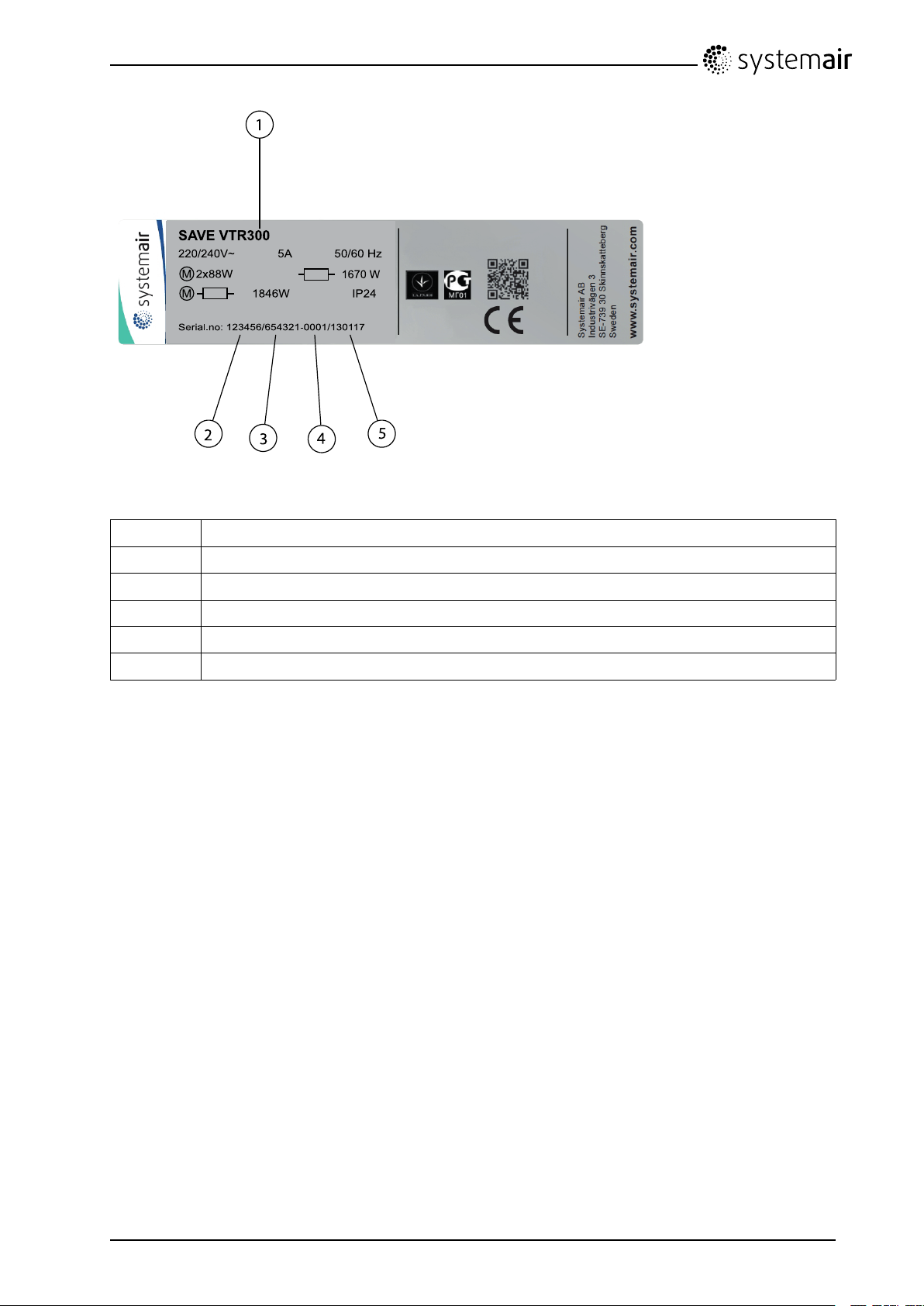
9.6Typelabel
Beforecallingyourservicerepresentative,makeanoteofthespecicationandproductionnumberfrom
thetypelabel,whichcanbefoundonthesideoftheunits,nexttotheexternalconnections.
SAVEVTR300/BInstallationandService
208348
39
SystemairAB
Page 42
S AVE VTR3 0 0
1670 W
220/240V~
5A 50 /60 Hz
IP2 418 46 W
2x8 8WM
M
Se rial.no : 12 34 56 /654 321-0 00 1/1 30 117
1
2
3
4
5
Fig.14Typelabel
PositionDescription
1
Productcode(productspecication)
2Productitemnumber
3Productionordernumber
4
5
Consecutivenumber
Productiondate(YY .MM.DD)
SAVEVTR300/BInstallationandService
208348
40
SystemairAB
Page 43

SAVEVTR300/BInstallationandService
208348
41
SystemairAB
Page 44

lastpage
SystemairABreservestherighttomakechangesandimprovementstothecontents
ofthismanualwithoutpriornotice.
SystemairAB
Industrivägen3
SE-73930Skinnskatteberg,Sweden
Phone+4622244000
Fax+4622244099
www.systemair.com
208348
 Loading...